WO2014133068A1 - セラミック接合体および流路体 - Google Patents
セラミック接合体および流路体 Download PDFInfo
- Publication number
- WO2014133068A1 WO2014133068A1 PCT/JP2014/054838 JP2014054838W WO2014133068A1 WO 2014133068 A1 WO2014133068 A1 WO 2014133068A1 JP 2014054838 W JP2014054838 W JP 2014054838W WO 2014133068 A1 WO2014133068 A1 WO 2014133068A1
- Authority
- WO
- WIPO (PCT)
- Prior art keywords
- silicon carbide
- sintered body
- silicon
- layer
- carbide sintered
- Prior art date
- Legal status (The legal status is an assumption and is not a legal conclusion. Google has not performed a legal analysis and makes no representation as to the accuracy of the status listed.)
- Ceased
Links
Images


Classifications
-
- B—PERFORMING OPERATIONS; TRANSPORTING
- B32—LAYERED PRODUCTS
- B32B—LAYERED PRODUCTS, i.e. PRODUCTS BUILT-UP OF STRATA OF FLAT OR NON-FLAT, e.g. CELLULAR OR HONEYCOMB, FORM
- B32B18/00—Layered products essentially comprising ceramics, e.g. refractory products
-
- C—CHEMISTRY; METALLURGY
- C04—CEMENTS; CONCRETE; ARTIFICIAL STONE; CERAMICS; REFRACTORIES
- C04B—LIME, MAGNESIA; SLAG; CEMENTS; COMPOSITIONS THEREOF, e.g. MORTARS, CONCRETE OR LIKE BUILDING MATERIALS; ARTIFICIAL STONE; CERAMICS; REFRACTORIES; TREATMENT OF NATURAL STONE
- C04B37/00—Joining burned ceramic articles with other burned ceramic articles or other articles by heating
- C04B37/003—Joining burned ceramic articles with other burned ceramic articles or other articles by heating by means of an interlayer consisting of a combination of materials selected from glass, or ceramic material with metals, metal oxides or metal salts
- C04B37/005—Joining burned ceramic articles with other burned ceramic articles or other articles by heating by means of an interlayer consisting of a combination of materials selected from glass, or ceramic material with metals, metal oxides or metal salts consisting of glass or ceramic material
-
- B—PERFORMING OPERATIONS; TRANSPORTING
- B32—LAYERED PRODUCTS
- B32B—LAYERED PRODUCTS, i.e. PRODUCTS BUILT-UP OF STRATA OF FLAT OR NON-FLAT, e.g. CELLULAR OR HONEYCOMB, FORM
- B32B1/00—Layered products having a non-planar shape
- B32B1/08—Tubular products
-
- B—PERFORMING OPERATIONS; TRANSPORTING
- B32—LAYERED PRODUCTS
- B32B—LAYERED PRODUCTS, i.e. PRODUCTS BUILT-UP OF STRATA OF FLAT OR NON-FLAT, e.g. CELLULAR OR HONEYCOMB, FORM
- B32B7/00—Layered products characterised by the relation between layers; Layered products characterised by the relative orientation of features between layers, or by the relative values of a measurable parameter between layers, i.e. products comprising layers having different physical, chemical or physicochemical properties; Layered products characterised by the interconnection of layers
- B32B7/04—Interconnection of layers
- B32B7/12—Interconnection of layers using interposed adhesives or interposed materials with bonding properties
-
- C—CHEMISTRY; METALLURGY
- C04—CEMENTS; CONCRETE; ARTIFICIAL STONE; CERAMICS; REFRACTORIES
- C04B—LIME, MAGNESIA; SLAG; CEMENTS; COMPOSITIONS THEREOF, e.g. MORTARS, CONCRETE OR LIKE BUILDING MATERIALS; ARTIFICIAL STONE; CERAMICS; REFRACTORIES; TREATMENT OF NATURAL STONE
- C04B37/00—Joining burned ceramic articles with other burned ceramic articles or other articles by heating
- C04B37/003—Joining burned ceramic articles with other burned ceramic articles or other articles by heating by means of an interlayer consisting of a combination of materials selected from glass, or ceramic material with metals, metal oxides or metal salts
-
- B—PERFORMING OPERATIONS; TRANSPORTING
- B32—LAYERED PRODUCTS
- B32B—LAYERED PRODUCTS, i.e. PRODUCTS BUILT-UP OF STRATA OF FLAT OR NON-FLAT, e.g. CELLULAR OR HONEYCOMB, FORM
- B32B2250/00—Layers arrangement
- B32B2250/02—2 layers
-
- B—PERFORMING OPERATIONS; TRANSPORTING
- B32—LAYERED PRODUCTS
- B32B—LAYERED PRODUCTS, i.e. PRODUCTS BUILT-UP OF STRATA OF FLAT OR NON-FLAT, e.g. CELLULAR OR HONEYCOMB, FORM
- B32B2255/00—Coating on the layer surface
- B32B2255/20—Inorganic coating
- B32B2255/205—Metallic coating
-
- B—PERFORMING OPERATIONS; TRANSPORTING
- B32—LAYERED PRODUCTS
- B32B—LAYERED PRODUCTS, i.e. PRODUCTS BUILT-UP OF STRATA OF FLAT OR NON-FLAT, e.g. CELLULAR OR HONEYCOMB, FORM
- B32B2307/00—Properties of the layers or laminate
- B32B2307/30—Properties of the layers or laminate having particular thermal properties
- B32B2307/306—Resistant to heat
-
- B—PERFORMING OPERATIONS; TRANSPORTING
- B32—LAYERED PRODUCTS
- B32B—LAYERED PRODUCTS, i.e. PRODUCTS BUILT-UP OF STRATA OF FLAT OR NON-FLAT, e.g. CELLULAR OR HONEYCOMB, FORM
- B32B2597/00—Tubular articles, e.g. hoses, pipes
-
- C—CHEMISTRY; METALLURGY
- C04—CEMENTS; CONCRETE; ARTIFICIAL STONE; CERAMICS; REFRACTORIES
- C04B—LIME, MAGNESIA; SLAG; CEMENTS; COMPOSITIONS THEREOF, e.g. MORTARS, CONCRETE OR LIKE BUILDING MATERIALS; ARTIFICIAL STONE; CERAMICS; REFRACTORIES; TREATMENT OF NATURAL STONE
- C04B2237/00—Aspects relating to ceramic laminates or to joining of ceramic articles with other articles by heating
- C04B2237/02—Aspects relating to interlayers, e.g. used to join ceramic articles with other articles by heating
- C04B2237/04—Ceramic interlayers
- C04B2237/08—Non-oxidic interlayers
- C04B2237/083—Carbide interlayers, e.g. silicon carbide interlayers
-
- C—CHEMISTRY; METALLURGY
- C04—CEMENTS; CONCRETE; ARTIFICIAL STONE; CERAMICS; REFRACTORIES
- C04B—LIME, MAGNESIA; SLAG; CEMENTS; COMPOSITIONS THEREOF, e.g. MORTARS, CONCRETE OR LIKE BUILDING MATERIALS; ARTIFICIAL STONE; CERAMICS; REFRACTORIES; TREATMENT OF NATURAL STONE
- C04B2237/00—Aspects relating to ceramic laminates or to joining of ceramic articles with other articles by heating
- C04B2237/02—Aspects relating to interlayers, e.g. used to join ceramic articles with other articles by heating
- C04B2237/04—Ceramic interlayers
- C04B2237/09—Ceramic interlayers wherein the active component for bonding is not the largest fraction of the interlayer
- C04B2237/095—The active component for bonding being silicon
-
- C—CHEMISTRY; METALLURGY
- C04—CEMENTS; CONCRETE; ARTIFICIAL STONE; CERAMICS; REFRACTORIES
- C04B—LIME, MAGNESIA; SLAG; CEMENTS; COMPOSITIONS THEREOF, e.g. MORTARS, CONCRETE OR LIKE BUILDING MATERIALS; ARTIFICIAL STONE; CERAMICS; REFRACTORIES; TREATMENT OF NATURAL STONE
- C04B2237/00—Aspects relating to ceramic laminates or to joining of ceramic articles with other articles by heating
- C04B2237/02—Aspects relating to interlayers, e.g. used to join ceramic articles with other articles by heating
- C04B2237/16—Silicon interlayers
-
- C—CHEMISTRY; METALLURGY
- C04—CEMENTS; CONCRETE; ARTIFICIAL STONE; CERAMICS; REFRACTORIES
- C04B—LIME, MAGNESIA; SLAG; CEMENTS; COMPOSITIONS THEREOF, e.g. MORTARS, CONCRETE OR LIKE BUILDING MATERIALS; ARTIFICIAL STONE; CERAMICS; REFRACTORIES; TREATMENT OF NATURAL STONE
- C04B2237/00—Aspects relating to ceramic laminates or to joining of ceramic articles with other articles by heating
- C04B2237/30—Composition of layers of ceramic laminates or of ceramic or metallic articles to be joined by heating, e.g. Si substrates
- C04B2237/32—Ceramic
- C04B2237/36—Non-oxidic
- C04B2237/365—Silicon carbide
-
- C—CHEMISTRY; METALLURGY
- C04—CEMENTS; CONCRETE; ARTIFICIAL STONE; CERAMICS; REFRACTORIES
- C04B—LIME, MAGNESIA; SLAG; CEMENTS; COMPOSITIONS THEREOF, e.g. MORTARS, CONCRETE OR LIKE BUILDING MATERIALS; ARTIFICIAL STONE; CERAMICS; REFRACTORIES; TREATMENT OF NATURAL STONE
- C04B2237/00—Aspects relating to ceramic laminates or to joining of ceramic articles with other articles by heating
- C04B2237/50—Processing aspects relating to ceramic laminates or to the joining of ceramic articles with other articles by heating
- C04B2237/72—Forming laminates or joined articles comprising at least two interlayers directly next to each other
-
- C—CHEMISTRY; METALLURGY
- C04—CEMENTS; CONCRETE; ARTIFICIAL STONE; CERAMICS; REFRACTORIES
- C04B—LIME, MAGNESIA; SLAG; CEMENTS; COMPOSITIONS THEREOF, e.g. MORTARS, CONCRETE OR LIKE BUILDING MATERIALS; ARTIFICIAL STONE; CERAMICS; REFRACTORIES; TREATMENT OF NATURAL STONE
- C04B2237/00—Aspects relating to ceramic laminates or to joining of ceramic articles with other articles by heating
- C04B2237/50—Processing aspects relating to ceramic laminates or to the joining of ceramic articles with other articles by heating
- C04B2237/76—Forming laminates or joined articles comprising at least one member in the form other than a sheet or disc, e.g. two tubes or a tube and a sheet or disc
-
- C—CHEMISTRY; METALLURGY
- C04—CEMENTS; CONCRETE; ARTIFICIAL STONE; CERAMICS; REFRACTORIES
- C04B—LIME, MAGNESIA; SLAG; CEMENTS; COMPOSITIONS THEREOF, e.g. MORTARS, CONCRETE OR LIKE BUILDING MATERIALS; ARTIFICIAL STONE; CERAMICS; REFRACTORIES; TREATMENT OF NATURAL STONE
- C04B2237/00—Aspects relating to ceramic laminates or to joining of ceramic articles with other articles by heating
- C04B2237/50—Processing aspects relating to ceramic laminates or to the joining of ceramic articles with other articles by heating
- C04B2237/76—Forming laminates or joined articles comprising at least one member in the form other than a sheet or disc, e.g. two tubes or a tube and a sheet or disc
- C04B2237/765—Forming laminates or joined articles comprising at least one member in the form other than a sheet or disc, e.g. two tubes or a tube and a sheet or disc at least one member being a tube
Definitions
- the present invention relates to a ceramic joined body in which silicon carbide sintered bodies are joined together and a flow path body in which a flow path is provided in the ceramic joined body.
- Silicon carbide-based sintered bodies are used in a wide range of fields because of their high mechanical strength and excellent properties such as heat resistance and corrosion resistance.
- a bonded body for example, in Patent Document 1, in a bonded body in which two or more silicon carbide ceramic members are bonded using silicon, at a corner of a plane which is a bonded portion of at least one silicon carbide ceramic member.
- a silicon carbide ceramic joined body that has been subjected to C-plane machining has been proposed.
- a flow passage body made of such a ceramic joined body is also required to have excellent airtightness.
- the present invention has been devised to satisfy the above-described requirements, and an object thereof is to provide a ceramic joined body having high joint strength and a flow path body in which a flow path is provided in the ceramic joined body. It is.
- the ceramic joined body of the present invention is a ceramic joined body in which a first silicon carbide sintered body and a second silicon carbide sintered body are joined by a joining layer, and the joining layer is made of metal silicon. It is covered with a first covering layer as a main component, and the first covering layer is provided over the first silicon carbide sintered body and the second silicon carbide sintered body. It is characterized by.
- the channel body of the present invention is characterized in that a channel is provided in the ceramic joined body having the above configuration.
- the ceramic joined body of the present invention has a high joining strength.
- the flow path body of the present invention has high bonding strength.
- the joint when used as a flow path, it has even better airtightness, so even when the temperature of the fluid or the environment of use is high or a harmful fluid is used. There is little leakage from the part and it can be used for a long time.
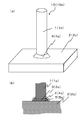
- FIG. 1 An example of the ceramic joined body of this embodiment is shown, (a) is a perspective view, (b) is a partial cross-sectional view at a joined portion.
- the other example of the ceramic joined body of this embodiment is shown, (a) is a perspective view, (b) is a fragmentary sectional view in a joined part.
- Still another example of the ceramic joined body of the present embodiment is shown, (a) is a perspective view, and (b) is a partial cross-sectional view at a joined portion.
- Still another example of the ceramic joined body of the present embodiment is shown, (a) is a perspective view, and (b) is a partial cross-sectional view at a joined portion.
- FIG. 1 and 2 show an example of a ceramic joined body of the present embodiment, (a) is a perspective view, and (b) is a partial cross-sectional view at a joined portion.
- numerals and alphabets are used for identification, but in the following description, only the numerals are described except for the description of only the ceramic joined body shown in FIG. 1 or FIG.
- FIG. 2 shows a ceramic joined body 10 in which a first silicon carbide sintered body 1 and a second silicon carbide sintered body 2 are joined by a joining layer 3.
- the first silicon carbide sintered body 1a has a cylindrical shape
- the second silicon carbide sintered body 2a has a flat plate shape. Is shown.
- each of the first silicon carbide sintered body 1b and the second silicon carbide sintered body 2b has a cylindrical shape.
- the shapes of the first silicon carbide sintered body 1 and the second silicon carbide sintered body 2 are not limited.
- the joining layer 3 is covered with the first covering layer 4 mainly composed of metallic silicon, and the first covering layer 4 is composed of the first silicon carbide. It is provided over the sintered body and the second silicon carbide sintered body.
- the ceramic bonded body 10 of the present embodiment has the first silicon carbide-based sintered body 1 and the second silicon carbide-based sintered body 2 bonded firmly, and is high.
- a ceramic bonded body having bonding strength is obtained.
- the high bonding strength is obtained because the metal silicon that is the main component of the first coating layer 4 is wetted by the first silicon carbide sintered body 1 and the second silicon carbide sintered body 2. It is also attributed to the good nature.
- the silicon carbide sintered body in the present embodiment is one in which silicon carbide occupies 70% by mass or more out of 100% by mass of all components constituting the silicon carbide based sintered body.
- the main component in the 1st coating layer 4 is a component which occupies 80 mass% or more among 100 mass% of all the components which comprise the 1st coating layer 4, It is preferable that it is 90 mass% or more. More preferably, it is 95% by mass or more.
- the bonding layer 3 between the first silicon carbide sintered body 1 and the second silicon carbide sintered body 2 is covered with a first coating layer 4 mainly composed of metallic silicon, Whether one coating layer 4 extends over the first silicon carbide sintered body 1 and the second silicon carbide sintered body 2 may be confirmed as follows.
- the ceramic bonded body 10 is cut so that the first silicon carbide sintered body 1, the second silicon carbide sintered body 2 and the bonding layer 3 can be confirmed, and the cut surface is polished with diamond abrasive grains or the like. It is processed into a mirror surface (hereinafter simply referred to as a mirror surface) using an agent, and this mirror surface is observed with a scanning electron microscope (SEM), and the bonding layer 3 is formed with an energy dispersive analyzer (EDS) attached to the SEM. What is necessary is just to confirm presence of metal silicon (Si) by irradiating X-ray
- SEM scanning electron microscope
- first silicon carbide sintered body 1 and the second silicon carbide sintered body 2 and the bonding layer 3 are distinguished from each other by a magnification (for example, a bonding interface can be determined using a reflected electron image of SEM). , 150 times or more and 1000 times or less) may be selected as appropriate, and the mirror surface may be observed and discriminated by the bonding interface.
- a magnification for example, a bonding interface can be determined using a reflected electron image of SEM.
- a bonding interface can be determined using a reflected electron image of SEM.
- 150 times or more and 1000 times or less may be selected as appropriate, and the mirror surface may be observed and discriminated by the bonding interface.
- EPMA electron beam microanalyzer
- surface analysis of each element on the mirror surface is performed, and the first silicon carbide sintered body 1, the second silicon carbide sintered body 2, and the bonding layer 3 are obtained. You may discriminate
- the components constituting the joined body first, using an X-ray diffractometer (XRD), identification of the compound using the JCPDS card from the value of 2 ⁇ obtained (2 ⁇ is the diffraction angle) is performed. To do. Further, for example, quantitative analysis of the metal element is performed using an ICP (Inductively-Coupled-Plasma) emission spectrometer (ICP). Then, if the compound measured and measured by XRD is silicon carbide, measured by ICP and the content of silicon (Si) converted to silicon carbide (SiC) is 70% by mass or more, silicon carbide A sintered material. Moreover, content can be calculated
- ICP Inductively-Coupled-Plasma emission spectrometer
- the bonding layer 3 is mainly composed of silicon carbide.
- the main component of bonding layer 3 is made of silicon carbide, the linear expansion coefficient approximates that of each of first silicon carbide sintered body 1 and second silicon carbide sintered body 2. Even if repeatedly exposed, cracks are less likely to occur inside the bonding layer 3.
- the main component in the bonding layer 3 is a component exceeding 50% by mass out of 100% by mass of all the components constituting the bonding layer 3.
- metal silicon is contained in addition to the silicon carbide that is the main component in the bonding layer 3. If metal silicon is included in addition to silicon carbide, metal silicon exists around silicon carbide that serves as an aggregate to connect silicon carbide together, and voids around silicon carbide are reduced. Has strength.
- the presence or absence of silicon carbide in the bonding layer 3 may be identified using a JCPDS card based on the obtained 2 ⁇ (2 ⁇ is the diffraction angle) using XRD. Or what is necessary is just to confirm using SEM and attached EDS. Specifically, the mirror surface may be observed with an SEM, and Si and C may be confirmed by irradiating X-rays on crystal particles confirmed in the observation region with an EDS attached to the SEM. In addition, about metallic silicon, it can confirm if X-rays are irradiated to parts other than a crystal grain.
- the carbon content may be measured with an infrared absorber and the carbon (c) content may be converted to silicon carbide (SiC). If the silicon carbide content obtained here exceeds 50%, silicon carbide is the main component of bonding layer 3.
- the bonding layer 3 preferably contains metal silicon and at least one metal component of copper and manganese.
- Metallic silicon can connect silicon carbide in the bonding layer 3 to increase the bonding strength.
- the metal component described above is included together with metal silicon, these metal components have a lower melting point than metal silicon and solidify later than metal silicon. Even if a crack occurs, the metal component fills the crack, so that the bonding strength is maintained and the durability is excellent.
- the total content of copper and manganese is preferably 1% by mass or more and 40% by mass or less out of 100% by mass of all the components constituting the bonding layer 3.
- the total content of copper and manganese is 1% by mass or more and 40% by mass or less, the eutectic point of metallic silicon and copper or manganese can be increased, so that the bonding strength of the bonding layer 3 in a high temperature environment is increased. can do.
- the contents of copper and manganese in the bonding layer 3 can be confirmed by using ICP, EDS, or EPMA.
- the dispersion degree of the silicon carbide particles in the bonding layer 3 is 0.3 or more and 0.9 or less.
- the dispersity is not less than 0.3 and not more than 0.9, since the silicon carbide crystal particles are dispersed and exist in the bonding layer 3, even if the silicon silicon is repeatedly exposed to a high temperature and cracks are generated in the metal silicon. The progress is blocked by the silicon carbide crystal particles. Therefore, it has a high bonding strength even in a high temperature environment.
- the degree of dispersion is a value obtained by dividing the standard deviation of the distance between the centers of gravity by the average value of the distance between the centers of gravity, and an image obtained by observing the cross section of the bonding layer 3 is image analysis software “A image-kun”.
- the cross section of the bonding layer 3 refers to the ceramic bonded body 10 cut, and diamond abrasive grains having an average particle size of 0.1 ⁇ m are polished to a polishing cloth (for example, a polishing cloth (code No. 410 or No. 9450)) is a mirror surface obtained by polishing the bonding layer 3 after dropping.
- an image is a portion where silicon carbide particles are observed on average from the cross section of the bonding layer 3, and an area of 1.1 ⁇ 10 4 ⁇ m 2 (for example, horizontal) using a SEM at a magnification of 1000 times.
- This is an image in a range in which the length in the direction is 128 ⁇ m and the length in the vertical direction is 86 ⁇ m.
- the setting conditions at the time of analysis the brightness of the particles is dark, the binarization method is automatic, and the small figure removal area is 0 ⁇ m.
- FIGS. 3 and 4 show the ceramic joined body of the present embodiment, (a) is a perspective view, and (b) is a partial cross-sectional view at each joined portion.
- the ceramic joined bodies 10c and 10d of the embodiment shown in FIGS. 3 and 4 are different from the ceramic joined bodies 10a and 10b of the embodiment shown in FIGS. 4 is provided with a second coating layer 5 mainly composed of silicon carbide.
- the ceramic joined body 10d of the present embodiment shown in FIG. 4 includes the first silicon carbide sintered body 1b and the second silicon carbide based on the ceramic joined body 10b of the present embodiment shown in FIG.
- Each shape of the sintered body 2b is cylindrical, whereas it is cylindrical.
- the ceramic joined body 10d shown in FIG. 4 when it is a structure like the ceramic joined body 10d shown in FIG. 4, it can be used as a flow path body by making the inside of the cylindrical shape a flow path through which a fluid flows. Due to the bonding strength and excellent airtightness, it is possible to flow a high-temperature fluid or a harmful fluid.
- the main component in the second coating layer 5 is a component exceeding 50% by mass out of 100% by mass of all the components constituting the second coating layer 5.
- metal silicon is contained.
- the presence / absence of silicon carbide in the second coating layer 5 and the calculation method of the content may be performed by the same method as in the case of the bonding layer 3 described above.
- the silicon source is silicon carbide and metal silicon
- the content of metal silicon is measured by ICP, and is necessary for calculating the silicon carbide content. What is necessary is just to make content of metal silicon other than the silicon which did.
- pores are not present in the joining layer 3.
- the presence or absence of pores in bonding layer 3 may be determined from the backscattered electron image in the same manner as when first silicon carbide sintered body 1, second silicon carbide sintered body 2 and bonding layer 3 are discriminated.
- the pore does not exist when the area occupation rate of the pore calculated using image analysis software or the like is less than 0.2%.
- first silicon carbide sintered body 1 and the second silicon carbide sintered body 2 constituting the ceramic joined body 10 of the present embodiment have a relative density of 95 volume% or more and 99 volume% or less. Preferably it is.
- the apparent density of the silicon carbide sintered body is obtained according to JIS R 1634-1998.
- the apparent density may be obtained by dividing by the theoretical density of the silicon carbide sintered body.
- the first silicon carbide sintered body 1 and the second silicon carbide sintered body 2 may be combined with different relative densities depending on the environment used. For example, use a sintered body with a high relative density when you want to efficiently transfer heat received from the outside to the fluid, or use a sintered body with a low relative density when you do not want to dissipate the heat of the fluid. can do.
- the surface of the first coating layer 4 constituting the ceramic joined body 10 of the present embodiment has a metallic luster.
- the surface reflectance in the visible light region is preferably 55% or more.
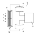
- FIG. 5 is a schematic view of a concentrating solar power generation device showing an example of the use of the flow path body of the present embodiment.
- a concentrating solar power generation apparatus 20 shown in FIG. 5 heats a medium with the heat of condensed sunlight and generates power using the heat of the heated medium.
- the heater 12, the hot medium storage tank 13, and the energy conversion system 14 are configured.
- the flow up to the power generation is that the medium is pumped from the low temperature medium storage tank 11 to the heat collector 12 and the collected sunlight is applied to the heat collector 12 to heat the medium.
- Electric power is generated by the energy conversion system 14 using the thermal energy of the heated medium stored in the storage tank 13 and pumped from the hot medium storage tank 13.
- the medium deprived of heat is sent to the low-temperature medium storage tank 11, and by repeating this cycle, electricity can be obtained without using fuel resources and without emitting greenhouse gases. It is useful in terms of environmental and environmental aspects.
- the heat collector 12 incorporates a plurality of flow path bodies 15 provided with a flow path for the medium.
- the flow path bodies 15 are long members extending several meters, The channel body 15 that receives heat by light must be able to withstand high temperatures.
- the flow path body 15 has the same configuration as the ceramic joined body 10d shown in FIG. 4, and since the flow path body 15 is made of the ceramic joined body 10d of the present embodiment, high bonding strength and excellent performance can be obtained. Therefore, it is possible to provide a highly reliable concentrating solar power generation device 20 that can stably generate power over a long period of time.
- the flow path body 15 of this embodiment is not restricted to the case of the above-mentioned shape,
- the cylindrical 1st silicon carbide sintered body 1 and the 2nd plate-shaped 2nd which has a flow path inside.
- the silicon carbide sintered body 2 may be joined, and a cylindrical interior and a flat interior may be used as a flow path.
- the cylindrical first silicon carbide sintered body 1 and the flat plate-like second silicon carbide sintered body 2 having a flow path inside are joined to each other so that only the flat plate-shaped inside has a flow path.
- the columnar first silicon carbide sintered body 1 may support the plate-like second silicon carbide sintered body 2.
- the flow path body 15 can have various shapes depending on the combination of the objects to be joined, and the cylindrical first silicon carbide sintered body 1 and the flat plate-shaped first body having the flow path therein. If the two silicon carbide sintered bodies 2 are joined and laminated, the flow path body 15 of the present embodiment can also be applied to a heat exchanger.
- a first silicon carbide sintered body 1 and a second silicon carbide sintered body 2 are prepared.
- a paste for example, silicon carbide powder in an organic solvent
- Metal silicon powder, carbon powder, ethyl cellulose, or an acrylic binder is applied, and then the joint surfaces are aligned and pressed from the direction perpendicular to the joint surface.
- the mass of silicon carbide powder may be 50 mass% or more out of the total mass of silicon carbide powder, metal silicon powder, and carbon powder of 100 mass%.
- the pressurization when joining in flat form may be based on the dead weight of the member joined to a flat member.
- the paste to be the joining layer 3 may contain at least one of copper powder and manganese powder.
- a stirring defoaming device is used.
- a solvent, silicon carbide powder, ethyl cellulose or acrylic binder, and carbon powder are added, and the container is rotated at 2000 rpm for 2 to 12 minutes, and then rotated at 2200 rpm for 30 seconds. .
- the first coating layer is formed so as to cover the first paste of the silicon carbide-based sintered body 1 and the second silicon carbide-based sintered body 2 so as to cover the paste that becomes the applied bonding layer 3.
- 4 paste for example, containing metal silicon powder, ethyl cellulose or acrylic binder in an organic solvent
- drying at a temperature of 80 ° C. to 200 ° C. and a holding time of 8 hours to 14 hours. .
- the ceramic joined body 10 of the present embodiment is heat-treated in an inert gas atmosphere such as argon at a pressure of 1 atm, a holding temperature of 1400 ° C. to 1500 ° C., and a holding time of 30 minutes to 90 minutes.
- an inert gas atmosphere such as argon
- the rate of temperature increase from 1100 ° C. to the holding temperature is preferably 2 ° C./min to 2.5 ° C./min, for example.
- heat processing should just be performed in a vacuum atmosphere.
- the paste (the second coating layer 5 is formed on the outer periphery of the paste serving as the bonding layer 3.
- a paste to be the first coating layer 4 may be applied.
- mass of silicon carbide powder is more than 50 mass% out of mass total 100 mass% of silicon carbide powder, metal silicon powder, and carbon powder. do it.
- the paste that becomes the bonding layer 3 and the paste that becomes the second coating layer 5 are made of the same component, for example, if the ceramic bonded body 10c shown in FIG.
- the bonding layer 3 may extend up to the extended line of the outer peripheral surface of the sintered body 1, and the others may be regarded as the second coating layer 5.
- the temperature was raised to a holding temperature in an inert gas atmosphere such as argon at a pressure lower than 1 atm and reached the holding temperature.
- Heat treatment may be performed at a pressure of 1 atm, a holding temperature of 1400 ° C. to 1500 ° C., a holding time of 30 minutes to 90 minutes.
- a paste that becomes the joining layer 3 containing silicon carbide powder, carbon powder, ethyl cellulose, or an acrylic binder in an organic solvent is used and melted by heat treatment.
- the metal silicon in the paste that becomes the first covering layer 4 may be allowed to flow.
- the bonding layer 3 contains at least one of copper and manganese together with metal silicon melted by heat treatment. Can be allowed to flow into.
- a first silicon carbide sintered body and a second silicon carbide sintered body each having a prismatic shape were prepared.
- the ceramic joined body produced in Example 1 has a test piece size conforming to JIS R 1624-2010, and the joining layer is located at the center in the longitudinal direction.
- the paste that becomes the bonding layer so that the thickness of the bonding layer becomes 40 ⁇ m in terpineol, which is an organic solvent, silicon carbide powder, metal silicon powder
- a second silicon carbide sintered body was placed thereon.
- sample No. for sample No. 1 the mass ratio is silicon carbide powder 45, metal silicon powder 54, carbon powder 1, and sample no. For 2 to 5, the mass ratio was set to silicon carbide powder 54, metal silicon powder 45, and carbon powder 1. Further, terpineol was 30 parts by mass, ethylcellulose was 12 parts by mass with respect to a total of 100 parts by mass of the powder, and the same was applied to the paste as the first coating layer and the paste as the second coating layer. Furthermore, the pressurization in the vertical direction to the joint surface was caused by the weight of the second silicon carbide sintered body.
- the first coating layer containing metal silicon as a main component covers the surface of the paste serving as the bonding layer, and covers the first silicon carbide sintered body and the second silicon carbide sintered body.
- the paste it contains silicon powder and ethyl cellulose in the organic solvent used as the first coating layer was applied.
- Sample No. For 3 and 4 after applying a paste to be a second coating layer (including silicon carbide powder, carbon powder and ethyl cellulose in an organic solvent) and covering the paste to be a bonding layer, the second coating layer
- the paste to be the first coating layer was applied so as to cover the surface of the paste to be.
- Sample No. for sample No. 3 the mass ratio is silicon carbide powder 45, metal silicon powder 54, carbon powder 1, and sample no.
- the mass ratio was silicon carbide powder 54, metal silicon powder 45, and carbon powder 1.
- first silicon carbide sintered body and the second silicon carbide sintered body are joined together by heat treatment in an argon atmosphere at a pressure of 1 atm, a holding temperature of 1430 ° C., and a holding time of 60 minutes.
- Sample No. 1 to 5 ceramic joined bodies were obtained. Note that the rate of temperature increase from 1100 ° C. to the holding temperature was 2.2 ° C./min.
- sample No. In 1-4 the first silicon carbide sintered body and the second silicon carbide sintered body are bonded together by a bonding layer, and the bonding layer is covered with a first coating layer containing metal silicon as a main component. Since the first coating layer is provided over the first silicon carbide sintered body and the second silicon carbide sintered body, the sample no. It had a bonding strength higher than 5.
- sample no. Comparing 1 and 2 it was found that the main component of the bonding layer is preferably silicon carbide.
- Sample No. Comparing 1 to 4 it is preferable that the second coating layer is provided inside the first coating layer, and that the main component of the second coating layer is silicon carbide. I understood it.
- a sample size according to JIS R 1624-2010, a sample in which the bonding layer is located at the center in the longitudinal direction, and a sample according to JIS Z 2331-2006 were prepared.
- a paste made of 30 parts by mass of terpineol and 12 parts by mass of ethylcellulose with respect to 100 parts by mass of silicon carbide powder and silicon carbide powder was prepared as a paste to be a bonding layer.
- the mass ratio is the metal silicon powder 90, and the powder 10 of the components shown in Table 2, and terpineol is 30 parts by mass with respect to 100 parts by mass in total of the powder.
- a paste was prepared in which ethylcellulose was a bonding layer of 12 parts by mass. Sample No. For No. 6, the paste used as the first coating layer containing no metal component used in Example 1 was used.
- the surface of the paste serving as the bonding layer is covered with the first coating layer containing metal silicon as a main component, and over the first silicon carbide sintered body and the second silicon carbide sintered body, A paste to be the first coating layer was applied.
- each sample was produced by the method similar to Example 1 except apply
- the metal component such as copper or manganese is not included in the paste as the bonding layer, the sample No. As for 7 to 9, a metal component flows together with the metal silicon melted during the heat treatment, and the metal component is contained in the bonding layer.
- Each sample was placed in a heat treatment apparatus, and then heated up, held at 1250 ° C. for 10 hours in an atmosphere having an oxygen partial pressure of 10 ⁇ 9 MPa and containing water vapor, and then cooled to room temperature. Then, a cycle test was performed in which the temperature raising, holding, and temperature lowering processes were set as one cycle, and this process was repeated for 50 cycles.
- the leak amount of helium gas in the bonding layer was measured at room temperature in accordance with the vacuum spraying method (spray method) prescribed in JIS Z 2331-2006 for the sample subjected to the cycle test.
- "1" for the leak amount of 10 -10 Pa ⁇ m 3 / sec 10 -9 Pa ⁇ m 3 / sec of the sample the sample leakage amount is less than 10 -10 Pa ⁇ m 3 / sec " 2 ”was entered in Table 2.
- Example 2 the paste used as the first coating layer used in Example 2 was prepared. And each sample was produced by the same method as Example 2.
- Example 2 a cycle test was performed in the same manner as in Example 2, and the four-point bending strength at normal temperature of the sample before the cycle test and the sample after the cycle test was measured in accordance with JIS R 1624-2010.
- the values are shown in Table 3 as bonding strengths ⁇ 0 and ⁇ 1 , respectively. Further, the reduction rate ⁇ of the bonding strength was calculated and shown in Table 3.
- the leak amount of helium gas in the bonding layer was measured at room temperature in accordance with the vacuum spraying method (spray method) prescribed in JIS Z 2331-2006 for the sample subjected to the cycle test.
- "1" for the leak amount of 10 -10 Pa ⁇ m 3 / sec 10 -9 Pa ⁇ m 3 / sec of the sample the sample leakage amount is less than 10 -10 Pa ⁇ m 3 / sec " 2 ”was entered in Table 2.
- the dispersity of the silicon carbide particles in the bonding layer was determined by a method called the center-of-gravity distance method. Indicated.
- the brightness of the particle was dark, the binarization method was automatically performed, and the small figure removal area was 0 ⁇ m.
- sample No. Nos. 11 to 13 have excellent durability because the dispersion rate of silicon carbide particles in the bonding layer is 0.3 or more and 0.9 or less, and the rate of decrease in bonding strength is low and the amount of leakage is small even when a cycle test is performed. It was found that
- the ceramic joined body of the present embodiment has a high joining strength, so that it is possible to suitably increase the size, length and complexity of the member. Also, if a ceramic joined body is formed so as to have a flow path, it has excellent airtightness with high joint strength, so it can flow high-temperature fluids or harmful fluids. It was found that it is suitable for a member to be used.
- first silicon carbide sintered body 2 second silicon carbide sintered body 3: bonding layer 4: first coating layer 5: second coating layer 10: ceramic bonding body 15: flow path body 20: Concentrating solar power generator
Landscapes
- Chemical & Material Sciences (AREA)
- Engineering & Computer Science (AREA)
- Ceramic Engineering (AREA)
- Materials Engineering (AREA)
- Structural Engineering (AREA)
- Organic Chemistry (AREA)
- Mechanical Engineering (AREA)
- Ceramic Products (AREA)
Abstract
Description


2:第2の炭化珪素質焼結体
3:接合層
4:第1の被覆層
5:第2の被覆層
10:セラミック接合体
15:流路体
20:集光型太陽光発電装置
Claims (7)
- 第1の炭化珪素質焼結体と第2の炭化珪素質焼結体とが接合層で接合されたセラミック接合体であって、前記接合層は、金属珪素を主成分とする第1の被覆層により覆われており、該第1の被覆層は、前記第1の炭化珪素質焼結体および前記第2の炭化珪素質焼結体にわたって設けられていることを特徴とするセラミック接合体。
- 前記接合層は、主成分が炭化珪素であることを特徴とする請求項1に記載のセラミック接合体。
- 前記接合層は、金属珪素と、銅およびマンガンの少なくともいずれかとを含んでいることを特徴とする請求項2に記載のセラミック接合体。
- 前記接合層における前記炭化珪素の粒子の分散度が0.3以上0.9以下であることを特徴とする請求項2または請求項3に記載のセラミック接合体。
- 前記第1の被覆層の内側に、炭化珪素を主成分とする第2の被覆層を備えていることを特徴とする請求項1乃至請求項4のいずれかに記載のセラミック接合体。
- 前記接合層に、気孔が存在していないことを特徴とする請求項1乃至請求項5のいずれかに記載のセラミック接合体。
- 請求項1乃至請求項6のいずれかに記載のセラミック接合体に流路が設けられてなることを特徴とする流路体。
Priority Applications (3)
| Application Number | Priority Date | Filing Date | Title |
|---|---|---|---|
| EP14757217.6A EP2963002A4 (en) | 2013-02-27 | 2014-02-27 | CERAMICLY CONNECTED BODY AND CHANNEL BODY |
| JP2015503013A JP6001761B2 (ja) | 2013-02-27 | 2014-02-27 | セラミック接合体および流路体 |
| US14/771,190 US20160001526A1 (en) | 2013-02-27 | 2014-02-27 | Ceramic joined body and flow passage body |
Applications Claiming Priority (2)
| Application Number | Priority Date | Filing Date | Title |
|---|---|---|---|
| JP2013-037398 | 2013-02-27 | ||
| JP2013037398 | 2013-02-27 |
Publications (1)
| Publication Number | Publication Date |
|---|---|
| WO2014133068A1 true WO2014133068A1 (ja) | 2014-09-04 |
Family
ID=51428327
Family Applications (1)
| Application Number | Title | Priority Date | Filing Date |
|---|---|---|---|
| PCT/JP2014/054838 Ceased WO2014133068A1 (ja) | 2013-02-27 | 2014-02-27 | セラミック接合体および流路体 |
Country Status (4)
| Country | Link |
|---|---|
| US (1) | US20160001526A1 (ja) |
| EP (1) | EP2963002A4 (ja) |
| JP (1) | JP6001761B2 (ja) |
| WO (1) | WO2014133068A1 (ja) |
Cited By (7)
| Publication number | Priority date | Publication date | Assignee | Title |
|---|---|---|---|---|
| JP5729517B1 (ja) * | 2014-03-28 | 2015-06-03 | Toto株式会社 | 反応焼結炭化珪素部材 |
| JP2016108170A (ja) * | 2014-12-03 | 2016-06-20 | 京セラ株式会社 | セラミック流路体およびこれを備える熱交換器 |
| JP2016155734A (ja) * | 2015-02-26 | 2016-09-01 | 京セラ株式会社 | セラミック接合体およびセラミック流路体ならびにこれを備える熱交換器 |
| WO2017057470A1 (ja) * | 2015-09-29 | 2017-04-06 | 京セラ株式会社 | セラミック接合体 |
| JPWO2017146222A1 (ja) * | 2016-02-26 | 2018-12-13 | 京セラ株式会社 | セラミック接合体 |
| US12036695B2 (en) * | 2016-07-15 | 2024-07-16 | University of Pittsburgh—of the Commonwealth System of Higher Education | Apparatus and method for joining of carbide ceramics |
| US20250074832A1 (en) * | 2023-08-29 | 2025-03-06 | Ii-Vi Delaware, Inc. | Dry preform bonding for internal channeled reaction bonded ceramics |
Families Citing this family (1)
| Publication number | Priority date | Publication date | Assignee | Title |
|---|---|---|---|---|
| EP3156385B9 (en) * | 2014-08-28 | 2022-04-13 | KYOCERA Corporation | Ceramic bonded body and heat exchanger provided with same |
Citations (7)
| Publication number | Priority date | Publication date | Assignee | Title |
|---|---|---|---|---|
| JPS59190277A (ja) * | 1983-04-08 | 1984-10-29 | 旭硝子株式会社 | セラミツク管の接合体と接合法 |
| JPS61117172A (ja) * | 1984-11-13 | 1986-06-04 | 日本特殊陶業株式会社 | セラミツクスの接合構造 |
| JPH0282738U (ja) * | 1988-12-15 | 1990-06-26 | ||
| JPH0333071A (ja) * | 1989-06-28 | 1991-02-13 | Daihen Corp | Si含有炭化ケイ素セラミックス同士の電気接合方法 |
| JP2001261459A (ja) | 2000-03-23 | 2001-09-26 | Toshiba Ceramics Co Ltd | 炭化ケイ素セラミックス接合体およびその製造方法 |
| JP2003505329A (ja) * | 1999-07-23 | 2003-02-12 | エム キューブド テクノロジーズ, インコーポレイテッド | 改善された炭化ケイ素複合体及びその製造方法 |
| JP2007246319A (ja) * | 2006-03-15 | 2007-09-27 | Taiheiyo Cement Corp | 中空構造を有するセラミックス接合体 |
Family Cites Families (8)
| Publication number | Priority date | Publication date | Assignee | Title |
|---|---|---|---|---|
| CA1313762C (en) * | 1985-11-19 | 1993-02-23 | Sumitomo Electric Industries, Ltd. | Hard sintered compact for a tool |
| JP3057932B2 (ja) * | 1992-10-01 | 2000-07-04 | 三菱マテリアル株式会社 | セラミックス焼結体の接合方法 |
| US5683028A (en) * | 1996-05-03 | 1997-11-04 | Cvd, Incorporated | Bonding of silicon carbide components |
| FR2806405B1 (fr) * | 2000-03-14 | 2002-10-11 | Commissariat Energie Atomique | Procede d'assemblage de pieces en materiaux a base de sic par brasage refractaire non reactif, composition de brasure, et joint et assemblage refractaires obtenus par ce procede |
| JP4261130B2 (ja) * | 2002-06-18 | 2009-04-30 | 株式会社東芝 | シリコン/炭化ケイ素複合材料 |
| US8002487B2 (en) * | 2006-08-29 | 2011-08-23 | Innovative Consumer Solutions, Llc | Spreadable food dispenser |
| JP5322382B2 (ja) * | 2006-11-30 | 2013-10-23 | 株式会社東芝 | セラミックス複合部材とその製造方法 |
| FR2935622B1 (fr) * | 2008-09-05 | 2017-02-03 | Commissariat Energie Atomique | Procede d'assemblage de pieces carbonees par brasage refractaire |
-
2014
- 2014-02-27 WO PCT/JP2014/054838 patent/WO2014133068A1/ja not_active Ceased
- 2014-02-27 JP JP2015503013A patent/JP6001761B2/ja active Active
- 2014-02-27 US US14/771,190 patent/US20160001526A1/en not_active Abandoned
- 2014-02-27 EP EP14757217.6A patent/EP2963002A4/en not_active Withdrawn
Patent Citations (7)
| Publication number | Priority date | Publication date | Assignee | Title |
|---|---|---|---|---|
| JPS59190277A (ja) * | 1983-04-08 | 1984-10-29 | 旭硝子株式会社 | セラミツク管の接合体と接合法 |
| JPS61117172A (ja) * | 1984-11-13 | 1986-06-04 | 日本特殊陶業株式会社 | セラミツクスの接合構造 |
| JPH0282738U (ja) * | 1988-12-15 | 1990-06-26 | ||
| JPH0333071A (ja) * | 1989-06-28 | 1991-02-13 | Daihen Corp | Si含有炭化ケイ素セラミックス同士の電気接合方法 |
| JP2003505329A (ja) * | 1999-07-23 | 2003-02-12 | エム キューブド テクノロジーズ, インコーポレイテッド | 改善された炭化ケイ素複合体及びその製造方法 |
| JP2001261459A (ja) | 2000-03-23 | 2001-09-26 | Toshiba Ceramics Co Ltd | 炭化ケイ素セラミックス接合体およびその製造方法 |
| JP2007246319A (ja) * | 2006-03-15 | 2007-09-27 | Taiheiyo Cement Corp | 中空構造を有するセラミックス接合体 |
Non-Patent Citations (1)
| Title |
|---|
| See also references of EP2963002A4 |
Cited By (10)
| Publication number | Priority date | Publication date | Assignee | Title |
|---|---|---|---|---|
| JP5729517B1 (ja) * | 2014-03-28 | 2015-06-03 | Toto株式会社 | 反応焼結炭化珪素部材 |
| JP2016108170A (ja) * | 2014-12-03 | 2016-06-20 | 京セラ株式会社 | セラミック流路体およびこれを備える熱交換器 |
| JP2016155734A (ja) * | 2015-02-26 | 2016-09-01 | 京セラ株式会社 | セラミック接合体およびセラミック流路体ならびにこれを備える熱交換器 |
| WO2017057470A1 (ja) * | 2015-09-29 | 2017-04-06 | 京セラ株式会社 | セラミック接合体 |
| CN108025986A (zh) * | 2015-09-29 | 2018-05-11 | 京瓷株式会社 | 陶瓷接合体 |
| JPWO2017057470A1 (ja) * | 2015-09-29 | 2018-06-28 | 京セラ株式会社 | セラミック接合体 |
| US10689300B2 (en) | 2015-09-29 | 2020-06-23 | Kyocera Corporation | Ceramic bonded body |
| JPWO2017146222A1 (ja) * | 2016-02-26 | 2018-12-13 | 京セラ株式会社 | セラミック接合体 |
| US12036695B2 (en) * | 2016-07-15 | 2024-07-16 | University of Pittsburgh—of the Commonwealth System of Higher Education | Apparatus and method for joining of carbide ceramics |
| US20250074832A1 (en) * | 2023-08-29 | 2025-03-06 | Ii-Vi Delaware, Inc. | Dry preform bonding for internal channeled reaction bonded ceramics |
Also Published As
| Publication number | Publication date |
|---|---|
| US20160001526A1 (en) | 2016-01-07 |
| JPWO2014133068A1 (ja) | 2017-02-02 |
| EP2963002A1 (en) | 2016-01-06 |
| EP2963002A4 (en) | 2016-10-26 |
| JP6001761B2 (ja) | 2016-10-05 |
Similar Documents
| Publication | Publication Date | Title |
|---|---|---|
| JP6001761B2 (ja) | セラミック接合体および流路体 | |
| US10406640B2 (en) | Method for repairing ceramic matrix composite (CMC) articles | |
| US6692597B2 (en) | Ceramic joining | |
| CN105218156B (zh) | C/C复合材料表面ZrC‑SiC涂层制备方法 | |
| JP2014094855A (ja) | 炭化ケイ素セラミックス接合体及び炭化ケイ素セラミックス接合体の製造方法 | |
| CN103320633B (zh) | 一种低热膨胀系数铝基复合材料的制备方法 | |
| CN109881146A (zh) | 一种稀土元素y改性纯钨包埋渗铝抗氧化涂层的制备方法 | |
| CN104264148A (zh) | 一种钛合金表面真空钎涂金属陶瓷复合涂层的方法 | |
| JP5764506B2 (ja) | セラミックス多孔体−金属断熱材及びその製造方法 | |
| KR102098470B1 (ko) | 반도체 웨이퍼용 고온 금속 히터블럭 및 이의 제조 방법 | |
| KR102102625B1 (ko) | 세라믹 접합체 | |
| JP6306723B2 (ja) | セラミック接合体およびこれを備える熱交換器 | |
| JP2016069207A (ja) | セラミック流路体およびこれを備える熱交換器 | |
| JP2013216500A (ja) | 炭化珪素質接合体およびこれからなる伝熱管ならびにこの伝熱管を備える熱交換器 | |
| JP5322093B2 (ja) | プラズマ対向材およびその製造方法 | |
| JP6363485B2 (ja) | セラミック流路体およびこれを備える熱交換器 | |
| CN106282911A (zh) | 一种在金属钼表面制备高温抗氧化覆层的方法 | |
| JP6864470B2 (ja) | セラミック接合体 | |
| JP2015160776A (ja) | セラミック接合体および流路体 | |
| JP6556323B2 (ja) | セラミック接合体 | |
| Wasilewski et al. | Cu/LaCrO3 joining by local melt infiltration through laser cladding | |
| JP6208544B2 (ja) | セラミック接合体 | |
| JP6449680B2 (ja) | セラミック接合体およびセラミック流路体ならびにこれを備える熱交換器 | |
| WO2018021491A1 (ja) | セラミック接合体 | |
| KR100403790B1 (ko) | 마그네슘을 이용한 세라믹과 금속의 접합방법 |
Legal Events
| Date | Code | Title | Description |
|---|---|---|---|
| 121 | Ep: the epo has been informed by wipo that ep was designated in this application |
Ref document number: 14757217 Country of ref document: EP Kind code of ref document: A1 |
|
| ENP | Entry into the national phase |
Ref document number: 2015503013 Country of ref document: JP Kind code of ref document: A |
|
| NENP | Non-entry into the national phase |
Ref country code: DE |
|
| REEP | Request for entry into the european phase |
Ref document number: 2014757217 Country of ref document: EP |
|
| WWE | Wipo information: entry into national phase |
Ref document number: 14771190 Country of ref document: US Ref document number: 2014757217 Country of ref document: EP |