WO2014136304A1 - Matrice de coupe et procédé de coupe - Google Patents
Matrice de coupe et procédé de coupe Download PDFInfo
- Publication number
- WO2014136304A1 WO2014136304A1 PCT/JP2013/077703 JP2013077703W WO2014136304A1 WO 2014136304 A1 WO2014136304 A1 WO 2014136304A1 JP 2013077703 W JP2013077703 W JP 2013077703W WO 2014136304 A1 WO2014136304 A1 WO 2014136304A1
- Authority
- WO
- WIPO (PCT)
- Prior art keywords
- cutting
- groove
- processing
- cutting tip
- tip
- Prior art date
- Legal status (The legal status is an assumption and is not a legal conclusion. Google has not performed a legal analysis and makes no representation as to the accuracy of the status listed.)
- Ceased
Links
Images






Classifications
-
- B—PERFORMING OPERATIONS; TRANSPORTING
- B23—MACHINE TOOLS; METAL-WORKING NOT OTHERWISE PROVIDED FOR
- B23D—PLANING; SLOTTING; SHEARING; BROACHING; SAWING; FILING; SCRAPING; LIKE OPERATIONS FOR WORKING METAL BY REMOVING MATERIAL, NOT OTHERWISE PROVIDED FOR
- B23D11/00—Planing or slotting devices able to be attached to a machine tool, whether or not replacing an operative portion of the machine tool
-
- B—PERFORMING OPERATIONS; TRANSPORTING
- B21—MECHANICAL METAL-WORKING WITHOUT ESSENTIALLY REMOVING MATERIAL; PUNCHING METAL
- B21D—WORKING OR PROCESSING OF SHEET METAL OR METAL TUBES, RODS OR PROFILES WITHOUT ESSENTIALLY REMOVING MATERIAL; PUNCHING METAL
- B21D28/00—Shaping by press-cutting; Perforating
- B21D28/02—Punching blanks or articles with or without obtaining scrap; Notching
- B21D28/14—Dies
-
- B—PERFORMING OPERATIONS; TRANSPORTING
- B23—MACHINE TOOLS; METAL-WORKING NOT OTHERWISE PROVIDED FOR
- B23B—TURNING; BORING
- B23B27/00—Tools for turning or boring machines; Tools of a similar kind in general; Accessories therefor
- B23B27/14—Cutting tools of which the bits or tips or cutting inserts are of special material
- B23B27/16—Cutting tools of which the bits or tips or cutting inserts are of special material with exchangeable cutting bits or cutting inserts, e.g. able to be clamped
Definitions
- the present invention relates to a cutting die and a cutting method in which the life is extended by preventing wear of a cutting tip.
- a die apparatus is constituted by the punch P and the die D attached to the upper turret 6 and the lower turret 7 of the turret punch press (FIG. 8), and the cutting tip 33 is incorporated in the die D.
- the accuracy is further improved automatically without human intervention without increasing the number of steps and without limiting the size of the work. It is possible to achieve the action and effect that it is possible to deburr in a steady state.
- the cutting tip is originally used not only for deburring, but also for a wider range of cutting such as V grooving, film cutting, dross cutting, and chamfering.
- the cutting tip is not conventionally provided with a cooling means, and therefore, if used for a long time, it generates heat, the metal constituting the cutting tip is melted, and the cutting tip is abraded.
- An object of the present invention is to provide a cutting die and a cutting method in which the life is extended by preventing wear of a cutting tip.
- a cutting die D which has a cutting tip 50, is applied to a punch press, and cuts a work W in cooperation with the cutting punch P, A cooling mechanism 51 for cooling the cutting tip 50 is provided, and the cooling mechanism 51 is provided on the outer periphery of the die main body 41 and supplies the air A from the outside, and the cutting tip communicated with the circumferential groove 54 50, a cutting die D (FIGS.
- a cutting method (FIG. 14 (A)) characterized in that the chip center CC is aligned with the V-groove center VC to be obtained, and the cutting depths h1, h2, h3 are made deeper for each step.
- the cutting die D according to the present invention described in claim 1 (independent terms) (FIGS. 1 to 7), claims 7 to 9 (independent terms), and claims 11 to 14 (independent terms)
- the cutting method according to the present invention described (FIGS. 9 to 20) has the same or corresponding special technical features (Patent Act Article 37 (Patent Act Enforcement Regulations Article 25-8)). That is, the former is provided with the cooling mechanism 51 (FIG. 1, FIGS. 4 to 5), and the latter is caused by gradually cutting the cutting tip 50 into the workpiece W (FIGS. 9 and 14). By preventing the wear of the cutting tip, the life can be extended.
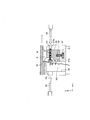
- FIG. 1 is an overall view of a die including a cutting die D according to the present invention and a cutting punch P cooperating therewith. It is a figure which shows the relationship between the die
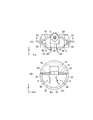
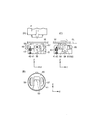
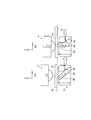
- FIG. It is a disassembled perspective view of FIG. It is a whole perspective view of die D for cuttings concerning the present invention. It is a figure which shows the cooling mechanism 51 and the discharge mechanism 52 which this invention comprises. It is a figure which shows embodiment in case this invention does not have an up-and-down movement apparatus. It is a figure which shows other embodiment in the case of FIG. It is a figure which shows the application example of this invention.
- FIG. 1 is an overall view of a die comprising a cutting die D according to the present invention and a cutting punch P cooperating therewith.
- the mold shown in FIG. 1 is applied to, for example, a turret punch press (FIG. 8), a ram striker 2 for the upper frame 1, a cutting punch P for the upper turret 6, and a lower turret 7 for the cutting. Dies for cutting D according to the present invention, which cooperate with the punches P, are respectively attached.
- a through hole 40 is formed in the upper turret 6 (FIG. 1), and the cutting punch P is supported on the upper edge of the through hole 40 via a lift spring 31.
- the cutting die D according to the present invention is fixed to the lower turret 7, and the cutting tip 50 is incorporated in the cutting die D.
- the cutting tip 50 is not only deburred, but also V-groove processing, film cutting, dross removal, chamfering, etc. by placing and moving the work W thereon. It is used for a wide range of cutting processes in general, and a cutting tool-like cutting edge 50A (FIG. 3), 50B, 50C, 50D is formed at the tip thereof.
- This cutting tip 50 (FIG. 2) is, for example, a single-sided type and has a clearance angle ⁇ , and is attached to a housing (tip holder) 36 via a bolt 37 which is a fixing means, which housing 36 is likewise It is attached to the die body 41 via a bolt 38 which is a fixing means.
- a recess 36A is formed in the housing 36 (FIG. 3), and the cutting tip 50 is fixed to the recess 36A via the bolt 37 passing therethrough.
- a discharge hole 39 is formed in the die main body 41 in the vicinity of the cutting tip 50 (FIG. 2), and the chips W1 generated when the workpiece W is cut through the cutting tip 50 are discharged to the outside It is supposed to be
- a tool 59 for handling the fixing means 37 for fixing the cutting tip 50 to the housing 36 for example, a hexagonal wrench for tightening or loosening the bolt 37 when the fixing means is the bolt 37, is A tool insertion hole 53 to be inserted is provided.
- the tool insertion hole 53 is provided only on the head portion 37A side and the shaft portion 37B side of the fixing means 37, or only on the head portion 37A side or only on the shaft portion 37B side.
- the bolt 38 (FIG. 2) is not loosened to take the housing 36 out of the die main body 41, and the bolt 37 is inserted through the tool insertion hole 53.
- the tip can be easily and quickly replaced by simply loosening and removing the old one from the recess 36A (FIG. 3) of the housing 36 and replacing it with a new one and tightening only the bolt 37 through the tool 59. it can.
- a circumferential groove 54 is provided on the outer periphery, and the circumferential groove 54 is cooled from an external device such as a power vacuum device. Air (oil mixed) A for air is supplied.
- an air hole 55 is provided which communicates with the circumferential groove 54 and allows the air A to be jetted toward the cutting tip 50.
- the air hole 55 starts from the circumferential groove 54, passes through the die body 41, and ends at a position facing the cutting tip 50.
- two air holes 55 are installed, for example, and air A is jetted from both sides of the cutting tip 50, whereby the cutting tip 50 is cooled and wear is prevented, and the cutting tip 50 is also provided.
- the chip W1 which has entered the recess 36A (FIG. 3) which is the boundary between the two and the housing 36 is forcibly discharged.
- another air hole 56 is in communication with the circumferential groove 54 (FIG. 4), and the air hole 56 allows air A to be jetted toward the discharge hole 39 to pass therethrough.
- the air hole 56 starts from the circumferential groove 54, passes through the die main body 41, and ends at a position facing the discharge hole 39.
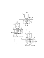
- FIG. 6 and FIG. 7 are means in the case where the cutting die D according to the present invention does not have the vertical movement mechanism.
- the cutting die D according to the present invention usually has a vertical movement mechanism such as a cylinder below it, and descends when moving the work W so that the cutting tip 50 separates from the work W
- the workpiece W is cut by the cutting tip 50 by not damaging the back surface and rising at the time of processing the workpiece W.
- FIG. 6 and 7 show simple vertical moving means instead of the vertical moving mechanism, the former using the ejector plate 60 and the latter using the air A of the discharge mechanism 52 (FIG. 5 (B)). It is a thing.
- rollers 57, 58 are rotatably provided on both sides of the cutting tip 50 (FIG. 6B) and on the ejector plate 60, and the work W is placed on the rollers 57, 58. It is done.
- the work W is not pressed and moves along the pass line PL, and the ejector plate 60 is moved by the spring 43 through which the bolt 42 passes.
- the cutting tip 50 is urged upward, and the cutting tip 50 does not contact the work W, and the back surface thereof is not scratched.
- the cutting punch P descends and presses the workpiece W, so the workpiece W descends together with the ejector plate 60 and moves while being in contact with the cutting tip 50 to cut such as V-groove processing Processing is performed.
- the housing 36 to which the cutting tip 50 (FIG. 7 (A)) is fixed is rotatably provided in the discharge hole 39, and the whole is inclined rearward by the weight of the cutting tip 50. By doing this, when the workpiece W is moved, the whole including the cutting tip 50 is immersed in the discharge hole 39.
- the work W is not pressed by the cutting punch P at the upper limit position, moves along the pass line PL, and the back surface thereof is not scratched.
- the air hole 56 constituting the discharge mechanism 52 shown in FIG. 5 is provided at the rear position of the housing 36, and the air A jetted from the air hole 56 toward the discharge hole 39 Since the lower part of the body 36 (FIG. 7 (B)) is hit, the casing 36 stands upright by rotating clockwise, and the cutting tip 50 contacts the work W.
- FIG. 8 shows the present invention (the case of the cutting die D according to the present invention (described above (FIGS. 1 to 7) and the cutting method according to the present invention described later (FIGS. 9 to 20)) Is a view showing a turret punch press among the punch presses to which the present invention is applied, the turret punch press has an upper turret 6 and a lower turret 7 as described above (FIG. 1).
- a mold comprising the die D for cutting work (FIG. 1) according to the present invention and the punch P for cutting working in cooperation therewith, and various other punching and forming work etc.
- Dies consisting of a punch P and a die D are arranged concentrically.
- the single-sided type cutting tip 50 (FIG. 1) to be used when implementing the cutting method (for example, FIG. 14) according to the present invention. Since the direction of (corresponding) can be automatically changed, machining can be performed in a reciprocating state by moving the workpiece W back and forth, and the machining time can be shortened.
- the chains 4 and 5 are respectively wound around the rotation shaft 8 of the upper turret 6 and the rotation shaft 9 of the lower turret 7, and the chains 4 and 5 are wound around the drive shaft 3, and Just above the punch P at the processing position K, as described above (FIG. 1), the upper frame 1 is provided with a ram striker 2, for example, which strikes the cutting punch P and pushes down the entire punch P. It is done.
- a ram striker 2 for example
- a Y-axis LM guide rail 17 is laid on the lower frame 21 (FIG. 8 (B)) of the turret punch press, and a support bracket 16 is slidingly coupled to the Y-axis LM guide rail 17.
- a carriage base 11 is mounted on the bracket 16, and a ball screw 14 of a Y-axis motor My provided on the upper frame 1 is screwed on the carriage base 11,
- a carriage 12 to which a clamp 13 is attached is slidably coupled to an X-axis LM guide rail (not shown) on the carriage base 11, and an X-axis motor Mx (see FIG.
- the ball screw 15 of (A) is screwed.
- a center table 10 is fixed at the center of the turret punch press, and side tables 10A and 10B are disposed on both sides of the fixed table 10, and the side tables 10A and 10B are attached to the support bracket 16. ing.
- the work W held by 13 (FIG. 1) is positioned at the processing position K, and if the work W is moved on the cutting tip 50 as it is, cutting such as V groove processing by the cutting die D according to the present invention It can be performed.
- the die D for cutting according to the present invention shown in FIGS. 1 to 7 has the cooling mechanism 51 and extends the life by preventing the wear of the cutting tip.
- the cutting method according to the invention (FIGS. 9 to 16) is gradually deepening at the start of processing by devising how to use the cutting tip 50 (for example, without performing V groove processing suddenly (FIG. 9A))
- the V-shaped groove g1 is processed, and thereafter, the V-shaped groove G having a predetermined depth H is processed by a predetermined length L1 and, at the end of the processing, the V-shaped groove g2 which is gradually shallowed is processed to obtain the cutting tip 50 Relieves the resistance received from the work W and, similarly, prolongs the life by preventing wear of the cutting tip.
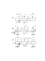
- FIG. 9 shows a cutting method using the cutting tip 50 to perform V-groove processing only once.
- FIG. 9 (A) is a first method, using the same cutting tip 50 from the processing start to the end, processing the V groove g1 gradually deepening at the processing start, and thereafter, a certain depth
- the V groove G of H is processed by a predetermined length dimension L1, and at the end of the processing, a V groove g2 which is gradually shallowed is processed.
- the cutting tip 50 receives less resistance from the workpiece W than when the cutting tip 50 is suddenly subjected to V-groove processing, whereby the wear of the cutting tip is prevented, which results in a longer life. Is extended (the same applies to FIG. 9 (B) to FIG. 9 (C)).
- the work W is moved to the left side simultaneously with the start of processing (FIG. 10 (A)), and the cutting punch P is gradually lowered to make contact with the work W.
- the cutting tip 50 bites into the workpiece W gradually.
- the V groove G having a predetermined depth H is processed by a predetermined length dimension L1.
- the workpiece W portions A and B including the V groove g1 (FIG. 9A, FIG. 10B) which becomes gradually deeper and the V groove g2 which becomes gradually shallow have no value as a product.
- the workpiece W is cut, and only the work W portion of a predetermined length L1 on which the V groove G having the predetermined depth H is formed is left as a product.
- FIG. 11 is a view showing another embodiment of FIG. 9 (A), and the difference from FIG. 10 (A) is that the cutting die D is gradually raised at the start of processing, and at the end of processing The point is to gradually lower the cutting die D
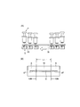
- FIG. 9B shows a second method, which uses a means different from the cutting tip 50 in advance at the start of processing and at the end of processing, and the V groove g3 gradually becomes shallower and the V groove g4 gradually shallows. Is machined, and then, using the same cutting tip 50, the entire workpiece W portion E (FIG. 12A) having the V groove g3 gradually shallower and the V groove g4 gradually deepened as both ends is constant.
- a V-shaped groove G having a depth H is machined by a predetermined length L2.
- V gradually becomes shallower at the cutting edge d3 by using means different from the cutting tip 50 in advance, for example, using the upward forming die D 'of FIG.
- the groove g3 is processed with the V groove g4 which is gradually deepened by the cutting edge d4.
- V of a constant depth H is applied to all the workpiece W portions E (FIG. 12A) having the V groove g3 gradually shallower and the V groove g4 gradually deepened at both ends.
- the groove G is processed by a predetermined length L2.
- a V-groove G having a predetermined depth H is processed by a predetermined length L2 in the entire work W portion E having the V-groove g3 (FIG. 12A) and the V-groove g4 at both ends.
- the V groove g3 (FIG. 9 (B)) which becomes gradually shallow and the V groove g4 which becomes gradually deeper become part of the V groove G having a predetermined depth H, so
- the length dimension L2 part is all valuable as a product and remains as a product.
- FIG. 9C shows a third method in which the width gradually becomes wider as the cut C1 gradually becomes narrower by using means different from the cutting tip 50 in advance at the start of processing and at the end of processing.
- Each cut C2 is processed, and then, using the same cutting tip 50, a V-groove G having a predetermined depth H is set to a predetermined length in a work W portion F (FIG. 13) between two cuts C1 and C2 Process only L3.
- the cut C1 (FIG. 13) whose width is gradually narrowed by using, for example, laser processing or a punching die using means other than the cutting tip 50 in advance at the start of processing and at the end of processing.
- the cut C2 which becomes wide in each is processed.
- a V-groove G having a predetermined depth H is machined to a predetermined length L3 in the workpiece W portion F (FIG. 13) between the two cuts C1 and C2.
- the workpiece W portions C and D including the two cuts C1 and C2 are cut off because they have no value as a product, and the predetermined length dimension L3 in which the V groove G having the predetermined depth H is formed Leave only the work W part as a product.
- FIG. 14 shows a cutting method according to the present invention in which V-groove processing is performed a plurality of times
- FIG. 14 (A) is a first method
- FIG. 14 (B) is a second method
- FIG. FIG. 14D shows the third method
- FIG. 14D shows the fourth method.
- the chip center CC is aligned with the V-groove center VC to be obtained, and the cutting depths h1, h2, h3 are made deeper for each process.
- the cutting tip 50 receives less resistance from the work W as compared with the case where the cutting tip 50 suddenly cuts a desired V-groove at one time.
- the life was extended by preventing wear (the same applies to FIGS. 14 (B) to 14 (D)).
- the hatched portion indicates the portion processed in the relevant process
- the V-groove center VC indicates the center of the target V-groove V3
- the tip center CC indicates the center of the cutting tip 50 to be used (( The same applies to FIG. 14 (B) to FIG. 14 (D)).
- FIG. 14 (A), (1), (2), and (3) respectively show the first step, the second step, and the third step (see also FIGS. 14 (B) to 14 (D)). the same).
- FIG. 14A the same cutting tip 50 is used, and V groove processing is performed by cutting the same length dimension L (for example, FIG.
- a cutting method in a turret punch press (FIG. 8) is performed.
- the chip center CC is offset in any of the left and right directions with respect to the V-groove center VC to be obtained to perform cutting.
- the first V-groove V1 is formed by offsetting the chip center CC with respect to the V-groove center VC, for example, to the left, and cutting with the cutting tip 50. It is processed.
- the chip center CC is offset to a position opposite to the offset position of (1) with respect to the V-groove center VC, that is, to the right. Do.
- the chip center CC is aligned with the V-groove center VC to be obtained, and cutting is performed deeper than the above (1) and (2).
- the groove V3 is formed.
- the chip center CC is offset in any of the left and right directions with respect to the V-groove center VC to be obtained to perform cutting.
- the first V-groove V1 is formed by offsetting the chip center CC with respect to the V-groove center VC, for example, to the left and performing cutting with the cutting tip 50. It is processed.
- the chip center CC is offset to a position opposite to the offset position of (1) with respect to the V-groove center VC, that is, to the right.
- the cutting is performed deeper than the above (1) so that a V groove V2 having an oblique side coincident with one oblique side of the V groove V1 of the above (1), for example, the left oblique side is formed.
- the chip center CC is aligned with the V-groove center VC to be obtained, and cutting is performed deeper than the above (1) and (2). Form the V groove V3.
- the chip center CC is aligned with the V-groove center VC to be obtained to perform cutting.
- the first V-groove V1 is processed by cutting with the cutting tip 50 in a state where the chip center CC is aligned with the V-groove center VC. Ru.
- the chip center CC is offset to a position in the left-right direction with respect to the V-groove center VC, that is, to the right position.
- the cutting is performed deeper than the above (1) so as to form a V-groove V2 having an oblique side coincident with one of the oblique sides, for example, the left oblique side.
- the chip center CC is aligned with the V-groove center VC to be obtained, and cutting is performed deeper than the above (1) and (2).
- the V groove V3 is formed.
- 15 and 16 show a cutting tip 50 used in the cutting method according to the present invention described in FIG.
- This cutting tip 50 is a double-sided type cutting tip having no clearance angle ⁇ (FIG. 2), and is placed in the opposite direction which is the direction in which it is not cut (for example, 1 ° to 8 ° in FIG. 15).
- the die D is attached to D, and the cutting method according to the present invention shown in FIG. 14 is performed.
- the double-sided type cutting tip 50 (FIG. 15) in the reverse direction and using it, the chips W1 can be finely divided, and clogging of the chips W1 can be prevented.
- the tool insertion hole 53 in this case is provided on the side of the shaft portion 37 B of the hexagonal holed bolt which is the fixing means 37.
- FIG. 16 shows a work by using the cutting die D in which the rotatably mounted double-sided type cutting tip 50 is switched to lie in the reverse direction which is the direction that can not be cut in accordance with the moving direction of the work W in contact therewith. It is a case where cutting is performed by repeating W going back.
- V-groove processing is performed by overlapping the same length dimension, so the processing time tends to be long.
- the housing 36 to which the double-sided type cutting tip 50 is attached is rotatably provided with respect to the cutting die D, and a stopper is provided near the lower portion of the housing 36. 61 are provided.
- FIG. 16 is intended to shorten the processing time of the cutting method according to the present invention by using the cutting die D to which the double-sided type cutting tip 50 is attached.
- the present invention is used for cutting dies and cutting methods having an extended life by preventing wear of the cutting tips, and the cutting tips are used for all cutting operations such as V grooving and deburring. Furthermore, the present invention is applicable not only to a single punch press in which a pair of molds is disposed but also to a turret punch press having an upper turret and a lower turret in which a plurality of pairs of molds are disposed, which is extremely useful.
Landscapes
- Engineering & Computer Science (AREA)
- Mechanical Engineering (AREA)
- Punching Or Piercing (AREA)
Abstract
L'invention porte sur une matrice de coupe (D), qui a une pointe de coupe (50), qui est utilisée dans une poinçonneuse et qui sert à usiner une pièce (W) en coopération avec un poinçon de coupe (P), laquelle comporte un mécanisme de refroidissement (51) pour refroidir la pointe de coupe (50). Le mécanisme de refroidissement (51) est configuré à partir d'une rainure périphérique (54), située sur la circonférence du corps de matrice (41) pour fournir de l'air (A) à partir de l'extérieur, et de trous d'air (55) qui communiquent avec la rainure circonférentielle (54) et qui servent à projeter de l'air (A) vers la pointe de coupe (50).
Applications Claiming Priority (2)
| Application Number | Priority Date | Filing Date | Title |
|---|---|---|---|
| JP2013-047065 | 2013-03-08 | ||
| JP2013047065A JP6060433B2 (ja) | 2013-03-08 | 2013-03-08 | 切削加工用ダイ及び切削加工方法 |
Publications (1)
| Publication Number | Publication Date |
|---|---|
| WO2014136304A1 true WO2014136304A1 (fr) | 2014-09-12 |
Family
ID=51490850
Family Applications (1)
| Application Number | Title | Priority Date | Filing Date |
|---|---|---|---|
| PCT/JP2013/077703 Ceased WO2014136304A1 (fr) | 2013-03-08 | 2013-10-11 | Matrice de coupe et procédé de coupe |
Country Status (2)
| Country | Link |
|---|---|
| JP (1) | JP6060433B2 (fr) |
| WO (1) | WO2014136304A1 (fr) |
Cited By (3)
| Publication number | Priority date | Publication date | Assignee | Title |
|---|---|---|---|---|
| WO2019029935A1 (fr) * | 2017-08-10 | 2019-02-14 | Trumpf Werkzeugmaschinen Gmbh + Co. Kg | Outil et procédé pour l'usinage de pièces en forme de plaque, notamment des tôles |
| CN111545631A (zh) * | 2020-06-24 | 2020-08-18 | 深圳市国祥鑫精密模具有限公司 | 一种冷冲压加工半导体引线框架模具 |
| EP3769890A1 (fr) * | 2019-07-25 | 2021-01-27 | PASS Stanztechnik AG | Procédé de coupe d'un évidement en forme de rainure dans une pièce |
Families Citing this family (2)
| Publication number | Priority date | Publication date | Assignee | Title |
|---|---|---|---|---|
| JP2016094974A (ja) * | 2014-11-13 | 2016-05-26 | 透一 野渡 | 溝付き部材の製造方法 |
| JP6718329B2 (ja) * | 2015-07-30 | 2020-07-08 | 株式会社アマダ | ワーク掴み替え切削加工方法 |
Citations (5)
| Publication number | Priority date | Publication date | Assignee | Title |
|---|---|---|---|---|
| JPS62297044A (ja) * | 1986-06-17 | 1987-12-24 | Daido Steel Co Ltd | バイトホルダ− |
| JPH02114446U (fr) * | 1989-02-27 | 1990-09-13 | ||
| JPH0557687A (ja) * | 1991-09-02 | 1993-03-09 | Hitachi Ltd | セラミツクグリ−ンシ−ト穴明け用工具 |
| JP4471248B2 (ja) * | 2000-08-02 | 2010-06-02 | 株式会社アマダ | 金型装置 |
| JP2011079061A (ja) * | 2003-05-20 | 2011-04-21 | Amada Co Ltd | ダイ工具 |
-
2013
- 2013-03-08 JP JP2013047065A patent/JP6060433B2/ja active Active
- 2013-10-11 WO PCT/JP2013/077703 patent/WO2014136304A1/fr not_active Ceased
Patent Citations (5)
| Publication number | Priority date | Publication date | Assignee | Title |
|---|---|---|---|---|
| JPS62297044A (ja) * | 1986-06-17 | 1987-12-24 | Daido Steel Co Ltd | バイトホルダ− |
| JPH02114446U (fr) * | 1989-02-27 | 1990-09-13 | ||
| JPH0557687A (ja) * | 1991-09-02 | 1993-03-09 | Hitachi Ltd | セラミツクグリ−ンシ−ト穴明け用工具 |
| JP4471248B2 (ja) * | 2000-08-02 | 2010-06-02 | 株式会社アマダ | 金型装置 |
| JP2011079061A (ja) * | 2003-05-20 | 2011-04-21 | Amada Co Ltd | ダイ工具 |
Cited By (5)
| Publication number | Priority date | Publication date | Assignee | Title |
|---|---|---|---|---|
| WO2019029935A1 (fr) * | 2017-08-10 | 2019-02-14 | Trumpf Werkzeugmaschinen Gmbh + Co. Kg | Outil et procédé pour l'usinage de pièces en forme de plaque, notamment des tôles |
| EP3769890A1 (fr) * | 2019-07-25 | 2021-01-27 | PASS Stanztechnik AG | Procédé de coupe d'un évidement en forme de rainure dans une pièce |
| CN112296445A (zh) * | 2019-07-25 | 2021-02-02 | 帕斯冲压技术股份公司 | 用于向工件中切削槽形凹部的方法 |
| US11583944B2 (en) | 2019-07-25 | 2023-02-21 | Pass Stanztechnik Ag | Method for cutting a groove-shaped recess into a workpiece |
| CN111545631A (zh) * | 2020-06-24 | 2020-08-18 | 深圳市国祥鑫精密模具有限公司 | 一种冷冲压加工半导体引线框架模具 |
Also Published As
| Publication number | Publication date |
|---|---|
| JP6060433B2 (ja) | 2017-01-18 |
| JP2014172073A (ja) | 2014-09-22 |
Similar Documents
| Publication | Publication Date | Title |
|---|---|---|
| JP5939001B2 (ja) | ドリル | |
| JP6060433B2 (ja) | 切削加工用ダイ及び切削加工方法 | |
| JP2017100193A (ja) | 縦型旋盤 | |
| JP6568970B2 (ja) | 切削加工用金型 | |
| JP6302032B2 (ja) | 切削加工用ダイ及び切削加工方法 | |
| CN210908134U (zh) | 一种方便换刀的机床刀架 | |
| KR20120066625A (ko) | 드릴링 공구 | |
| JP2021020313A (ja) | 溝形凹部を工作物に切削する方法 | |
| CN216100010U (zh) | 一种清除高频电路板上深槽槽底毛刺的切削工装 | |
| EP1574274A3 (fr) | Méthode de production de surface de couplage entaillée d'un porte-outil et surface de couplage entaillée | |
| KR20200025029A (ko) | 자동변속기 시프트 파이프의 디버링장치 | |
| JP5651353B2 (ja) | シェービング金型 | |
| CN211939168U (zh) | 铜冷却壁三连环相割孔加工刀具组件 | |
| CN202438909U (zh) | 珩磨头的双进给机构 | |
| JP3893119B2 (ja) | テーパ加工方法及びその装置 | |
| JP4349868B2 (ja) | ブローチ及びブローチ装置 | |
| CN110539018A (zh) | 铜冷却壁三连环相割孔加工刀具及加工工艺 | |
| CN118768943B (zh) | 一种数控加工中心的切磨装置及其工作方法 | |
| CN219818777U (zh) | 油缸耳环铣钻割专用机 | |
| CN220698026U (zh) | 一种外形和内孔冲毛边装置 | |
| JP2018167313A (ja) | 面取り加工方法及び金型 | |
| CN103480894B (zh) | 加工盐芯用铣钻一体刀具 | |
| CN212577587U (zh) | 一种便于车床打孔的进料装置 | |
| CN214922572U (zh) | 一种数控钻攻机用轴类切削工装夹具 | |
| CN102091795A (zh) | 粗精一体化舍弃式镗孔刀具 |
Legal Events
| Date | Code | Title | Description |
|---|---|---|---|
| 121 | Ep: the epo has been informed by wipo that ep was designated in this application |
Ref document number: 13877260 Country of ref document: EP Kind code of ref document: A1 |
|
| NENP | Non-entry into the national phase |
Ref country code: DE |
|
| 122 | Ep: pct application non-entry in european phase |
Ref document number: 13877260 Country of ref document: EP Kind code of ref document: A1 |