WO2014136363A1 - Procédé de fabrication et dispositif de fabrication - Google Patents
Procédé de fabrication et dispositif de fabrication Download PDFInfo
- Publication number
- WO2014136363A1 WO2014136363A1 PCT/JP2013/085000 JP2013085000W WO2014136363A1 WO 2014136363 A1 WO2014136363 A1 WO 2014136363A1 JP 2013085000 W JP2013085000 W JP 2013085000W WO 2014136363 A1 WO2014136363 A1 WO 2014136363A1
- Authority
- WO
- WIPO (PCT)
- Prior art keywords
- laminated
- manufacturing
- module
- positioning
- manufacturing apparatus
- Prior art date
- Legal status (The legal status is an assumption and is not a legal conclusion. Google has not performed a legal analysis and makes no representation as to the accuracy of the status listed.)
- Ceased
Links
Images


Classifications
-
- H—ELECTRICITY
- H01—ELECTRIC ELEMENTS
- H01M—PROCESSES OR MEANS, e.g. BATTERIES, FOR THE DIRECT CONVERSION OF CHEMICAL ENERGY INTO ELECTRICAL ENERGY
- H01M8/00—Fuel cells; Manufacture thereof
- H01M8/24—Grouping of fuel cells, e.g. stacking of fuel cells
- H01M8/2465—Details of groupings of fuel cells
- H01M8/247—Arrangements for tightening a stack, for accommodation of a stack in a tank or for assembling different tanks
- H01M8/248—Means for compression of the fuel cell stacks
-
- B—PERFORMING OPERATIONS; TRANSPORTING
- B32—LAYERED PRODUCTS
- B32B—LAYERED PRODUCTS, i.e. PRODUCTS BUILT-UP OF STRATA OF FLAT OR NON-FLAT, e.g. CELLULAR OR HONEYCOMB, FORM
- B32B38/00—Ancillary operations in connection with laminating processes
- B32B38/18—Handling of layers or the laminate
- B32B38/1808—Handling of layers or the laminate characterised by the laying up of the layers
-
- H—ELECTRICITY
- H01—ELECTRIC ELEMENTS
- H01M—PROCESSES OR MEANS, e.g. BATTERIES, FOR THE DIRECT CONVERSION OF CHEMICAL ENERGY INTO ELECTRICAL ENERGY
- H01M8/00—Fuel cells; Manufacture thereof
- H01M8/24—Grouping of fuel cells, e.g. stacking of fuel cells
- H01M8/2404—Processes or apparatus for grouping fuel cells
-
- H—ELECTRICITY
- H01—ELECTRIC ELEMENTS
- H01M—PROCESSES OR MEANS, e.g. BATTERIES, FOR THE DIRECT CONVERSION OF CHEMICAL ENERGY INTO ELECTRICAL ENERGY
- H01M8/00—Fuel cells; Manufacture thereof
- H01M8/24—Grouping of fuel cells, e.g. stacking of fuel cells
- H01M8/2465—Details of groupings of fuel cells
- H01M8/247—Arrangements for tightening a stack, for accommodation of a stack in a tank or for assembling different tanks
-
- B—PERFORMING OPERATIONS; TRANSPORTING
- B32—LAYERED PRODUCTS
- B32B—LAYERED PRODUCTS, i.e. PRODUCTS BUILT-UP OF STRATA OF FLAT OR NON-FLAT, e.g. CELLULAR OR HONEYCOMB, FORM
- B32B2457/00—Electrical equipment
- B32B2457/18—Fuel cells
-
- H—ELECTRICITY
- H01—ELECTRIC ELEMENTS
- H01M—PROCESSES OR MEANS, e.g. BATTERIES, FOR THE DIRECT CONVERSION OF CHEMICAL ENERGY INTO ELECTRICAL ENERGY
- H01M8/00—Fuel cells; Manufacture thereof
- H01M8/10—Fuel cells with solid electrolytes
- H01M2008/1095—Fuel cells with polymeric electrolytes
-
- Y—GENERAL TAGGING OF NEW TECHNOLOGICAL DEVELOPMENTS; GENERAL TAGGING OF CROSS-SECTIONAL TECHNOLOGIES SPANNING OVER SEVERAL SECTIONS OF THE IPC; TECHNICAL SUBJECTS COVERED BY FORMER USPC CROSS-REFERENCE ART COLLECTIONS [XRACs] AND DIGESTS
- Y02—TECHNOLOGIES OR APPLICATIONS FOR MITIGATION OR ADAPTATION AGAINST CLIMATE CHANGE
- Y02E—REDUCTION OF GREENHOUSE GAS [GHG] EMISSIONS, RELATED TO ENERGY GENERATION, TRANSMISSION OR DISTRIBUTION
- Y02E60/00—Enabling technologies; Technologies with a potential or indirect contribution to GHG emissions mitigation
- Y02E60/30—Hydrogen technology
- Y02E60/50—Fuel cells
-
- Y—GENERAL TAGGING OF NEW TECHNOLOGICAL DEVELOPMENTS; GENERAL TAGGING OF CROSS-SECTIONAL TECHNOLOGIES SPANNING OVER SEVERAL SECTIONS OF THE IPC; TECHNICAL SUBJECTS COVERED BY FORMER USPC CROSS-REFERENCE ART COLLECTIONS [XRACs] AND DIGESTS
- Y02—TECHNOLOGIES OR APPLICATIONS FOR MITIGATION OR ADAPTATION AGAINST CLIMATE CHANGE
- Y02P—CLIMATE CHANGE MITIGATION TECHNOLOGIES IN THE PRODUCTION OR PROCESSING OF GOODS
- Y02P70/00—Climate change mitigation technologies in the production process for final industrial or consumer products
- Y02P70/50—Manufacturing or production processes characterised by the final manufactured product
Definitions
- the present invention relates to a manufacturing method and a manufacturing apparatus that embodies the manufacturing method.
- a fuel cell is configured by alternately laminating separators and membrane electrode assemblies. Since the fuel cell can obtain a high output according to the number of laminated layers of the separator and the membrane electrode assembly, it is desirable to increase the number of laminated layers.
- the positions of the separators to be stacked are relatively shifted, for example, the anode gas, cathode gas, and cooling water through-holes provided in the separator do not coincide with each other between the adjacent separators. Battery performance cannot be achieved.
- the two positioning holes provided in the laminated member are:
- the two positioning members are not smoothly inserted.
- the positioning hole of the laminated member and the tip of the positioning member interfere locally, and there is a possibility that the laminated member under load is deformed.
- the present invention has been made to solve the above-described problems, and an object of the present invention is to provide a manufacturing method capable of stacking with high positioning accuracy without deforming a stacked member and a manufacturing apparatus embodying the manufacturing method.
- the manufacturing method according to the present invention that achieves the above object is a manufacturing method in which a plurality of laminated members each formed in a plate shape are laminated and manufactured while being positioned on a surface orthogonal to the laminating direction.
- This manufacturing method has a guide process and a positioning process.
- the laminated member is moved while being guided in the laminating direction in a state in which the first reference surface along the laminating direction of the laminated member is along the first positioning member arranged in the laminating direction of the laminated member.
- the second reference surface along the stacking direction of the laminated member is arranged on the second positioning member arranged in parallel with the first positioning member while the laminated member is moving along the first positioning member. Position by abutting.
- the manufacturing apparatus that achieves the above object is a manufacturing apparatus that manufactures by laminating a plurality of laminated members each formed in a plate shape while positioning each other on a plane orthogonal to the laminating direction.
- the manufacturing apparatus includes a first positioning member, a second positioning member, a moving member, and a control unit.
- the first positioning member has a long shape and is disposed on the reference table.
- the second positioning member is disposed on the reference base in parallel with the longitudinal direction of the first positioning member, and has a long shape shorter than the first positioning member.
- the moving member moves the laminated member.
- the control unit controls the operation of the moving member, and moves the first reference surface along the stacking direction of the stacked member along the first positioning member, and the second reference surface along the stacking direction of the stacked member. Is positioned while being moved along the second positioning member.
- FIG. 4 is a partial cross-sectional view taken along line 4-4 in FIG. 3, showing a state in which the module is inserted into the main pillar after being inserted into the main pillar in the manufacturing apparatus according to the first embodiment.
- FIG. 8 is a perspective view showing a state in which the steps shown in FIGS. 3 to 7 are repeated and all necessary modules are stacked in the manufacturing apparatus according to the first embodiment.
- the manufacturing apparatus which concerns on 1st Embodiment after pulling out a pillar space
- FIG. 10 is a perspective view showing various forms relating to the tip of the follower used in the steps shown in FIGS. 2 to 9 in the manufacturing apparatus according to the first embodiment. It is a perspective view which shows the various forms which position a module with respect to the main pillar with which the manufacturing apparatus which concerns on 1st Embodiment was equipped, and the follower pillar.
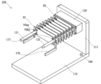
- FIG. 5 is a perspective view showing a state in which the module 10 is temporarily placed on all temporary placement spacers 141 in the manufacturing apparatus 100 and then the column interval adjusting jig 150 is inserted through the main pillar 131 and the secondary pillar 132.
- FIG. 6 is a perspective view illustrating a state in which all modules 10 temporarily placed on the temporary placement spacer 141 are sequentially moved downward and stacked in the manufacturing apparatus 100.
- FIG. 7 is a perspective view showing a state in which all the modules 10 that have been temporarily placed on the temporary spacer 141 have been stacked in the manufacturing apparatus 100 by repeating the process shown in FIG. 6.
- FIG. 8 is a perspective view showing a state in which all the necessary modules 10 have been stacked in the manufacturing apparatus 100 by repeating the steps shown in FIGS.
- FIG. 9 is a perspective view showing a state in which the second end member 30 is stacked on the uppermost module 10 after the column interval adjusting jig 150 is pulled out in the manufacturing apparatus 100.
- FIG. 10 is a perspective view showing various forms related to the distal end portion of the follower pillar 132 used in the steps shown in FIGS. 2 to 9 in the manufacturing apparatus 100.
- FIG. 11 is a perspective view showing various forms for positioning the module 10 with respect to the main pillar 131 and the follower pillar 132 provided in the manufacturing apparatus 100.
- the member indicated by the broken line is in a state before operation, and the member indicated by the solid line is in operation or is in operation. The later state is shown.
- the module 10 corresponds to a laminated member. Specifically, the module 10 is configured, for example, by laminating a plurality of separators and membrane electrode assemblies (MEAs) used in the fuel cell 1 alternately.
- the module 10 is formed in a long plate shape.
- the module 10 includes a through hole corresponding to the cathode gas supply port 10c, the cooling fluid supply port 10d, and the anode gas supply port 10e at one end in the longitudinal direction.
- the module 10 includes through holes corresponding to the anode gas discharge port 10f, the cooling fluid discharge port 10g, and the cathode gas discharge port 10h at the other end in the longitudinal direction.
- the main column 131 is inserted into the cooling fluid supply port 10d, and the follower column 132 is inserted through the cooling fluid discharge port 10g.
- the main column 131 corresponds to a first positioning member.
- the sub pillar 132 corresponds to a second positioning member.
- the first end member 20 is inserted into the main pillar 131 and the sub pillar 132, and the first end member 20 is attached to the reference base 120. It is mounted (S101 in FIG. 1).
- the reference stand 120 of the manufacturing apparatus 100 is made of, for example, metal and is formed in a rectangular parallelepiped.
- the upper part of the reference table 120 is formed smoothly because the modules 10 are stacked via the first end member 20.
- the reference table 120 has round holes at both ends in the longitudinal direction of the upper part.
- a main pillar 131 and a follower pillar 132 are detachably inserted into a round hole provided in the reference table 120.
- the main column 131 has a long shape and is disposed on the reference table 120.
- the main column 131 has a cylindrical shape and has an outer peripheral surface that is formed smoothly.
- the sub pillar 132 is arranged on the reference base 120 in parallel with the longitudinal direction of the main pillar 131 and has a long shape shorter than the main pillar 131.
- the sub pillar 132 includes a tip portion 132a having a tapered shape and a base material portion 132b extending the tip portion 132a.
- the base portion 132b of the follower 132 has a smooth outer peripheral surface.
- the reference table 120 is fixed to the upper part of the support table 110.
- the support base 110 is made of, for example, metal and is formed in a plate shape.
- the first end member 20 of the fuel cell 1 sandwiches a plurality of stacked modules 10 with a second end member 30 described later.
- the first end member 20 is made of, for example, a metal, and an insulator is provided at a portion in contact with the module 10.
- the outer shape of the first end member 20 is the same as the outer shape of the module 10.
- the first end member 20 is formed in a rectangular plate shape, and has a through hole corresponding to the cathode gas supply port 20c, the cooling fluid supply port 20d, and the anode gas supply port 20e at one end in the longitudinal direction. .
- the first end member 20 includes a through hole corresponding to the anode gas discharge port 20f, the cooling fluid discharge port 20g, and the cathode gas discharge port 20h at the other end in the longitudinal direction.
- the main column 131 is inserted into the cooling fluid supply port 20d, and the follower column 132 is inserted through the cooling fluid discharge port 20g.
- a pair of handling hands 171 and 172 corresponding to the moving member are used for conveying the first end member 20 .
- the pair of handling hands 171 and 172 each sandwich the first end member 20.
- the handling hand 171 grasps one end of the first end member 20 in the longitudinal direction
- the handling hand 172 grasps the other end of the first end member 20 in the longitudinal direction.
- the pair of handling hands 171 and 172 are movable to arbitrary positions in the horizontal and vertical directions by a three-axis moving stage (not shown).
- the lowermost temporary spacer 141 located on the downstream side in the stacking direction of the modules 10 is rotated forward 180 degrees clockwise around the rotating portion 141a, thereby stacking the modules 10. Project into the area.
- the temporary spacer 141 corresponds to a temporary member.
- the module 10 is expressed as MOD (S102 in FIG. 1).
- a plurality of temporary spacers 141 of the manufacturing apparatus 100 are provided at regular intervals with respect to the support column 142.
- the temporary placement spacer 141 is formed in a plate shape so as to place the central portion of the module 10.
- the longitudinal dimension of the temporary spacer 141 is shorter than the longitudinal dimension of the module 10.
- the short-side dimension of the temporary spacer 141 is slightly longer than the short-side dimension of the module 10.
- the temporary spacer 141 is provided so as to be rotatable with respect to the support column 142 around a rotating portion 141a provided at one end thereof.
- a plurality of temporary spacers 141 provided on the support 142 are individually rotated.
- the support column 142 is disposed perpendicular to the support table 110 so as to be adjacent to the reference table 120.
- the module 10 is lowered and the first opening 10 a of the module 10 is inserted into the main pillar 131.
- the first opening 10a corresponds to, for example, the cooling fluid supply port 10d.
- the module 10 is lowered along the main column 131 in a state where the main column 131 is in contact with the first reference surface 10aa of the first opening 10a of the module 10.
- the first reference surface 10aa is an inner surface of the first opening 10a and is provided in a plane along the stacking direction of the modules 10 (S103 in FIG. 1).
- the module 10 is further lowered, and the second opening 10b of the module 10 is inserted into the follower column 132.
- the second opening 10b corresponds to, for example, the cooling fluid discharge port 10g.
- the module 10 is lowered along the follower column 132 in a state where the follower column 132 is in contact with the second reference surface 10bb of the second opening 10b of the module 10.
- the second reference surface 10bb is an inner surface of the second opening 10b and is provided in a plane along the stacking direction of the modules 10 (S104 in FIG. 1).
- the module 10 is further lowered and temporarily placed on the temporary placement spacer 141 (S105 in FIG. 1).
- a pair of handling hands 173 and 174 corresponding to moving members are used for conveying the module 10.
- the pair of handling hands 173 and 174 each sandwich the module 10.
- the handling hand 171 grasps one end of the module 10 in the longitudinal direction
- the handling hand 172 grasps the other end in the longitudinal direction of the module 10.
- the pair of handling hands 173 and 174 are movable to arbitrary positions in the horizontal and vertical directions by a three-axis moving stage (not shown).
- the controller 180 corresponds to a control unit, controls the operation of the handling hands 173 and 174, and moves the first reference plane 10aa along the stacking direction of the modules 10 along the main pillar 131.
- the second reference surface 10bb along the stacking direction of 10 is positioned along the follower pillar 132 while being moved.
- the controller 180 includes a ROM, a CPU, and a RAM.
- ROM Read Only Memory
- a CPU Central Processing Unit
- a RAM Random Access Memory
- the area indicated by A in FIG. 4A corresponds to the guide unit 101.
- the module 10 is lowered so as to approach the main pillar 131 while being inclined downward from the main pillar 131 toward the sub pillar 132.
- the module 10 is inclined in the counterclockwise direction in the drawing when the first opening 10 a is brought into contact with the main pillar 131.
- the module 10 moves along the main pillar 131 in a state where the first reference surface 10aa of the first opening 10a is in contact with the main pillar 131, the module 10 is adjusted from an inclined state to a horizontal state.
- the thickness of the module 10 increases, the area where the first reference surface 10aa of the first opening 10a contacts the main pillar 131 increases, and the inclination of the module 10 can be easily adjusted.
- the area indicated by B in FIG. 4A corresponds to the positioning unit 102.
- the second opening 10 b of the module 10 is inserted into the follower 132.
- the sub pillar 132 includes a tip portion 132a having a tapered shape, and a base material portion 132b having a cylindrical shape extending from the tip portion 132a.
- the tip of the tapered shape is in the process of moving while contacting the front end 132a of the follower pillar 132. Since it is guided to the portion 132a, the angle error can be eliminated.
- the module 10 shown in FIG. 4B is so approached to the main column 131 that it is inclined downward from the follower column 132 toward the main column 131 in the guide portion 101. Lower.
- the module 10 is inclined in the clockwise direction in the drawing when the first opening 10a abuts the main pillar 131.
- the module 10 extends along the main column 131 in a state where the first reference surface 10aa of the first opening 10a is in contact with the main column 131. Since it moves, it is adjusted from an inclined state to a horizontal state.
- the second opening 10b of the module 10 is inserted into the follower pillar 132.
- the tip of the tapered shape is in the process of moving while contacting the front end 132a of the follower pillar 132. Since it is guided to the portion 132a, the angle error can be eliminated.
- the modules 10 are temporarily placed in order. That is, the steps S102 to S105 in FIG. 1 are repeated until the module 10 is temporarily placed in all the temporarily placeable spacers (S106 in FIG. 1).
- the column interval adjusting jig 150 for positioning the relative position of the main column 131 and the sub column 132 is inserted into the main column 131 and the sub column 132, respectively.
- the column interval adjusting jig 150 is installed on top of the pair of reference side columns 161 and 162 provided close to both ends in the longitudinal direction of the reference table 120 (S107 in FIG. 1).
- the column interval adjusting jig 150 of the manufacturing apparatus 100 corresponds to a holding member.
- the column interval adjusting jig 150 is made of, for example, metal and is formed in a plate shape. At both ends in the longitudinal direction of the column interval adjusting jig 150, there are provided a first reference hole 150a and a second reference hole 150b formed of through holes.
- a first reference hole 150a and a second reference hole 150b formed of through holes.
- the pair of reference side columns 161 and 162 are arranged on the support base 110 so as to be close to both ends of the reference base 120 in the longitudinal direction.
- the pair of reference side columns 161 and 162 are made of, for example, metal and are formed in a plate shape with a large opening inside.
- a pair of handling hands 175 and 176 corresponding to moving members are used for transporting the column interval adjusting jig 150.
- the pair of handling hands 175 and 176 respectively hold the column interval adjusting jig 150.
- the handling hand 171 grasps one end in the longitudinal direction of the column interval adjusting jig 150, and the handling hand 172 grasps the other end in the longitudinal direction of the column interval adjusting jig 150.
- the pair of handling hands 175 and 176 are movable to arbitrary positions in the horizontal and vertical directions by a three-axis moving stage (not shown).
- the temporary spacer 141 temporarily placing the module 10 is 180 degrees centering on the rotating portion 141a. Reverse counterclockwise. As a result, the temporary spacer 141 is retracted from the stacked region of the module 10 (S108 in FIG. 1). Next, the module 10 in which the temporary spacer 141 is retracted and moved is moved downward and stacked (S109 in FIG. 1).
- the second end member 30 is inserted into the main column 131 and the sub column 132, respectively, and the second end member 30 is stacked on the uppermost module 10 (S113 in FIG. 1).
- the second end member 30 of the fuel cell 1 sandwiches a plurality of stacked modules 10 with the first end member 20.
- the second end member 30 is made of, for example, a metal, and an insulator is provided at a portion in contact with the module 10.
- the outer shape of the second end member 30 is the same as the outer shape of the module 10.
- the second end member 30 is formed in a long plate shape, and has a through hole corresponding to the cathode gas supply port 30c, the cooling fluid supply port 30d, and the anode gas supply port 30e at one end in the longitudinal direction. .
- the second end member 30 includes a through hole corresponding to the anode gas discharge port 30f, the cooling fluid discharge port 30g, and the cathode gas discharge port 30h at the other end in the longitudinal direction.
- the main column 131 is inserted into the cooling fluid supply port 30d, and the follower column 132 is inserted through the cooling fluid discharge port 30g.
- a pair of handling hands 171 and 172 are used for transporting the second end member 30.
- the pair of handling hands 171 and 172 each sandwich the second end member 30.
- the handling hand 171 grasps one end in the longitudinal direction of the second end member 30, and the handling hand 172 grasps the other end in the longitudinal direction of the second end member 30.
- the pair of handling hands 171 and 172 are movable to arbitrary positions in the horizontal and vertical directions by a three-axis moving stage (not shown).
- the tip of the follower column 132 used in the steps shown in FIGS. 2 to 9 can have various configurations.
- the tip portion 132a may be formed in a truncated cone shape.
- the tip portion 132a shown in FIG. 10A corresponds to the tip portion 132a shown in FIGS.
- the tip end portion 132c may be formed in a conical shape.
- the follower column 132 includes a tip portion 132c formed in a truncated cone shape, and a base material portion 132d that extends from the tip portion 132c and has a cylindrical shape.
- the tip end portion 132e may be formed in a multistage shape.
- the sub pillar 132 includes a tip portion 132e formed in a multi-stage shape, and a base material portion 132f that extends from the tip portion 132e and has a cylindrical shape.
- the tip portion 132g having a truncated cone shape may be formed so as to be separable from the base material portion 132h having a cylindrical shape.
- a screw provided protruding from the lower portion of the tip end portion 132g shown in FIG. 10D is screwed into a screw groove provided in the upper surface of the base material portion 132h.
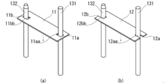
- the main pillar 131 and the secondary pillar 132 used in the steps shown in FIGS. 2 to 9 can position the modules 10 formed in various shapes as shown in FIG.
- the main pillar 131 is formed with respect to the first opening portion 11a and the second opening portion 11b opened near both ends in the longitudinal direction of the module 11.
- And follower pillars 132 are inserted and moved respectively.
- the first reference surface 11aa is an inner surface of the first opening 11a and is provided in a plane along the stacking direction of the modules 11.
- the second reference surface 11bb is an inner surface of the second opening 11b and is provided in a plane along the stacking direction of the modules 11.
- the module 12 having a form corresponding to FIG. 11B may be used.
- the main pillar 131 and the secondary pillar 132 are arranged along the first notch 12a and the second notch 12b formed by notching the outer periphery of both ends of the module 12 in the longitudinal direction. Move them.
- the first reference surface 12aa is an inner surface of the first cutout portion 12a and is provided in a surface along the stacking direction of the modules 12.
- the second reference surface 12bb is an inner surface of the second notch 12b and is provided in a surface along the stacking direction of the modules 12.
- the manufacturing method according to the first embodiment described above and the manufacturing apparatus 100 that embodies the manufacturing method have the following operational effects.
- the manufacturing method according to the first embodiment is a manufacturing method in which a plurality of modules 10 each formed in a plate shape are stacked and manufactured while being positioned on a plane orthogonal to the stacking direction.
- This manufacturing method has a guide process and a positioning process.
- the module 10 is moved while being guided in the stacking direction in a state where the first reference surface 10aa along the stacking direction of the module 10 is along the main pillar 131 disposed toward the stacking direction of the module 10. .
- the positioning step while the module 10 is moving along the main pillar 131, the second reference surface 10 bb along the stacking direction of the modules 10 is brought into contact with the sub pillar 132 arranged in parallel with the main pillar 131. To position.
- the manufacturing apparatus 100 stacks and manufactures a plurality of modules 10 each formed in a plate shape while positioning each other on a plane orthogonal to the stacking direction.
- the manufacturing apparatus 100 includes a main pillar 131, a follower pillar 132, handling hands 173 and 174, and a controller 180.
- the main column 131 has a long shape and is disposed on the reference table 120.
- the sub pillar 132 is arranged on the reference base 120 in parallel with the longitudinal direction of the main pillar 131 and has a long shape shorter than the main pillar 131.
- the handling hands 173 and 174 move the module 10.
- the controller 180 controls the operations of the handling hands 173 and 174 and moves along the stacking direction of the module 10 while moving the first reference surface 10aa along the stacking direction of the module 10 along the main pillar 131.
- the second reference surface 10bb is positioned while being moved along the sub pillar 132.
- the second reference surface 10bb along the stacking direction of the modules 10 is parallel to the main column 131 while the module 10 is moving along the main column 131. Then, the positioning is performed by contacting the follower pillar 132 arranged in this manner. According to such a manufacturing method and manufacturing apparatus 100, the modules 10 can be stacked with high accuracy without being deformed.
- the positioning of the module 10 is performed with a simple configuration using the main pillar 131 and the secondary pillar 132, and complicated mechanisms and sensors are not required. Can do.
- the manufacturing method and the manufacturing apparatus 100 configured as described above, since the module 10 is not deformed, the production is not interrupted due to the deformation of the module 10, and the manufacturing efficiency can be improved.
- first reference surface 10aa and the second reference surface 10bb are respectively provided on the inner surfaces of the first opening 10a and the second opening 10b formed in the module 10, and the main pillar 131 and the secondary pillar 132 are provided in the first opening. It is good also as a structure penetrated to 10a and the 2nd opening part 10b, respectively.
- the cooling fluid supply port of the module 10 is used as the first opening 10a
- the first reference surface 10aa is provided on the inner surface of the cooling fluid supply port
- the cooling fluid discharge port of the module 10 is used as the second opening 10b. If the second reference surface 10bb is provided on the inner surface of the cooling fluid discharge port, there is no need to provide an opening.
- main pillar 131 may be configured such that the module 10 is rotatable in a direction intersecting the stacking direction with reference to the abutted first reference surface 10aa.
- the angle error is reduced by rotating the module 10 with respect to the first reference plane 10aa. Can be resolved.
- the main column 131 may be formed in a cylindrical shape or a polygonal column shape, and the first reference surface 10aa may be composed of three continuous surfaces.
- the main column 131 allows the module 10 to rotate in a state where the outer peripheral surfaces are in contact with three continuous surfaces.
- the module 10 is configured with a simple configuration in which the outer periphery of the main column 131 formed in a cylindrical shape or a polygonal column shape is brought into contact with the first reference surface 10aa including three continuous surfaces. Positioning can be performed with respect to the main column 131 by eliminating the angle error.
- the distal end of the follower pillar 132 may be configured to recede by more than the thickness of the module 10 in the stacking direction of the module 10 from the distal end of the main pillar 131. That is, in the manufacturing apparatus 100, the sub pillar 132 may be configured to be shorter than the main pillar 131 by the thickness of the module 10 or more.
- the secondary pillar 132 is brought into contact with the second reference surface 10bb of the module 10. be able to. Therefore, it is possible to reliably prevent the module 10 from being deformed.
- the follower column 132 may have a configuration in which a tip portion having a tapered shape is provided at the tip thereof.
- the module 10 that is in contact with the main pillar 131 moves while being in contact with the distal end portion 132a of the follower pillar 132 even when an angular error occurs in the direction intersecting the stacking direction.
- the angle error can be eliminated by being guided to the tapered tip portion 132a.
- tip 132a of the follower 132 may be configured to be inclined linearly outward along the stacking direction of the modules 10.
- the module 10 moves in contact with the tip portion 132a inclined in a tapered shape in the process of moving.
- the angle error can be eliminated smoothly. Therefore, the interference between the module 10 and the follower pillar 132 can be suppressed, and the stress applied to the module 10 can be greatly reduced.
- the tip 132e of the follower pillar 132 may have a multi-stage shape with a plurality of refracting parts or bent parts.
- the module 10 moves in contact with the tip portion 132e formed in a multistage shape in the process of moving.
- the angle error can be eliminated step by step. Therefore, the interference between the module 10 and the follower pillar 132 can be suppressed, and the stress applied to the module 10 can be greatly reduced.
- tip 132g of the follower 132 may be configured to be separable.
- the follower pillar 132 may include a base material part 132b having a columnar shape or a polygonal prism shape with the tip part 132a extending, and the entire length of the base material part 132b may be longer than the thickness of the module 10.
- the module 10 inserted through the follower pillar 132 can be sufficiently positioned at the base portion 132b of the follower pillar 132.
- the follower pillar 132 and the main pillar 131 may be configured to be stacked in the direction opposite to the stacking direction of the modules 10.
- the follower column 132 when the number of stacked modules 10 is increased, it can be easily handled by stacking the follower pillar 132 and the main pillar 131.
- the follower column 132 is stacked by screwing the base member portion 132h having a screw thread in the lower part thereof with respect to the substrate member 132h shown in FIG. .
- the main pillar 131 may have the same configuration as the follower pillar 132.
- the manufacturing apparatus 100 is connected to the main pillar 131 and the sub pillar 132 after the module 10 is inserted and before the stacking, and the column interval adjusting jig that holds and positions the main pillar 131 and the sub pillar 132. 150 may be further included.
- the positions of the main pillar 131 and the follower pillar 132 are positioned using the pillar interval adjusting jig 150. Lamination can be performed with higher positioning accuracy.
- the temporary placement process which temporarily places the several module 10 in the state spaced apart from each other along the lamination direction using the several temporary placement spacer 141.
- the plurality of modules 10 are temporarily placed in order from the temporary placement spacer 141 located on the downstream side in the stacking direction of the modules 10 in the temporary placement step.
- the main pillar 131 and the secondary pillar 132 are held in a positioned state by the holding step.
- the temporary placement step the temporary placement of the modules 10 is released in order from the module 10 located downstream in the stacking direction of the modules 10 and the movement of the modules 10 is resumed.
- FIG. 12 is a perspective view showing a state in which the module 10 is inserted and temporarily placed in the main pillar 131 and the secondary pillar 132 arranged in parallel in the manufacturing apparatus 200.
- the manufacturing method and the manufacturing apparatus 200 according to the modification of the first embodiment are different from the configuration of the manufacturing method and the manufacturing apparatus 100 according to the first embodiment described above in that the module 10 is suspended and moved.
- the manufacturing apparatus 200 shown in FIG. 12 holds the reference table 120 by the side plate 111 from the side with the reference table 120 rotated 90 ° clockwise from the state shown in FIG.
- the lower part of the side plate 111 is joined to the support base 112.
- the main pillar 131 and the follower pillar 132 inserted through the reference table 120 are also arranged in parallel in a state of being rotated 90 ° clockwise from the state shown in FIG.
- the module 10 conveyed using handling hands 177 and 178 corresponding to moving members is inserted into the main pillar 131 and the sub pillar 132, and the module 10 is suspended and moved.
- the handling hands 177 and 178 temporarily place the adjacent modules 10 apart from each other.
- the second end member 30 is inserted through the main pillar 131 and the sub pillar 132, and the plurality of modules 10 are brought into close contact with each other and stacked.
- the guide process and the guide unit are moved by suspending the module 10 from the main pillar 131 that has a long shape and is arranged horizontally. Further, the positioning step and the positioning portion suspend and move the module 10 with respect to the follower pillar 132 that is formed in a long shape and is horizontally disposed.
- the guide step and the positioning step may be configured to move adjacent modules 10 in a separated state.
- FIG. 13 is a flowchart illustrating a method for applying a load to the stacked modules 10 in the method for manufacturing the module 10 using the manufacturing apparatus 300.
- FIG. 14 is a perspective view showing a state in which the load applying member 310 is placed on the second end member 30, the column interval adjusting jig 150 is attached, and the module 10 is urged in the manufacturing apparatus 300.
- FIG. 15 is a perspective view showing a state in which the exterior member is attached to the module 10 or the like while the module 10 is urged by the load applying member 310 in the manufacturing apparatus 300.
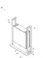
- FIG. 16 is a perspective view showing a state after the pressing member 320, the column interval adjusting jig 150, and the load applying member 310 are removed in the manufacturing apparatus 300.
- the member indicated by the broken line is in a state before operation, and the member indicated by the solid line is in operation or in operation. The later state is shown.
- the configuration of the manufacturing method and the manufacturing apparatus 300 according to the second embodiment is different from the configuration of the manufacturing method and the manufacturing apparatus 100 according to the first embodiment described above in that the load is applied to the stacked modules 10.
- the load adding step in the manufacturing method corresponds to the load adding portion of the manufacturing apparatus 300.
- a load is applied to the module 10 in which a plurality of layers are stacked as shown in FIG. 14.
- the load applying member 310 is inserted into the main pillar 131 and the follower pillar 132, and placed on the second end member 30.
- the load applying member 310 is made of, for example, metal and is formed in a plate shape.
- a first hole 310a and a second hole 310b are inserted through the main pillar 131 and the follower pillar 132 (S201 in FIG. 13).
- the column interval adjusting jig 150 is inserted into the main column 131 and the sub column 132, and is installed on the upper part of the pair of reference side columns 161 and 162 (S202 in FIG. 13).
- the pressing member 320 is inserted into the insertion hole 150 c opened in the center of the column interval adjusting jig 150 to press the load applying member 310.
- the pressing member 320 is made of, for example, metal and has a cylindrical shape (S203 in FIG. 13).
- the load applying jig 310 urges the module 10 that is stacked in plural via the second end member 30 (S204 in FIG. 13).
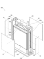
- the exterior member is attached to the plurality of stacked modules 10 and the like in a state where the plurality of stacked modules 10 are pressed by the load applying member 310 as shown in FIG.
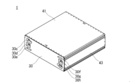
- the exterior member composed of the first main plate 41, the second main plate 42, the first side plate 43, and the second side plate 44 is attached to the first end member 20 and the second end member 30 using screws (not shown). Screw into the threaded groove provided in The first main plate 41, the second main plate 42, the first side plate 43, and the second side plate 44 are each made of a metal plate (S205 in FIG. 13).
- the pressing member 320 is pulled out from the insertion hole 150c of the column interval adjusting jig 150 and removed from the process shown in FIG. 15 (S206 in FIG. 13).
- the column interval adjusting jig 150 is pulled out and removed from the main column 131 and the sub column 132 (S207 in FIG. 13).
- the load applying member 310 is pulled out from the main pillar 131 and the sub pillar 132 and removed (S208 in FIG. 13).
- the main pillar 131 and the secondary pillar 132 are pulled out and removed from the first end member 20, the plurality of stacked modules 10, and the second end member 30 (S ⁇ b> 209 in FIG. 13).
- the manufacturing apparatus 300 includes the load application member 310 that abuts against a plurality of stacked modules 10 and applies a load to the stacking direction of the modules 10.
- a gap generated between adjacent modules 10 can be eliminated in a plurality of stacked modules 10. Therefore, when using the fuel cell 1 configured by stacking a plurality of modules 10, it is possible to prevent leakage of cooling water or the like from between adjacent modules 10. Furthermore, the resistance value between the cells of the module 10 can be reduced by sufficiently adhering the stacked modules 10.
- the load adding step may be configured to increase or decrease the load according to the repulsive force from the plurality of modules 10 to which the load is applied.
- FIG. 17 is a perspective view showing a state in which a load is applied simultaneously from above and below to a plurality of stacked modules 10 in the manufacturing apparatus 400.
- FIG. 18 is a perspective view showing a state in which a load is applied simultaneously from both ends in the horizontal direction to the plurality of stacked modules 10 in the manufacturing apparatus 400.
- FIG. 19 is a perspective view showing a state in which a load is applied to the stacked modules 10 from above before and after the top and bottom of the stacked modules 10 are reversed in the manufacturing apparatus 400.
- FIG. 20 shows a state in which a load is applied to the multi-layered module 10 from above before and after the top and bottom of the multi-layered module 10 is reversed while the load is applied in the manufacturing apparatus 400.
- FIG. 20 shows a state in which a load is applied to the multi-layered module 10 from above before and after the top and bottom of the multi-layered module 10 is reversed while the load is applied in the manufacturing apparatus 400.
- FIGS. 17 to 20 illustration of the rotation mechanism and the like is omitted, and only the minimum configuration is illustrated.
- the arrow in the figure indicates that a load is applied in the direction of the arrow.
- the manufacturing method and the manufacturing apparatus 400 according to the modified example of the second embodiment have a configuration in which a load is applied to the stacked modules 10 by a special method, and the manufacturing method and the manufacturing apparatus 300 according to the second embodiment described above. Different from the configuration.
- a pair of load applying jigs 310 are used to simultaneously apply the same or different loads to the modules 10 stacked in the vertical direction from above and below.
- the modules 10 stacked in the vertical direction are rotated in the horizontal direction, and then the horizontal ends of the modules 10 stacked in a plurality of layers are used with a pair of load applying jigs 310. Load simultaneously.
- a load is applied from above to the modules 10 stacked in a vertical direction using a pair of load applying jigs 310. Thereafter, as shown in FIG. 19B, the top and bottom of the stacked modules 10 are reversed. Further, as shown in FIG. 19 (c), a pair of load applying jigs 310 are used to apply a load from above to the modules 10 that are stacked in a reversed state.
- a load is applied from above to the modules 10 stacked in a vertical direction by using a pair of load applying jigs 310.
- FIG. 20B the top and bottom of the stacked modules 10 are reversed using a pair of load applying jigs 310 while the load is applied.
- FIG. 20 (c) a pair of load applying jigs 310 are used to apply a load from above to the modules 10 that are stacked in a reversed state.
- the load applying step simultaneously applies the same or different loads to the plurality of stacked modules 10 from above and below in the vertical direction.
- the load applying unit simultaneously applies the same or different loads to the plurality of stacked modules 10 from above and below in the vertical direction.
- a relatively large load is applied to the module 10 positioned below the module 10 due to the weight of the module 10. It is possible to prevent the load applied to the module 10 from becoming uneven.
- the spacing between adjacent modules 10 can be made uniform in the stacked modules 10.
- a load is applied from above in the vertical direction to the plurality of stacked modules 10, and then the top and bottom of the plurality of stacked modules 10 are reversed and then perpendicular to the plurality of stacked modules 10. It is good also as a structure which adds a load again from the direction upper direction.
- the interval between the modules 10 is relatively narrow due to the weight of the module 10.
- the lower module 10 that has been formed is disposed upward. That is, in the module 10 in which a plurality of modules are stacked, the module 10 positioned below the module 10 is subjected to a relatively large load due to the weight of the module 10 and the interval between the modules 10 is reduced. can do.
- the load applying step may be configured to continue applying a load to the plurality of stacked modules 10 when the top and bottom of the plurality of stacked modules 10 are reversed.
- the load applying step may be configured such that after a plurality of stacked modules 10 are arranged in the horizontal direction, a load is applied to the plurality of stacked modules 10 from both ends in the horizontal direction.
- FIG. 21 is a flowchart showing a method for inspecting the quality of the stacked modules 10 in the method for manufacturing the modules 10 using the manufacturing apparatus 500.
- FIG. 22 is a perspective view illustrating a state in which the stacked state of a plurality of stacked modules 10 is measured in the manufacturing apparatus 500.
- FIG. 23 is a perspective view showing a state in which the resistance value between a plurality of stacked modules 10 is measured in the manufacturing apparatus 500.
- FIG. 24 is a perspective view illustrating a state in which the internal volume of a plurality of stacked modules 10 is measured in the manufacturing apparatus 500.
- FIG. 25 is a perspective view showing the fuel cell 1 that has been inspected and removed from the manufacturing apparatus 500 in the manufacturing apparatus 500.
- the member indicated by the broken line is in a state before the operation, and the member indicated by the solid line is in operation or is in operation. The later state is shown.
- the configuration for inspecting the quality of the stacked modules 10 is different from the configurations of the manufacturing method and the manufacturing apparatus according to the first and second embodiments described above.
- the inspection process in the manufacturing method corresponds to the inspection unit of the manufacturing apparatus 500.
- a leak measuring device 510 corresponding to an inspection device is connected to the second end member 30 (S301 in FIG. 21).
- one medium is injected into the manifold provided in the plurality of stacked modules 10, and one medium leaking outside is measured from the gap between the adjacent modules 10 (FIG. 21).
- S302 it is determined whether or not the amount of leak is within a predetermined value. If it exceeds the predetermined value, the leak test is rejected and the process proceeds to S304. If it is within the specified value, the leak test is passed and the process goes to S305. Proceed (S303 in FIG. 21).
- the wiring 521 provided in the resistance measuring device 520 corresponding to the tester is connected to the electrode tabs 10i protruding from the modules 10 at both ends stacked in plural (S306 in FIG. 21). ).
- the resistance value of the cell between the modules 10 at the two stacked ends is measured using the resistance measuring device 520 (S307 in FIG. 21).
- an internal volume measuring device 530 corresponding to an inspection device is connected to the second end member 30 (S311 in FIG. 21).
- another medium is injected into the first manifold provided in the plurality of stacked modules 10 and discharged from the second manifold provided in the plurality of stacked modules 10.
- the discharge amount and pressure of the medium are measured (S312 in FIG. 21).
- the fuel cell 1 is removed from the manufacturing apparatus 500.
- the fuel cell 1 is configured, for example, by covering a first end member 20, a plurality of modules 10, and a second end member 30 that are stacked in this order with an exterior member.
- configurations such as an insulating plate and a current collecting plate are omitted.
- the manufacturing method according to the third embodiment includes an inspection process for inspecting the quality of a plurality of stacked modules 10.
- the manufacturing apparatus 500 according to the third embodiment includes an inspection device that is connected to a plurality of stacked modules 10 and inspects the quality of the modules 10.
- the manufacturing efficiency can be improved.
- the inspection process may be configured to measure a resistance value between a plurality of stacked modules 10 related to the fuel cell 1 using the resistance measuring device 520.
- the quality related to the resistance value of the module 10 can be inspected by measuring the resistance value between the stacked modules 10 continuously after the modules 10 are stacked. Manufacturing efficiency can be improved.
- one medium is injected into the manifold provided in the plurality of stacked modules 10 according to the fuel cell 1 using the leak measuring device 510, and one leaks to the outside through the gap between the adjacent modules 10.
- the medium may be measured.
- the inspection step uses the internal volume measuring device 530 to prepare the module 10 while injecting another medium under pressure to the first manifold provided in the plurality of stacked modules 10 according to the fuel cell 1.
- the internal volume of a plurality of stacked modules 10 may be measured based on the discharge amount and pressure of another medium discharged from the second manifold.
- FIG. 26 is a perspective view showing a state in which the process shown in FIG. 23 is performed at the end of the process shown in FIG.
- FIG. 27 is a perspective view showing a state in which the process shown in FIGS. 22 and 23 is performed at the end of the process shown in FIG.
- the manufacturing method and the manufacturing apparatus 600 according to the modified example of the third embodiment have a configuration in which the stacked module 10 is inspected in a state where a load is applied to the manufacturing method and the manufacturing apparatus 500 according to the above-described third embodiment. Different from the configuration.
- the manufacturing apparatus 600 shown in FIG. 26 performs the process shown in FIG. 23 at the end of the process shown in FIG. Specifically, the manufacturing apparatus 600 applies a resistance measuring instrument before attaching an exterior material to a plurality of stacked modules 10 or the like in a state in which a plurality of stacked modules 10 are applied using a load applying jig 310. 520 is used to measure the resistance value between the modules 10 at both ends stacked in a plurality.
- the manufacturing apparatus 600 uses a load measuring device 310 to apply a leak measurement device before attaching an exterior material to a plurality of stacked modules 10 or the like in a state where the plurality of stacked modules 10 are applied.
- the stacking state of the modules 10 stacked by using 510 is measured.
- the manufacturing apparatus 600 measures the resistance value between the modules 10 at both ends stacked by using the resistance measuring device 520.
- the inspection process inspects the quality of the module 10 in a state where a load is applied by the load addition process.
- the inspection unit inspects the quality of the module 10 in a state where a load is applied by the load addition unit.
- the quality of the module 10 is inspected before the exterior member is attached to the first end member 20, the plurality of stacked modules 10, and the second end member 30. Can do. Therefore, when there is a problem in the quality of the module 10, it is not necessary to remove the exterior member, and the module 10 can be easily repaired.
- the main column 131 corresponding to the first positioning member is inserted into the cooling fluid supply port 10d of the module 10, and the slave column 132 corresponding to the second positioning member is cooled to the module 10.
- the present invention is not limited to such a configuration.
- the main column 131 may be inserted into the cathode gas supply port 10c and the secondary column 132 may be inserted into the cathode gas discharge port 10h.
- the module 10 is provided with a long through hole, and the main pillar 131 is inserted along one end in the longitudinal direction of the through hole. It is good also as a structure inserted along the end follower pillar 132.
- FIG. The module 10 is provided with a reference surface for positioning at both ends in the longitudinal direction in a plane along the stacking direction of the long through holes.
- the main pillar 131 and the secondary pillar 132 each having a cylindrical shape with respect to the reference plane, with the three faces of the inner surfaces of the two manifold holes provided in the module 10 as the reference plane. It is not limited to the configuration along the line.
- two continuous surfaces of the inner surfaces of two manifold holes provided in the module 10 are used as a reference surface, and the outer periphery of a polygonal main column or subordinate column is set along the reference surface. It is good also as a structure.
- the two continuous surfaces serving as the reference surfaces are not limited to planar shapes, and may be, for example, a shape curved convexly toward the center of the manifold hole.
- the main pillar 131 may have a tip portion having a tapered shape at the tip, similarly to the follower pillar 132. In this case, the main pillar 131 can be easily inserted into the first opening 10 a of the module 10.
- the module 10 having a dedicated through hole for inserting the main pillar 131 and a dedicated through hole for inserting the follower pillar 132 may be used.
- the module 10 includes a reference surface for positioning in a plane along the stacking direction of the through holes.
- the laminated member to be laminated is not limited to the module 10 configured by alternately laminating a plurality of membrane electrode assemblies and separators used in the fuel cell 1.
- the laminated member is also applied to members other than the fuel cell 1.
- Fuel cell 10, 11, 12 modules (equivalent to laminated members), 10a, 11a first opening, 10aa, 11aa first reference plane, 10b, 11b second opening, 10bb, 11bb second reference plane, 10c, 20c, 30c cathode gas supply port, 10d, 20d, 30d Cooling fluid supply port, 10e, 20e, 30e anode gas supply port, 10f, 20f, 30f Anode gas outlet, 10g, 20g, 30g Cooling fluid outlet, 10h, 20h, 30h Cathode gas outlet, 10i electrode tab, 12a 1st notch part, 12aa first reference plane, 12b Second notch, 12bb second reference plane, 20 first end member, 30 second end member, 41 1st main plate, 42 second main plate, 43 first side plate, 44 second side plate, 100, 200, 300, 400, 500, 600 production equipment, 101 Guide, 102 positioning part, 110, 112 support base, 111 side plates, 120 reference table, 131 main pillar (corresponding to the following
Landscapes
- Life Sciences & Earth Sciences (AREA)
- Engineering & Computer Science (AREA)
- Manufacturing & Machinery (AREA)
- Sustainable Development (AREA)
- Sustainable Energy (AREA)
- Chemical & Material Sciences (AREA)
- Chemical Kinetics & Catalysis (AREA)
- Electrochemistry (AREA)
- General Chemical & Material Sciences (AREA)
- Fuel Cell (AREA)
- Laminated Bodies (AREA)
Abstract
L'invention vise à proposer un procédé de fabrication permettant d'effectuer une stratification à un haut niveau de précision d'alignement sans déformation des composants à stratifier. A cet effet, le procédé de fabrication selon l'invention consiste en un procédé permettant de fabriquer un stratifié par la stratification d'une pluralité de composants à stratifier respectivement en forme de plaque, en positionnant les composants en forme de plaque les uns par rapport aux autres dans un plan orthogonal à la direction de stratification. Le procédé de fabrication comprend une étape de guidage et une étape de positionnement. L'étape de guidage consiste à guider les composants à stratifier pour les déplacer dans la direction de stratification, une première surface de référence (10aa) suivant la direction de stratification des composants à stratifier (module (10)) étant mise en contact avec un premier élément de positionnement (pilier principal (131)) agencé dans la direction de stratification des composants à stratifier. L'étape de positionnement consiste à positionner une seconde surface de référence (10bb) suivant la direction des composants à stratifier en contact avec un second élément de positionnement (sous-pilier (132)) agencé parallèlement au premier élément de positionnement pendant que les composants à stratifier se déplacent le long du premier élément de positionnement.
Applications Claiming Priority (2)
| Application Number | Priority Date | Filing Date | Title |
|---|---|---|---|
| JP2013042219A JP2016103309A (ja) | 2013-03-04 | 2013-03-04 | 製造方法および製造装置 |
| JP2013-042219 | 2013-03-04 |
Publications (1)
| Publication Number | Publication Date |
|---|---|
| WO2014136363A1 true WO2014136363A1 (fr) | 2014-09-12 |
Family
ID=51490903
Family Applications (1)
| Application Number | Title | Priority Date | Filing Date |
|---|---|---|---|
| PCT/JP2013/085000 Ceased WO2014136363A1 (fr) | 2013-03-04 | 2013-12-26 | Procédé de fabrication et dispositif de fabrication |
Country Status (2)
| Country | Link |
|---|---|
| JP (1) | JP2016103309A (fr) |
| WO (1) | WO2014136363A1 (fr) |
Cited By (1)
| Publication number | Priority date | Publication date | Assignee | Title |
|---|---|---|---|---|
| CN111261918A (zh) * | 2018-11-30 | 2020-06-09 | 中国科学院大连化学物理研究所 | 一种燃料电池堆组装用定位装置 |
Families Citing this family (2)
| Publication number | Priority date | Publication date | Assignee | Title |
|---|---|---|---|---|
| JP7116538B2 (ja) * | 2017-11-20 | 2022-08-10 | 株式会社ジャパンディスプレイ | 表示装置及びその製造方法 |
| JP7644530B1 (ja) | 2023-12-11 | 2025-03-12 | 株式会社水素パワー | 組立治具、及びそれを用いたセル又はスタックの組立方法 |
Citations (9)
| Publication number | Priority date | Publication date | Assignee | Title |
|---|---|---|---|---|
| JPS6068564A (ja) * | 1983-09-21 | 1985-04-19 | Fuji Electric Corp Res & Dev Ltd | 燃料電池スタツクの積層方法 |
| JPH09134734A (ja) * | 1995-11-10 | 1997-05-20 | Tanaka Kikinzoku Kogyo Kk | 燃料電池の組立方法 |
| JP2001173604A (ja) * | 1999-12-20 | 2001-06-26 | Kayaba Ind Co Ltd | 油路構成ブロックおよびその組み立て方法 |
| JP2003086232A (ja) * | 2001-09-11 | 2003-03-20 | Matsushita Electric Ind Co Ltd | 燃料電池スタック |
| JP2005142048A (ja) * | 2003-11-07 | 2005-06-02 | Nissan Motor Co Ltd | 燃料電池の製造装置および製造方法 |
| JP2005296746A (ja) * | 2004-04-08 | 2005-10-27 | Toyota Motor Corp | 水素分離膜モジュール,水素分離膜型燃料電池、および、それらの製造方法 |
| JP2008123819A (ja) * | 2006-11-10 | 2008-05-29 | Nissan Motor Co Ltd | 燃料電池の製造方法および製造装置 |
| JP2008123760A (ja) * | 2006-11-09 | 2008-05-29 | Nissan Motor Co Ltd | 燃料電池用セパレータ、燃料電池の製造方法および製造装置 |
| US20120005885A1 (en) * | 2010-07-09 | 2012-01-12 | Oorja Protonics Inc. | Apparatus and method for stacking fuel cells |
-
2013
- 2013-03-04 JP JP2013042219A patent/JP2016103309A/ja active Pending
- 2013-12-26 WO PCT/JP2013/085000 patent/WO2014136363A1/fr not_active Ceased
Patent Citations (9)
| Publication number | Priority date | Publication date | Assignee | Title |
|---|---|---|---|---|
| JPS6068564A (ja) * | 1983-09-21 | 1985-04-19 | Fuji Electric Corp Res & Dev Ltd | 燃料電池スタツクの積層方法 |
| JPH09134734A (ja) * | 1995-11-10 | 1997-05-20 | Tanaka Kikinzoku Kogyo Kk | 燃料電池の組立方法 |
| JP2001173604A (ja) * | 1999-12-20 | 2001-06-26 | Kayaba Ind Co Ltd | 油路構成ブロックおよびその組み立て方法 |
| JP2003086232A (ja) * | 2001-09-11 | 2003-03-20 | Matsushita Electric Ind Co Ltd | 燃料電池スタック |
| JP2005142048A (ja) * | 2003-11-07 | 2005-06-02 | Nissan Motor Co Ltd | 燃料電池の製造装置および製造方法 |
| JP2005296746A (ja) * | 2004-04-08 | 2005-10-27 | Toyota Motor Corp | 水素分離膜モジュール,水素分離膜型燃料電池、および、それらの製造方法 |
| JP2008123760A (ja) * | 2006-11-09 | 2008-05-29 | Nissan Motor Co Ltd | 燃料電池用セパレータ、燃料電池の製造方法および製造装置 |
| JP2008123819A (ja) * | 2006-11-10 | 2008-05-29 | Nissan Motor Co Ltd | 燃料電池の製造方法および製造装置 |
| US20120005885A1 (en) * | 2010-07-09 | 2012-01-12 | Oorja Protonics Inc. | Apparatus and method for stacking fuel cells |
Cited By (2)
| Publication number | Priority date | Publication date | Assignee | Title |
|---|---|---|---|---|
| CN111261918A (zh) * | 2018-11-30 | 2020-06-09 | 中国科学院大连化学物理研究所 | 一种燃料电池堆组装用定位装置 |
| CN111261918B (zh) * | 2018-11-30 | 2021-01-15 | 中国科学院大连化学物理研究所 | 一种燃料电池堆组装用定位装置 |
Also Published As
| Publication number | Publication date |
|---|---|
| JP2016103309A (ja) | 2016-06-02 |
Similar Documents
| Publication | Publication Date | Title |
|---|---|---|
| TWI653456B (zh) | 電池化成裝置及其針盤結構 | |
| JP5946648B2 (ja) | 電池セル搬送システム | |
| JP5517269B2 (ja) | トレイ | |
| KR101625717B1 (ko) | 이차전지용 단위체 적층장치 및 적층방법 | |
| KR102476001B1 (ko) | 배터리 셀 압력 측정 장치 | |
| CN110658059B (zh) | 一种冲击位置稳定的落锤式多角度冲击夹具 | |
| KR20180049512A (ko) | 전지셀 제조시스템 | |
| WO2014136363A1 (fr) | Procédé de fabrication et dispositif de fabrication | |
| CN102192697B (zh) | 检测装置 | |
| KR20170041538A (ko) | 배터리 셀 두께 측정 장치 | |
| CN104345282A (zh) | 电池测试平台 | |
| KR101904094B1 (ko) | 이차전지용 파우치 필름 성형기 | |
| CN105390762A (zh) | 锂离子电池的原位测试装置、组装支架及其装配方法 | |
| CN104374251A (zh) | 一种综合检具 | |
| CN116710766B (zh) | 用于检测低电压电池单体异物位置的设备和使用该设备的分析方法 | |
| CN105345512B (zh) | 夹具 | |
| KR20240001519A (ko) | 전지 셀의 누설 검출 시스템 및 방법 | |
| CN101251454B (zh) | 扭转试样同心夹持套 | |
| CN108291933B (zh) | 检查辅具、基板检查装置以及基板检查方法 | |
| CN102338609B (zh) | 电池用厚度及挠度检测治具以及使用该治具的检测方法 | |
| CN202486107U (zh) | 用于tofd检测的盲区试块 | |
| CN101431201A (zh) | 夹持装置 | |
| KR101299630B1 (ko) | 연료전지 스택 조립 장치 및 연료전지 스택 조립 방법 | |
| JP7441697B2 (ja) | 燃料電池スタックからのガスリーク検査方法 | |
| JP2019039772A (ja) | リーク検査装置 |
Legal Events
| Date | Code | Title | Description |
|---|---|---|---|
| 121 | Ep: the epo has been informed by wipo that ep was designated in this application |
Ref document number: 13877337 Country of ref document: EP Kind code of ref document: A1 |
|
| NENP | Non-entry into the national phase |
Ref country code: DE |
|
| 122 | Ep: pct application non-entry in european phase |
Ref document number: 13877337 Country of ref document: EP Kind code of ref document: A1 |
|
| NENP | Non-entry into the national phase |
Ref country code: JP |