WO2014136557A1 - Dispositif de commande de fluide et structure pour monter un capteur thermique sur le dispositif de commande de fluide - Google Patents
Dispositif de commande de fluide et structure pour monter un capteur thermique sur le dispositif de commande de fluide Download PDFInfo
- Publication number
- WO2014136557A1 WO2014136557A1 PCT/JP2014/053609 JP2014053609W WO2014136557A1 WO 2014136557 A1 WO2014136557 A1 WO 2014136557A1 JP 2014053609 W JP2014053609 W JP 2014053609W WO 2014136557 A1 WO2014136557 A1 WO 2014136557A1
- Authority
- WO
- WIPO (PCT)
- Prior art keywords
- fluid control
- control device
- thermal sensor
- support member
- fluid
- Prior art date
- Legal status (The legal status is an assumption and is not a legal conclusion. Google has not performed a legal analysis and makes no representation as to the accuracy of the status listed.)
- Ceased
Links
Images



Classifications
-
- G—PHYSICS
- G05—CONTROLLING; REGULATING
- G05D—SYSTEMS FOR CONTROLLING OR REGULATING NON-ELECTRIC VARIABLES
- G05D7/00—Control of flow
- G05D7/03—Control of flow with auxiliary non-electric power
-
- F—MECHANICAL ENGINEERING; LIGHTING; HEATING; WEAPONS; BLASTING
- F16—ENGINEERING ELEMENTS AND UNITS; GENERAL MEASURES FOR PRODUCING AND MAINTAINING EFFECTIVE FUNCTIONING OF MACHINES OR INSTALLATIONS; THERMAL INSULATION IN GENERAL
- F16K—VALVES; TAPS; COCKS; ACTUATING-FLOATS; DEVICES FOR VENTING OR AERATING
- F16K37/00—Special means in or on valves or other cut-off apparatus for indicating or recording operation thereof, or for enabling an alarm to be given
- F16K37/0025—Electrical or magnetic means
- F16K37/005—Electrical or magnetic means for measuring fluid parameters
-
- F—MECHANICAL ENGINEERING; LIGHTING; HEATING; WEAPONS; BLASTING
- F16—ENGINEERING ELEMENTS AND UNITS; GENERAL MEASURES FOR PRODUCING AND MAINTAINING EFFECTIVE FUNCTIONING OF MACHINES OR INSTALLATIONS; THERMAL INSULATION IN GENERAL
- F16K—VALVES; TAPS; COCKS; ACTUATING-FLOATS; DEVICES FOR VENTING OR AERATING
- F16K27/00—Construction of housing; Use of materials therefor
-
- F—MECHANICAL ENGINEERING; LIGHTING; HEATING; WEAPONS; BLASTING
- F16—ENGINEERING ELEMENTS AND UNITS; GENERAL MEASURES FOR PRODUCING AND MAINTAINING EFFECTIVE FUNCTIONING OF MACHINES OR INSTALLATIONS; THERMAL INSULATION IN GENERAL
- F16K—VALVES; TAPS; COCKS; ACTUATING-FLOATS; DEVICES FOR VENTING OR AERATING
- F16K27/00—Construction of housing; Use of materials therefor
- F16K27/003—Housing formed from a plurality of the same valve elements
-
- F—MECHANICAL ENGINEERING; LIGHTING; HEATING; WEAPONS; BLASTING
- F16—ENGINEERING ELEMENTS AND UNITS; GENERAL MEASURES FOR PRODUCING AND MAINTAINING EFFECTIVE FUNCTIONING OF MACHINES OR INSTALLATIONS; THERMAL INSULATION IN GENERAL
- F16K—VALVES; TAPS; COCKS; ACTUATING-FLOATS; DEVICES FOR VENTING OR AERATING
- F16K31/00—Actuating devices; Operating means; Releasing devices
- F16K31/002—Actuating devices; Operating means; Releasing devices actuated by temperature variation
-
- F—MECHANICAL ENGINEERING; LIGHTING; HEATING; WEAPONS; BLASTING
- F16—ENGINEERING ELEMENTS AND UNITS; GENERAL MEASURES FOR PRODUCING AND MAINTAINING EFFECTIVE FUNCTIONING OF MACHINES OR INSTALLATIONS; THERMAL INSULATION IN GENERAL
- F16K—VALVES; TAPS; COCKS; ACTUATING-FLOATS; DEVICES FOR VENTING OR AERATING
- F16K37/00—Special means in or on valves or other cut-off apparatus for indicating or recording operation thereof, or for enabling an alarm to be given
- F16K37/0025—Electrical or magnetic means
-
- G—PHYSICS
- G01—MEASURING; TESTING
- G01K—MEASURING TEMPERATURE; MEASURING QUANTITY OF HEAT; THERMALLY-SENSITIVE ELEMENTS NOT OTHERWISE PROVIDED FOR
- G01K13/00—Thermometers specially adapted for specific purposes
- G01K13/02—Thermometers specially adapted for specific purposes for measuring temperature of moving fluids or granular materials capable of flow
-
- G—PHYSICS
- G01—MEASURING; TESTING
- G01M—TESTING STATIC OR DYNAMIC BALANCE OF MACHINES OR STRUCTURES; TESTING OF STRUCTURES OR APPARATUS, NOT OTHERWISE PROVIDED FOR
- G01M3/00—Investigating fluid-tightness of structures
- G01M3/002—Investigating fluid-tightness of structures by using thermal means
-
- G—PHYSICS
- G05—CONTROLLING; REGULATING
- G05D—SYSTEMS FOR CONTROLLING OR REGULATING NON-ELECTRIC VARIABLES
- G05D23/00—Control of temperature
- G05D23/19—Control of temperature characterised by the use of electric means
- G05D23/20—Control of temperature characterised by the use of electric means with sensing elements having variation of electric or magnetic properties with change of temperature
- G05D23/22—Control of temperature characterised by the use of electric means with sensing elements having variation of electric or magnetic properties with change of temperature the sensing element being a thermocouple
-
- G—PHYSICS
- G05—CONTROLLING; REGULATING
- G05D—SYSTEMS FOR CONTROLLING OR REGULATING NON-ELECTRIC VARIABLES
- G05D7/00—Control of flow
- G05D7/06—Control of flow characterised by the use of electric means
Definitions
- the present invention relates to a fluid control device used in a semiconductor manufacturing apparatus and the like, and a thermal sensor installation structure in the fluid control device, and more particularly, a fluid control device formed by integrating a plurality of fluid control devices and such a fluid.
- the present invention relates to a structure for installing a thermal sensor in a control device.
- a pipe or a joint is formed by arranging a line in which a plurality of fluid control devices are arranged adjacent to each other and attached to a support member in parallel on a base member. Integration which constitutes a fluid control device without going through is progressing, and a heating means may be provided for this (patent document 1).
- a preferable sensor for this purpose is a thermal sensor.
- the integrated fluid control device since a plurality of fluid control devices are arranged adjacent to each other, there is not enough space for installing the thermal sensor, and there is a problem that the installation is difficult.
- An object of the present invention is to make it possible to install a thermal sensor for temperature management with simple construction by effectively using a space in the fluid control device, and a thermal sensor installation structure in the fluid control device. Is to provide.
- a fluid control apparatus includes a first fluid control device and a second fluid control device that are adjacent to each other, and a thermal sensor that measures the temperature of the fluid flowing through the fluid passage of the first fluid control device.
- the fluid control device further includes a support member that is attached to one of the first fluid control device and the second fluid control device and supports the thermal sensor.
- the fluid control device is usually formed by a first fluid control device and a second fluid control device that are adjacent in series, and a plurality of fluid control devices such as third and fourth that are arranged in series in the fluid control device. It is assumed that a plurality of arranged lines are arranged in parallel.
- the thermal sensor is, for example, a sensor that uses a thermoelectromotive force (Seebeck effect) generated by a temperature gradient between different metals.
- Thermal sensors may be installed in all lines of the fluid control device, and may be installed in some lines.
- the support member that supports the thermal sensor is attached to one of the first fluid control device and the second fluid control device.
- the support member may be attached using the second fluid control device, but it is easier to attach the support member to the first fluid control device.
- the support member may be attached using the first fluid control device.
- the first fluid control device measured by the thermal sensor is, for example, a flow rate controller, but is not limited to this, and an on-off valve, a regulator, a filter, a passage block, etc. are appropriately measured by the thermal sensor.
- the second fluid control device adjacent to the first fluid control device measured by the thermal sensor is, for example, an on-off valve.
- a flow rate controller, a regulator, a filter, a passage block, and the like are appropriately provided as the first fluid control device.
- the second fluid control device is adjacent to the fluid control device.
- the first fluid control device controls a flow rate (such as a mass flow controller or a fluid variable flow control device), and the second fluid control device opens and closes the fluid passage of the first fluid control device.
- a flow rate such as a mass flow controller or a fluid variable flow control device
- An on-off valve is preferred.
- the second fluid control device (open / close valve) preferably has a casing with a built-in open / close mechanism, and the support member is detachably attached to the casing from above the casing.
- Fluid control devices that control the flow rate are the main fluid control devices arranged in one line, and there must be an on-off valve adjacent to this. Be placed. Therefore, the temperature of the fluid flowing through the fluid control device that controls the flow rate is measured, and the support member of the thermal sensor is installed using the on-off valve, so that the number of fluid control devices that constitute one line. Even when the type or type changes, it is possible to avoid changing the installation structure of the thermal sensor.
- the first fluid control device (that is, the mass flow controller, the fluid variable flow control device, etc.) has a leak port, and the detection end of the thermal sensor is inserted into the leak port.
- a leak port is used when testing for the presence or absence of leaks. By using this, the temperature of the fluid can be measured at a position close to the fluid without additional processing. Can be measured accurately.
- thermal sensors can be used as long as the temperature can be measured by inserting the detection end of the thermal sensor into the leak port.
- the support member includes an annular main body provided with a slit in one circumferential direction, and a pair of protrusions provided integrally with the main body so as to extend the slit provided in the main body radially outward.
- the inner peripheral surface of the main body has a shape corresponding to the outer peripheral surface of the top wall of the casing.
- the support member can be easily attached to the fluid control device.
- One protrusion is provided with a screw insertion hole for inserting a support member male screw from a surface opposite to the surface facing the other protrusion, and the other protrusion is supported by It is preferable that the female screw portion to which the member male screw is screwed is provided so as to extend in the same direction as the screw insertion hole.
- the width of the slit becomes narrow and the support member is fixed to the fluid control device, so that the support member can be easily attached to the fluid control device. it can.
- the screw insertion hole and the female thread portion are inclined with respect to the upper surface of the top wall of the casing so that the screw insertion hole is on the upper side. It is preferable that
- a thermal sensor installation structure for a fluid control device includes a flow rate controller that controls a flow rate, a casing that is disposed adjacent to the flow rate controller, and that has a built-in opening / closing mechanism.
- the detection end of the thermal sensor can be inserted into a leak port provided in the flow controller.
- the support member includes an annular main body provided with a slit in one circumferential direction, and a pair of protrusions provided integrally with the main body so as to extend the slit provided in the main body radially outward.
- the inner peripheral surface of the main body has a shape corresponding to the outer peripheral surface of the top wall of the casing of the on-off valve.
- One protrusion is provided with a screw insertion hole for inserting a support member male screw from a surface opposite to the surface facing the other protrusion, and the other protrusion is supported by It is preferable that the female screw portion to which the member male screw is screwed is provided so as to extend in the same direction as the screw insertion hole.
- the screw insertion hole and the female thread portion are inclined so that the screw insertion hole is on the upper side, and the support member male screw is a hexagon socket head cap screw.
- the first fluid control device further includes the support member that is attached to one of the first fluid control device and the second fluid control device and supports the thermal sensor.
- the thermal sensor can be attached to either of them, and the support member that supports the thermal sensor can be attached to one of the fluid control devices (the fluid control device that is easier to install), and the space in the fluid control device can be used effectively.
- a thermal sensor can be installed with simple construction.
- thermal sensor installation structure for the fluid control device of the present invention since the support member that supports the thermal sensor is detachably attached to the casing of the on-off valve from above the casing, the space in the fluid control device is effectively used.
- a thermal sensor can be installed with simple construction.
- FIG. 1 is a perspective view of one embodiment of a fluid control device and a structure for installing a thermal sensor in the fluid control device according to the present invention.
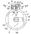
- FIG. 2 is a plan view of the main part of FIG. 3 is a cross-sectional view taken along line III-III in FIG.
- FIG. 4 is an exploded perspective view of the thermal sensor unit.
- the on-off valve side in FIG. 1 is the front, and the flow rate controller side is the rear.
- This top / bottom / front / rear is convenient, and the front / rear may be reversed or the top / bottom may be left / right.
- FIG. 1 shows a part of two lines (2) of an integrated fluid control device (1) composed of a plurality of lines.
- Each line (2) includes a flow controller (first fluid control device) (3) and an on-off valve (second fluid control device) that opens and closes the fluid passage (not shown) of the flow controller (3). ) (4), multiple fluid control devices (not shown) (other on-off valves, regulators, filters, etc.) and thermal sensor unit for managing the temperature of the fluid flowing through the fluid passage of the flow controller (3) (5).
- the flow controller (3) is called a mass flow controller and consists of a main body (11) with a built-in flow rate adjusting function and front and rear extension passage blocks (12) and (13) that support it.
- the overhang passage block (12) is provided with a leak port (12a) used in a leak test of the flow rate controller (3) so as to open upward.
- the on-off valve (4) is an air operated valve and is provided above the main body (14) and a rectangular parallelepiped block-shaped main body (14) in which a passage communicating with the fluid passage of the flow rate controller (3) is formed. And a casing (15) containing an actuator (opening / closing mechanism).
- the casing (15) has a top wall (15a), and a joint portion (16) for connecting a compressed air introduction pipe for introducing compressed air into the casing (15) is provided at the center of the top wall (15a). ) Is provided.
- the top wall (15a) has a shape in which both sides of the disc are cut off.
- the fluid passage of the flow controller (3) and the fluid passage of the on-off valve (4) are below these so as to span both the front overhang passage block (12) and the body (14) of the on-off valve (4).
- the passage block (6) is provided for communication.
- the front overhanging passage block (12) and the main body (14) of the on-off valve (4) are fixed to the passage block (6) by a hexagon socket bolt (7) from above.
- the thermal sensor unit (5) includes a cord-shaped thermal sensor (17) having a detection end (17a) at the tip, a flange (18) passed through the thermal sensor (17), and an on-off valve (4). And a support member (19) that supports the thermal sensor (17).
- the thermal sensor (17) is provided with a sheath thermocouple.
- the flange (18) has a rectangular plate shape, and is a screw through which the sensor insertion hole (18a) through which the thermal sensor (17) is inserted and the male screw for flange (20) to which the flange (18) is screwed are inserted.
- An insertion hole (18b) is provided.
- the support member (19) extends an annular main body (21) provided with a slit (22) at one place in the circumferential direction and a slit (22) provided in the main body (21) outward in the radial direction. And a pair of protrusions (a first protrusion (23) and a second protrusion (24)) provided integrally with the main body (21).
- the main body (21) has a short cylindrical surface on the outer peripheral surface (21a), and the inner peripheral surface (21b) has a shape corresponding to the outer peripheral surface of the top wall (15a) of the casing (15) (for example, both sides of the cylindrical surface are Flat surface). Since the main body (21) is provided with the slit (22), the main body (21) has elasticity in a direction in which the width of the slit (22) is widened or narrowed.
- the first protrusion (23) has a screw insertion hole (26) for inserting the supporting member male screw (25) from the surface opposite to the surface facing the second protrusion (24). Is provided.
- the second projecting portion (24) is provided with a female screw portion (27) to which the support member male screw (25) is screwed so as to extend in the same direction as the screw insertion hole (26).
- the second projecting portion (24) is further provided with a female screw portion (28) extending upward.
- the screw insertion hole (26) and the female thread portion (27) are perpendicular to the direction in which the slit (22) extends as viewed from above, but the horizontal plane (open / close
- the lower surface of the valve (4), the upper surface of the top wall (15a) of the casing (15), etc.) are provided so that the screw insertion hole (26) is on the upper side.
- the support member external thread (25) is a hexagon socket head cap screw and can be tightened using a tightening jig for the hexagon socket head cap screw.
- the inner peripheral surface (21b) of the annular main body (21) of the support member (19) has a shape that can be loosely fitted to the outer peripheral surface of the top wall (15a) of the casing (15).
- the male screw (25) By tightening the male screw (25), the width of the slit (22) is narrowed, whereby the support member (19) is fixed to the casing (15).
- the opposing surfaces of the pair of protrusions (23) and (24) are provided with semicircular recesses (29) and (30) extending in the vertical direction, respectively, and these two recesses ( 29)
- the thermal sensor (17) is inserted through the through hole portion formed by (30).
- the flange (18) with the thermal sensor (17) inserted into the sensor insertion hole (18a) is tightened with the flange male screw (20) with the support member (19) not attached to the on-off valve (4).
- the support member (19) to which the thermal sensor (17) is attached is fitted onto the casing (15) from above, and in this state, the detection end (17a) of the thermal sensor (17) is connected to the leak port (12a).
- the support member external thread (25) is tightened.
- the screw insertion hole (26) and the female thread part (27) are inclined, so that the work from above the top wall (15a) of the casing (15) can be performed.
- the support member (19) can be attached while avoiding interference with the top wall (15a) of the adjacent on-off valve (4) and the thermal sensor unit (5).
- the thermal sensor unit (5) is detachably attached to the on-off valve (4).
- the detection end (17a) of the thermal sensor (17) is preferable to arrange the detection end (17a) of the thermal sensor (17) as close as possible to the fluid.
- the leak port (12a) provided in the overhanging block (12) of the flow rate controller (3) the temperature can be accurately measured.
- the thermal sensor (17) When using the leak port (12a), the thermal sensor (17) is inserted using the hexagon socket bolt (7) that secures the overhanging passage block (12) on the front side to the passage block (6). It is also possible to fix the flange (18) to the front extension passage block (12), but in this case, it is necessary to remove the flow controller (3) when attaching or detaching the thermal sensor (17). The line was opened to the atmosphere, and there was a problem that it took much time to attach and detach the thermal sensor (17).
- the thermal sensor unit (5) can be attached and detached without affecting the function of the fluid control device (1). Moreover, because the thermal sensor unit (5) is fixed using the on-off valve (4), the space existing in the fluid control device (1) is effectively used, and the hose is spatially used. Even when it is difficult to attach the thermal sensor (17) using the band, the thermal sensor unit (5) can be installed.
- the mass flow controller is exemplified as the flow rate controller (3), but a fluid variable flow rate control device may be used as the flow rate controller (3).
- a fluid variable flow rate control device may be used as the flow rate controller (3).
- other two fluid control devices adjacent to each other can be used.
- the shape of the inner peripheral surface of the main body of the support member is appropriately changed according to the shape of the fluid control device to which the support member is attached.
- the outer peripheral surface shape of the main body of the support member may be a circumferential surface (cylindrical shape) as described above, or may be a rectangular tube shape.
- the thermal sensor can be easily installed in the fluid control device used in the semiconductor manufacturing apparatus or the like, the control accuracy of the fluid control device can be improved and its application can be expanded.
Landscapes
- Engineering & Computer Science (AREA)
- General Engineering & Computer Science (AREA)
- Physics & Mathematics (AREA)
- General Physics & Mathematics (AREA)
- Mechanical Engineering (AREA)
- Automation & Control Theory (AREA)
- Power Engineering (AREA)
- Valve Housings (AREA)
- Flow Control (AREA)
- Indication Of The Valve Opening Or Closing Status (AREA)
- Temperature-Responsive Valves (AREA)
Abstract
Priority Applications (5)
| Application Number | Priority Date | Filing Date | Title |
|---|---|---|---|
| JP2015504224A JP6240661B2 (ja) | 2013-03-08 | 2014-02-17 | 流体制御装置および流体制御装置へのサーマルセンサ設置構造 |
| SG11201507088YA SG11201507088YA (en) | 2013-03-08 | 2014-02-17 | Fluid control apparatus and thermal sensor installation structure with respect to fluid control apparatus |
| CN201480009481.0A CN105102868B (zh) | 2013-03-08 | 2014-02-17 | 流体控制装置以及流体控制装置上的热传感器设置结构 |
| US14/772,828 US9696727B2 (en) | 2013-03-08 | 2014-02-17 | Fluid control apparatus and thermal sensor installation structure with respect to fluid control apparatus |
| KR1020157022600A KR101775257B1 (ko) | 2013-03-08 | 2014-02-17 | 유체 제어 장치 및 유체 제어 장치에의 서멀 센서 설치 구조 |
Applications Claiming Priority (2)
| Application Number | Priority Date | Filing Date | Title |
|---|---|---|---|
| JP2013-046867 | 2013-03-08 | ||
| JP2013046867 | 2013-03-08 |
Publications (1)
| Publication Number | Publication Date |
|---|---|
| WO2014136557A1 true WO2014136557A1 (fr) | 2014-09-12 |
Family
ID=51491081
Family Applications (1)
| Application Number | Title | Priority Date | Filing Date |
|---|---|---|---|
| PCT/JP2014/053609 Ceased WO2014136557A1 (fr) | 2013-03-08 | 2014-02-17 | Dispositif de commande de fluide et structure pour monter un capteur thermique sur le dispositif de commande de fluide |
Country Status (7)
| Country | Link |
|---|---|
| US (1) | US9696727B2 (fr) |
| JP (1) | JP6240661B2 (fr) |
| KR (1) | KR101775257B1 (fr) |
| CN (1) | CN105102868B (fr) |
| SG (1) | SG11201507088YA (fr) |
| TW (1) | TWI611128B (fr) |
| WO (1) | WO2014136557A1 (fr) |
Cited By (6)
| Publication number | Priority date | Publication date | Assignee | Title |
|---|---|---|---|---|
| CN105466554A (zh) * | 2015-12-25 | 2016-04-06 | 中电投工程研究检测评定中心 | 竖向结构构件振动检测装置 |
| JP2016180483A (ja) * | 2015-03-25 | 2016-10-13 | 株式会社フジキン | 流体制御装置 |
| JP2016191404A (ja) * | 2015-03-31 | 2016-11-10 | 株式会社フジキン | センサ保持具および流体制御装置 |
| WO2018180886A1 (fr) * | 2017-03-30 | 2018-10-04 | 株式会社フジキン | Dispositif de régulation de fluide et élément de maintien de capteur |
| JP2022030609A (ja) * | 2020-08-07 | 2022-02-18 | 株式会社フジキン | センサ支持具およびそれを備える流体制御装置 |
| JP7488525B2 (ja) | 2020-10-28 | 2024-05-22 | 株式会社フジキン | センサ固定具及び流体制御装置 |
Families Citing this family (7)
| Publication number | Priority date | Publication date | Assignee | Title |
|---|---|---|---|---|
| DE102014012688B4 (de) * | 2014-09-01 | 2022-04-21 | Acs Air Compressor Systeme Gmbh | Mehrwegeventil |
| WO2018079288A1 (fr) * | 2016-10-24 | 2018-05-03 | 株式会社フジキン | Dispositif de commande de fluide et procédé de fabrication de produit utilisant le dispositif de commande de fluide |
| US11731153B2 (en) * | 2017-07-24 | 2023-08-22 | Carlisle Fluid Technologies, LLC | Systems and methods for communication and control in fluid delivery systems |
| CN113227623A (zh) * | 2018-12-27 | 2021-08-06 | 株式会社富士金 | 流体控制装置、接头块和流体控制装置的制造方法 |
| WO2020196353A1 (fr) * | 2019-03-25 | 2020-10-01 | 株式会社フジキン | Structure de fixation pour capteur de température |
| EP3795971A1 (fr) * | 2019-09-17 | 2021-03-24 | TE Connectivity India Private Limited | Détecteur de fuite de fluide et procédé de détection de fuite de fluide basé sur des mesures de transfert de chaleur |
| JP7356141B2 (ja) * | 2019-12-27 | 2023-10-04 | 株式会社フジキン | 固定ユニットおよび流体制御装置 |
Citations (4)
| Publication number | Priority date | Publication date | Assignee | Title |
|---|---|---|---|---|
| JPH0774113A (ja) * | 1993-09-02 | 1995-03-17 | Ckd Corp | ガス供給装置 |
| JP2002250645A (ja) * | 2001-02-26 | 2002-09-06 | Stec Inc | 集積タイプのマスフローコントローラを用いた流体供給機構 |
| JP2006083959A (ja) * | 2004-09-16 | 2006-03-30 | Fujikin Inc | センサ付き継手部材 |
| JP2006519339A (ja) * | 2003-03-03 | 2006-08-24 | レッドウッド マイクロシステムズ インコーポレイテッド | 流体送出システム及びこのシステム用の取り付けパネル |
Family Cites Families (33)
| Publication number | Priority date | Publication date | Assignee | Title |
|---|---|---|---|---|
| US3857282A (en) * | 1973-04-30 | 1974-12-31 | Trace Inc | Portable tester for hydraulic power circuits |
| US4016758A (en) * | 1975-09-09 | 1977-04-12 | Taylor Julian S | Thermal gauge probe |
| JPS60102639U (ja) | 1983-12-20 | 1985-07-12 | 三菱重工業株式会社 | 温度測定装置 |
| US5230366A (en) * | 1992-07-09 | 1993-07-27 | Griswold Controls | Automatic fluid flow control device |
| US6044701A (en) * | 1992-10-16 | 2000-04-04 | Unit Instruments, Inc. | Thermal mass flow controller having orthogonal thermal mass flow sensor |
| JP3605705B2 (ja) * | 1995-07-19 | 2004-12-22 | 株式会社フジキン | 流体制御器 |
| US6019114A (en) * | 1997-02-12 | 2000-02-01 | Icon Dynaamics, Llc | Self-metering reservoir |
| JP3292817B2 (ja) * | 1997-04-24 | 2002-06-17 | 三菱電機株式会社 | 感熱式流量センサ |
| DE29717492U1 (de) * | 1997-09-30 | 1997-11-27 | Festo AG & Co, 73734 Esslingen | Befestigungsvorrichtung zur Befestigung eines Sensors |
| JP4378553B2 (ja) * | 1997-10-13 | 2009-12-09 | 忠弘 大見 | 流体制御装置 |
| WO2000031462A1 (fr) | 1998-11-20 | 2000-06-02 | Mykrolis Corporation | Systeme et procede d'integration de composants gazeux |
| US6363958B1 (en) * | 1999-05-10 | 2002-04-02 | Parker-Hannifin Corporation | Flow control of process gas in semiconductor manufacturing |
| US6308553B1 (en) * | 1999-06-04 | 2001-10-30 | Honeywell International Inc | Self-normalizing flow sensor and method for the same |
| KR100323239B1 (ko) | 1999-09-08 | 2002-02-19 | 최성봉 | 경사체결구조를 갖는 삼방향밸브 |
| JP2001201414A (ja) * | 2000-01-20 | 2001-07-27 | Smc Corp | 複合センサ及び複合センサを備えたフローコントローラ |
| ITPN20010003U1 (it) * | 2001-01-25 | 2002-07-25 | Sipa Spa | Dispositivo per il rilevamento di variazioni di temperatura con alloggiamento per il sensore |
| US6490229B1 (en) * | 2001-11-09 | 2002-12-03 | John T. Caver | Trolling motor transducer mount |
| CA2416275A1 (fr) * | 2003-01-08 | 2004-07-08 | Hydro Quebec | Motorisation d'un bracelet de mesure d'epaisseur d'un tuyau |
| US6843139B2 (en) * | 2003-03-12 | 2005-01-18 | Rosemount Inc. | Flow instrument with multisensors |
| JP2004340199A (ja) * | 2003-05-14 | 2004-12-02 | Fujikin Inc | 加熱装置付き流体制御装置 |
| NL1025631C2 (nl) * | 2004-03-03 | 2005-09-08 | Berkin Bv | Afdichtingsamenstel. |
| JP4753173B2 (ja) | 2005-06-17 | 2011-08-24 | 株式会社フジキン | 流体制御装置 |
| US7296465B2 (en) * | 2005-11-22 | 2007-11-20 | Mks Instruments, Inc. | Vertical mount mass flow sensor |
| US8079383B2 (en) * | 2006-12-07 | 2011-12-20 | Mks Instruments, Inc. | Controller gain scheduling for mass flow controllers |
| US7552643B2 (en) * | 2006-12-08 | 2009-06-30 | Centre For Nuclear Energy Research (CNER) | Device and system for corrosion detection |
| JP5150628B2 (ja) * | 2007-05-31 | 2013-02-20 | 東京エレクトロン株式会社 | 流体制御装置 |
| US20080302426A1 (en) * | 2007-06-06 | 2008-12-11 | Greg Patrick Mulligan | System and method of securing removable components for distribution of fluids |
| DE102007042789A1 (de) * | 2007-09-07 | 2009-03-12 | Robert Bosch Gmbh | Steckfühler zur Messung mindestens einer Eigenschaft eines fluiden Mediums |
| DE102010043865A1 (de) * | 2009-11-30 | 2011-07-14 | Horiba Stec Co., Ltd. | Fluid device |
| DE102010015813A1 (de) * | 2010-04-20 | 2011-10-20 | Krohne Messtechnik Gmbh | Sensoranordnung für ein kalorimetrisches Massedurchflussmessgerät |
| JP5674521B2 (ja) * | 2011-03-25 | 2015-02-25 | 株式会社東芝 | 蒸気弁装置および蒸気タービンプラント |
| US9188989B1 (en) * | 2011-08-20 | 2015-11-17 | Daniel T. Mudd | Flow node to deliver process gas using a remote pressure measurement device |
| US9335768B2 (en) * | 2013-09-12 | 2016-05-10 | Lam Research Corporation | Cluster mass flow devices and multi-line mass flow devices incorporating the same |
-
2014
- 2014-02-17 WO PCT/JP2014/053609 patent/WO2014136557A1/fr not_active Ceased
- 2014-02-17 CN CN201480009481.0A patent/CN105102868B/zh not_active Expired - Fee Related
- 2014-02-17 US US14/772,828 patent/US9696727B2/en active Active
- 2014-02-17 JP JP2015504224A patent/JP6240661B2/ja active Active
- 2014-02-17 KR KR1020157022600A patent/KR101775257B1/ko active Active
- 2014-02-17 SG SG11201507088YA patent/SG11201507088YA/en unknown
- 2014-03-06 TW TW103107621A patent/TWI611128B/zh active
Patent Citations (4)
| Publication number | Priority date | Publication date | Assignee | Title |
|---|---|---|---|---|
| JPH0774113A (ja) * | 1993-09-02 | 1995-03-17 | Ckd Corp | ガス供給装置 |
| JP2002250645A (ja) * | 2001-02-26 | 2002-09-06 | Stec Inc | 集積タイプのマスフローコントローラを用いた流体供給機構 |
| JP2006519339A (ja) * | 2003-03-03 | 2006-08-24 | レッドウッド マイクロシステムズ インコーポレイテッド | 流体送出システム及びこのシステム用の取り付けパネル |
| JP2006083959A (ja) * | 2004-09-16 | 2006-03-30 | Fujikin Inc | センサ付き継手部材 |
Cited By (8)
| Publication number | Priority date | Publication date | Assignee | Title |
|---|---|---|---|---|
| JP2016180483A (ja) * | 2015-03-25 | 2016-10-13 | 株式会社フジキン | 流体制御装置 |
| JP2016191404A (ja) * | 2015-03-31 | 2016-11-10 | 株式会社フジキン | センサ保持具および流体制御装置 |
| CN105466554A (zh) * | 2015-12-25 | 2016-04-06 | 中电投工程研究检测评定中心 | 竖向结构构件振动检测装置 |
| WO2018180886A1 (fr) * | 2017-03-30 | 2018-10-04 | 株式会社フジキン | Dispositif de régulation de fluide et élément de maintien de capteur |
| TWI676755B (zh) * | 2017-03-30 | 2019-11-11 | 日商富士金股份有限公司 | 流體控制機器、流體控制裝置及感測器固持構件 |
| JP2022030609A (ja) * | 2020-08-07 | 2022-02-18 | 株式会社フジキン | センサ支持具およびそれを備える流体制御装置 |
| JP7530629B2 (ja) | 2020-08-07 | 2024-08-08 | 株式会社フジキン | センサ支持具およびそれを備える流体制御装置 |
| JP7488525B2 (ja) | 2020-10-28 | 2024-05-22 | 株式会社フジキン | センサ固定具及び流体制御装置 |
Also Published As
| Publication number | Publication date |
|---|---|
| KR101775257B1 (ko) | 2017-09-05 |
| CN105102868A (zh) | 2015-11-25 |
| CN105102868B (zh) | 2017-05-24 |
| US20160018827A1 (en) | 2016-01-21 |
| US9696727B2 (en) | 2017-07-04 |
| SG11201507088YA (en) | 2015-10-29 |
| KR20150107879A (ko) | 2015-09-23 |
| JPWO2014136557A1 (ja) | 2017-02-09 |
| JP6240661B2 (ja) | 2017-11-29 |
| TW201443359A (zh) | 2014-11-16 |
| TWI611128B (zh) | 2018-01-11 |
Similar Documents
| Publication | Publication Date | Title |
|---|---|---|
| JP6240661B2 (ja) | 流体制御装置および流体制御装置へのサーマルセンサ設置構造 | |
| EP3143850B1 (fr) | Collecteur de fluide | |
| JP5127304B2 (ja) | 流体制御装置 | |
| CA2871678C (fr) | Transmetteur d'ecoulement de fluide de traitement a bride de fluide de traitement coplanaire a ailettes | |
| US10895484B2 (en) | Gas supply device capable of measuring flow rate, flowmeter, and flow rate measuring method | |
| KR102236672B1 (ko) | 보일러 튜브 모사장치 | |
| US20150337985A1 (en) | Fluid control apparatus | |
| CN204373798U (zh) | 卡箍式表面温度传感器 | |
| KR20160018740A (ko) | 유동성 파라미터를 측정하는, 덕트를 구비한 장치 및 그 설비 | |
| CN103727521A (zh) | 一种温度测量元件固定装置及锅炉 | |
| TW201839305A (zh) | 轉換接頭、具有此轉換接頭的整合型流體供給裝置以及流體零件的安裝方法 | |
| CN112697420A (zh) | 检测工装 | |
| JP6175300B2 (ja) | 流体制御装置用継手部材および流体制御装置 | |
| JP2008292484A (ja) | 集積タイプのマスフローコントローラを用いた流体供給機構 | |
| JP6484497B2 (ja) | 断熱カバーおよび流体制御装置 | |
| RU2017103677A (ru) | Устройство для готовки | |
| EP3043113A1 (fr) | Dispositif de fixation pour carreau thermo-isolant de chambre de combustion de turbine à gaz | |
| JP6226792B2 (ja) | 開閉弁及びガスメータ | |
| IT201800008109A1 (it) | Gruppo termostato perfezionato | |
| CN214149818U (zh) | 检测工装 | |
| TWI579535B (zh) | Gas flow meter | |
| JP2020067757A (ja) | 流量制御装置、流体制御装置、およびデータ取得方法 | |
| JP2017180610A (ja) | センサ保持具およびそれを備えた流体制御装置 | |
| KR20110137586A (ko) | 전기공압식 통합 제어 패널 | |
| JP2022030609A (ja) | センサ支持具およびそれを備える流体制御装置 |
Legal Events
| Date | Code | Title | Description |
|---|---|---|---|
| WWE | Wipo information: entry into national phase |
Ref document number: 201480009481.0 Country of ref document: CN |
|
| 121 | Ep: the epo has been informed by wipo that ep was designated in this application |
Ref document number: 14759846 Country of ref document: EP Kind code of ref document: A1 |
|
| ENP | Entry into the national phase |
Ref document number: 20157022600 Country of ref document: KR Kind code of ref document: A |
|
| ENP | Entry into the national phase |
Ref document number: 2015504224 Country of ref document: JP Kind code of ref document: A |
|
| WWE | Wipo information: entry into national phase |
Ref document number: 14772828 Country of ref document: US |
|
| NENP | Non-entry into the national phase |
Ref country code: DE |
|
| 122 | Ep: pct application non-entry in european phase |
Ref document number: 14759846 Country of ref document: EP Kind code of ref document: A1 |