WO2014136759A1 - 注射器および注射器用ガスケット - Google Patents
注射器および注射器用ガスケット Download PDFInfo
- Publication number
- WO2014136759A1 WO2014136759A1 PCT/JP2014/055430 JP2014055430W WO2014136759A1 WO 2014136759 A1 WO2014136759 A1 WO 2014136759A1 JP 2014055430 W JP2014055430 W JP 2014055430W WO 2014136759 A1 WO2014136759 A1 WO 2014136759A1
- Authority
- WO
- WIPO (PCT)
- Prior art keywords
- gasket
- syringe
- peripheral surface
- barrel
- core
- Prior art date
- Legal status (The legal status is an assumption and is not a legal conclusion. Google has not performed a legal analysis and makes no representation as to the accuracy of the status listed.)
- Ceased
Links
Images

Classifications
-
- A—HUMAN NECESSITIES
- A61—MEDICAL OR VETERINARY SCIENCE; HYGIENE
- A61M—DEVICES FOR INTRODUCING MEDIA INTO, OR ONTO, THE BODY; DEVICES FOR TRANSDUCING BODY MEDIA OR FOR TAKING MEDIA FROM THE BODY; DEVICES FOR PRODUCING OR ENDING SLEEP OR STUPOR
- A61M5/00—Devices for bringing media into the body in a subcutaneous, intra-vascular or intramuscular way; Accessories therefor, e.g. filling or cleaning devices, arm-rests
- A61M5/178—Syringes
- A61M5/31—Details
- A61M5/315—Pistons; Piston-rods; Guiding, blocking or restricting the movement of the rod or piston; Appliances on the rod for facilitating dosing ; Dosing mechanisms
- A61M5/31511—Piston or piston-rod constructions, e.g. connection of piston with piston-rod
- A61M5/31513—Piston constructions to improve sealing or sliding
-
- A—HUMAN NECESSITIES
- A61—MEDICAL OR VETERINARY SCIENCE; HYGIENE
- A61M—DEVICES FOR INTRODUCING MEDIA INTO, OR ONTO, THE BODY; DEVICES FOR TRANSDUCING BODY MEDIA OR FOR TAKING MEDIA FROM THE BODY; DEVICES FOR PRODUCING OR ENDING SLEEP OR STUPOR
- A61M5/00—Devices for bringing media into the body in a subcutaneous, intra-vascular or intramuscular way; Accessories therefor, e.g. filling or cleaning devices, arm-rests
- A61M5/178—Syringes
- A61M5/31—Details
- A61M5/315—Pistons; Piston-rods; Guiding, blocking or restricting the movement of the rod or piston; Appliances on the rod for facilitating dosing ; Dosing mechanisms
- A61M5/31511—Piston or piston-rod constructions, e.g. connection of piston with piston-rod
- A61M5/31515—Connection of piston with piston rod
-
- A—HUMAN NECESSITIES
- A61—MEDICAL OR VETERINARY SCIENCE; HYGIENE
- A61M—DEVICES FOR INTRODUCING MEDIA INTO, OR ONTO, THE BODY; DEVICES FOR TRANSDUCING BODY MEDIA OR FOR TAKING MEDIA FROM THE BODY; DEVICES FOR PRODUCING OR ENDING SLEEP OR STUPOR
- A61M5/00—Devices for bringing media into the body in a subcutaneous, intra-vascular or intramuscular way; Accessories therefor, e.g. filling or cleaning devices, arm-rests
- A61M5/178—Syringes
- A61M5/31—Details
- A61M5/3129—Syringe barrels
- A61M2005/3131—Syringe barrels specially adapted for improving sealing or sliding
Definitions
- the present invention relates to a gasket for a syringe attached to an end of a plunger rod of a syringe so as to be slidable in a barrel of the syringe, and a syringe provided with the same.
- the syringe gasket (hereinafter sometimes simply referred to as a gasket) is composed mainly of a rubber material such as natural rubber, isoprene rubber, styrene / butadiene rubber, butadiene rubber, or a styrene-butadiene copolymer. It is general that the main component is an elastomer material as represented.
- a rubber gasket When a rubber gasket is used as a syringe gasket, it usually performs better in terms of liquid-tightness than an elastomer gasket, but a part of the drug solution has the property of adsorbing to rubber. Since some of them contain components, elastomers are preferably used when using such chemical solutions.
- Patent Document 1 Japanese Patent Application Laid-Open No. 2001-190667
- Patent Document 2 Japanese Patent Application Laid-Open No. 2008-307237
- the present invention has been made in view of such problems, and an object thereof is to provide a syringe gasket that is excellent in liquid tightness and can be prevented from falling off the plunger rod, and a syringe including the same. To do.
- the syringe according to the present invention includes a barrel, a gasket slidably arranged in the barrel, and a plunger rod to which the gasket is attached.
- the end of the plunger rod on the gasket side is provided with a coupler having an external thread formed on the outer peripheral surface, and the end of the gasket on the plunger rod side is provided with a female on the inner peripheral surface.
- a recess having a threaded portion is provided.
- the gasket is attached to the coupler by screwing the male screw portion into the female screw portion.
- the gasket defines an inner peripheral surface of the recess and a spiral core member that defines the female screw portion provided on the inner peripheral surface, and a sliding surface that contacts the inner peripheral surface of the barrel.
- a packing portion that exhibits flexibility to cover the outer peripheral surface of the core member portion.
- the core material part is harder than the packing part.
- the core part is preferably made of plastic, and in that case, the packing part is preferably made of elastomer or rubber.
- the gasket is constituted by an integrally molded part in which the packing portion is fixed to the core material portion.
- the core part and the packing part are preferably formed by two-color molding.
- a drug solution may be filled in a space defined by the barrel and the gasket.
- a gasket for a syringe according to the present invention has a recess for being attached to a coupler provided at an end of a plunger rod of a syringe so as to be slidable within a barrel of the syringe, and is flexible. And a core part harder than the packing part.
- a female screw portion that can be screwed into a male screw portion provided on the outer peripheral surface of the coupler is provided on the inner peripheral surface of the recess.
- the core member has a spiral shape that defines an inner peripheral surface of the recess and the female screw portion provided on the inner peripheral surface.
- the packing portion defines a sliding surface that comes into contact with the inner peripheral surface of the barrel and covers the outer peripheral surface of the core member portion.
- a syringe gasket that is excellent in liquid tightness and can be prevented from falling off from the plunger rod, and a syringe including the same.
- FIG. 1 is a cross-sectional view of a syringe according to an embodiment of the present invention.
- the syringe 1 and the gasket 4 for syringes in this Embodiment are demonstrated.
- the syringe 1 in this Embodiment is what is called a prefilled syringe with which the chemical
- the syringe 1 includes a barrel 2, a plunger rod 3, a gasket 4, a cap 5, and a drug solution 6.
- the chemical solution 6 is filled in the barrel 2 and is held in a liquid-tight manner from the outside space by the barrel 2, the gasket 4, and the cap 5.
- the barrel 2 is made of a substantially cylindrical member with a bottom that is open at the base end 21 side, which is one end in the axial direction, and is generally closed at the tip end 22 side, which is the other end in the axial direction. Composed.
- a flange portion 211 for holding the barrel 2 at the time of injection is provided on the base end 21 side of the barrel 2.
- a needle attachment portion 221 to which an injection needle is attached is provided at the tip 22 corresponding to the bottom portion of the barrel 2.
- the tip of the needle attachment portion 221 is open, and the space inside the barrel 2 communicates with the space outside the barrel 2 via the needle attachment portion 221.
- a cap 5 is attached to the needle attachment portion 221, whereby the drug solution 6 filled in the barrel 2 is liquid-tightly held from the external space on the distal end 22 side of the syringe 1 by the cap 5.
- the gasket 4 is made of a substantially cylindrical member, and is inserted into the space in the barrel 2.
- the gasket 4 is slidably disposed in the barrel 2, and a part of the outer peripheral surface thereof is in pressure contact with the inner peripheral surface of the barrel 2 as a sliding surface.
- the axial end of the gasket 4 located on the tip 22 side of the barrel 2 is in contact with the chemical solution 6 filled in the barrel 2. Thereby, the chemical
- a recess 43 for attaching the gasket 4 to a coupler 31 of the plunger rod 3 described later is provided at the axial end of the gasket 4 positioned on the base end 21 side of the barrel 2.
- a female screw portion 413 is formed on the inner peripheral surface of the recess 43. Details of the gasket 4 will be described later.
- the plunger rod 3 is made of a substantially cylindrical member, and is made of, for example, a resin injection molded product. One end portion of the plunger rod 3 in the axial direction is inserted into the barrel 2 from the base end 21 side of the barrel 2, and the other end portion of the plunger rod 3 in the axial direction faces the outside of the barrel 2. Stick out.
- the one end of the plunger rod 3 is provided with a substantially cylindrical coupler 31 that protrudes toward the tip 22 side of the barrel 2.
- a male screw portion 313 is formed on the outer peripheral surface of the coupler 31.
- the coupler 31 is inserted into the recess 43 of the gasket 4.
- the gasket 4 is attached to the coupler 31 by the male screw portion 313 formed on the outer peripheral surface of the coupler 31 being screwed to the female screw portion 413 formed on the inner peripheral surface of the recess 43. ing. Thereby, the gasket 4 is fixed to the one end portion of the plunger rod 3.
- the injection needle is attached to the needle attachment portion 221 of the barrel 2 so as to pierce the cap 5, and then the plunger rod 3 is directed toward the tip 22 side of the barrel 2 (in the direction of arrow A shown in the figure).
- the plunger rod 3 is directed toward the tip 22 side of the barrel 2 (in the direction of arrow A shown in the figure).
- the gasket 4 slides in the barrel 2 toward the tip 22 side while maintaining liquid tightness, and the chemical liquid 6 is brought into contact with the needle mounting portion 221 by the applied pressure accompanying the sliding of the gasket 4.
- the injection needle is attached to the needle attachment portion 221 of the barrel 2 so as to pierce the cap 5, and then the plunger rod 3 is directed toward the tip 22 side of the barrel 2 (in the direction of arrow A shown in the figure).
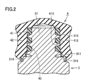
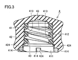
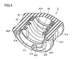
- FIG. 2 is an enlarged cross-sectional view of the main part of the syringe shown in FIG. 1, and FIGS. 3 and 4 are a cross-sectional view and a partially broken perspective view of the gasket for the syringe shown in FIG. 1, respectively.
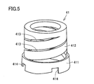
- FIG. 5 is a perspective view of the core part of the syringe gasket shown in FIG.
- FIGS. 2 to 5 a more detailed structure of the syringe gasket 4 in the present embodiment and an assembly structure of the syringe gasket 4 in the syringe 1 in the present embodiment with respect to the plunger rod 3 are described. Will be described.
- the gasket 4 includes a core part 41 and a packing part 42.
- the concave portion 43 described above is defined by the core portion 41 and the packing portion 42.
- the core portion 41 defines the inner peripheral surface of the concave portion 43 and the packing portion 42 defines the bottom surface of the concave portion 43. .
- the core part 41 mainly constitutes a part fixed to the plunger rod 3 of the gasket 4.
- the packing part 42 mainly constitutes a part for liquid-tightly sealing the chemical 6 of the gasket 4 in the barrel 2. For this reason, the outer side of the core part 41 is covered with the packing part 42.
- the core material portion 41 is made of a harder member than the packing portion 42.
- the core material portion 41 for example, a plastic material mainly composed of polypropylene resin or polyethylene resin can be used.
- the core member 41 is preferably made of polypropylene resin.
- the packing part 42 is made of a member exhibiting flexibility as compared with the core part 41.
- the packing portion 42 is made of, for example, a rubber mainly composed of natural rubber, isoprene rubber, styrene / butadiene rubber, butadiene rubber, or a thermoplastic elastomer represented by a styrene-butadiene copolymer.
- the thing made from the elastomer which has a main component can be utilized.
- medical solution 6 contains the component which has the property to adsorb
- the gasket 4 is preferably composed of an integrally molded product in which a packing part 42 is fixed to a core part 41.
- a specific manufacturing method an insert molding method or a two-color molding method as a molding welding technique using a mold can be used.
- the core part 41 is formed in advance using a plastic material by injection molding using a mold, and the formed core part 41 is once completely released from the mold and taken out.
- the core part 41 is set as an insert part in another mold, and a molten rubber material or an elastomer material is poured into a mold cavity surrounding the set core part 41 to cure the packing part. 42 is formed, whereby the gasket 4 is obtained.
- the core part 41 is formed in advance using a plastic material by injection molding using a mold, and becomes a joint surface with the packing part 42 of the formed core part 41.
- a part of the mold is separated so that only the part is exposed, and another mold is set so as to cover the part to be the joint surface in place of the separated mold, and the mold surrounding the core part 41
- a molten rubber material or elastomer material is poured into the mold cavity and cured to form the packing portion 42, thereby obtaining the gasket 4.
- the gasket 4 is configured as an integrally molded product by using these methods, the core part 41 and the packing part 42 are firmly fixed at the joining surface, and are handled as one independent part. It becomes possible. In view of productivity, it is more preferable to use a two-color molding method.
- the core member 41 has a spiral shape, and has a substantially cylindrical outer shape as a whole including the collar 411 and the spiral portion 412.
- the collar 411 is located at the end of the gasket 4 on the plunger rod 3 side
- the spiral portion 412 is an end located on the opposite side of the end of the gasket 4 from the plunger rod 3 side. It extends towards the club side.
- the packing part 42 has a bottomed substantially cylindrical outer shape as a whole.
- the cylindrical portion of the packing portion 42 covers the outer peripheral surface of the core member portion 41 (that is, the outer peripheral surface of the collar 411 and the outer peripheral surface of the spiral portion 412) and has a sliding surface that contacts the inner peripheral surface of the barrel 2.
- the outer peripheral surface of the gasket 4 is defined.
- the bottom portion of the packing portion 42 covers an end portion of the core portion 41 that is located on the side opposite to the end portion on the plunger rod 3 side.
- a spirally extending slit is formed in the spiral portion 412 of the core member portion 41, and a female screw portion 413 is defined by the slit.
- the female screw portion 413 is a portion that is screwed into the male screw portion 313 formed on the outer peripheral surface of the coupler 31 of the plunger rod 3 described above, and is located on the inner peripheral surface of the recess 43.
- the collar 411 of the core part 41 is provided with a plurality of notch-shaped locking hole portions 414 along the circumferential direction, and the packing portion 42 corresponding to the locking hole portion 414 includes A locking groove 424 is provided.
- the locking hole portion 414 and the locking groove portion 424 are portions for locking a protrusion 314 (see FIG. 2) formed at the base portion of the coupler 31 of the plunger rod 3, and the coupler 31 is screwed to the gasket 4. In the joined state, the rotation is stopped so that the screwing is not released.
- the gasket 4 is configured by the packing portion 42 exhibiting flexibility and the core material portion 41 that is harder than the packing portion 42.
- Both the inner peripheral surface of the recess 43 to be attached to the coupler 31 of the plunger rod 3 and the female screw portion 413 provided on the inner peripheral surface are defined by the core portion 41 having a spiral shape.
- a sliding surface that contacts the inner peripheral surface of the core member 41 is defined by a packing portion 42 that covers the outer peripheral surface of the core member 41.
- the repulsive force of the packing portion 4 can be increased by the amount of the hard core portion 41 located inside the packing portion 42, and the packing portion Even when a relatively flexible material is used as 42, the restoring force is increased and the time until the restoration is shortened, so that high liquid tightness can be secured.
- the core part 41 is hard, the plunger rod 43 and the gasket 4 can be screwed more firmly, and the fixing strength can be greatly increased.
- the syringe 1 and the syringe gasket 4 in the present embodiment it is possible to provide a syringe gasket that is excellent in liquid tightness and can be prevented from falling off the plunger rod 3, and a syringe equipped therewith.
- the gasket 4 is inserted into the barrel 2 by a so-called sleeve capping method.
- This sleeve stopper is inserted in a sleeve-shaped jig in a compressed state in advance, and the sleeve-shaped jig is inserted into a barrel and the gasket is brought into contact with a chemical solution using a rod or the like.
- This is a technique in which the gasket is left in the barrel by pushing it into the position and then pulling out only the sleeve-shaped jig.
- the gasket When assembling a syringe using this sleeve stopper, the gasket is compressed more than the thickness of the sleeve-shaped jig when the sleeve is stoppered. In some cases, the compressive force may cause the hard part to be deformed or crushed.
- the core part 41 that is a hard part has a spiral shape, that is, a coil spring shape, and therefore the core part 41 exhibits spring elasticity. Therefore, the tolerance for the deformation and breakage is increased as compared with the case where the core part 41 is formed of a cylindrical member.
- syringe 1 and the syringe gasket 4 in the present embodiment it is possible to prevent the core member 41 from being deformed or damaged even when the sleeve is plugged during assembly.
- Syringes can be manufactured with good yield.
- gasket configured by an integrally molded product in which the core material portion and the packing portion are integrally molded is exemplified.
- a gasket may be configured by combining the above.
- the gasket and the plunger rod are provided with the rotation retaining mechanism as an example, but the configuration is not essential.
- the core material portion has been described with an example in which the end located on the side opposite to the plunger rod side is opened.
- the end may be closed.
- a so-called prefilled syringe has been described as an example of a syringe to which the present invention is applied and a gasket for the syringe, but the application of the present invention is limited to this.
- the present invention can naturally also be applied to a syringe not pre-filled with a medicine and a syringe gasket provided in the syringe.
Landscapes
- Health & Medical Sciences (AREA)
- Vascular Medicine (AREA)
- Engineering & Computer Science (AREA)
- Anesthesiology (AREA)
- Biomedical Technology (AREA)
- Heart & Thoracic Surgery (AREA)
- Hematology (AREA)
- Life Sciences & Earth Sciences (AREA)
- Animal Behavior & Ethology (AREA)
- General Health & Medical Sciences (AREA)
- Public Health (AREA)
- Veterinary Medicine (AREA)
- Infusion, Injection, And Reservoir Apparatuses (AREA)
Abstract
Description
Claims (6)
- バレルと、
前記バレル内において摺動可能に配置されたガスケットと、
前記ガスケットが取付けられたプランジャーロッドとを備え、
前記プランジャーロッドの前記ガスケット側の端部には、外周面に雄ネジ部が形成されたカプラーが設けられ、
前記ガスケットの前記プランジャーロッド側の端部には、内周面に雌ネジ部が形成された凹部が設けられ、
前記ガスケットは、前記雌ネジ部に前記雄ネジ部が螺合されることで前記カプラーに取付けられ、
前記ガスケットは、前記凹部の内周面および当該内周面に設けられた前記雌ネジ部を規定する螺旋状の芯材部と、前記バレルの内周面に接触する摺動面を規定するとともに前記芯材部の外周面を覆う柔軟性を呈するパッキン部とを含み、
前記芯材部は、前記パッキン部よりも硬質である、注射器。 - 前記芯材部が、プラスチック製であり、
前記パッキン部が、エラストマー製またはゴム製である、請求項1に記載の注射器。 - 前記ガスケットが、前記芯材部に前記パッキン部が固着してなる一体成形品にて構成されている、請求項1または2に記載の注射器。
- 前記芯材部および前記パッキン部が、二色成形によって形成されている、請求項3に記載の注射器。
- 前記バレルと前記ガスケットとによって規定される空間内に薬液が充填されている、請求項1から4のいずれかに記載の注射器。
- 注射器のバレル内において摺動可能となるように、注射器のプランジャーロッドの端部に設けられたカプラーに取付けられるための凹部を有する注射器用ガスケットであって、
柔軟性を呈するパッキン部と、
前記パッキン部よりも硬質の芯材部とを備え、
前記凹部の内周面には、カプラーの外周面に設けられた雄ネジ部に螺合可能な雌ネジ部が設けられ、
前記芯材部は、前記凹部の内周面および当該内周面に設けられた前記雌ネジ部を規定する螺旋状の形状を有し、
前記パッキン部は、バレルの内周面に接触する摺動面を規定するとともに前記芯材部の外周面を覆っている、注射器用ガスケット。
Priority Applications (3)
| Application Number | Priority Date | Filing Date | Title |
|---|---|---|---|
| EP14760291.6A EP2965773A4 (en) | 2013-03-08 | 2014-03-04 | SYRINGE AND SPRAY SEAL |
| US14/772,245 US9827377B2 (en) | 2013-03-08 | 2014-03-04 | Syringe and syringe gasket |
| JP2015504323A JP6330800B2 (ja) | 2013-03-08 | 2014-03-04 | 注射器および注射器用ガスケット |
Applications Claiming Priority (2)
| Application Number | Priority Date | Filing Date | Title |
|---|---|---|---|
| JP2013-046883 | 2013-03-08 | ||
| JP2013046883 | 2013-03-08 |
Publications (1)
| Publication Number | Publication Date |
|---|---|
| WO2014136759A1 true WO2014136759A1 (ja) | 2014-09-12 |
Family
ID=51491275
Family Applications (1)
| Application Number | Title | Priority Date | Filing Date |
|---|---|---|---|
| PCT/JP2014/055430 Ceased WO2014136759A1 (ja) | 2013-03-08 | 2014-03-04 | 注射器および注射器用ガスケット |
Country Status (4)
| Country | Link |
|---|---|
| US (1) | US9827377B2 (ja) |
| EP (1) | EP2965773A4 (ja) |
| JP (1) | JP6330800B2 (ja) |
| WO (1) | WO2014136759A1 (ja) |
Families Citing this family (7)
| Publication number | Priority date | Publication date | Assignee | Title |
|---|---|---|---|---|
| WO2015130739A1 (en) * | 2014-02-26 | 2015-09-03 | 3M Innovative Properties Company | Device for dispensing a material |
| CN107635527B (zh) | 2015-03-10 | 2021-04-23 | 里珍纳龙药品有限公司 | 无菌刺穿系统和方法 |
| US10039886B2 (en) * | 2015-05-15 | 2018-08-07 | Black Tie Medical Inc. | Sealing assembly for a syringe barrel |
| US10369292B2 (en) * | 2016-01-15 | 2019-08-06 | W. L. Gore & Associates, Inc. | Syringe plunger assemblies |
| KR102540409B1 (ko) | 2017-05-05 | 2023-06-09 | 리제너론 파아마슈티컬스, 인크. | 자동 주사기 |
| JP7583053B2 (ja) * | 2020-02-13 | 2024-11-13 | ウエスト ファーマスーティカル サービシーズ インコーポレイテッド | 極低温貯蔵用の格納・搬送システム |
| USD1007676S1 (en) | 2021-11-16 | 2023-12-12 | Regeneron Pharmaceuticals, Inc. | Wearable autoinjector |
Citations (6)
| Publication number | Priority date | Publication date | Assignee | Title |
|---|---|---|---|---|
| JP2001137338A (ja) * | 1999-11-15 | 2001-05-22 | Kooki Engineering:Kk | シリンジ用ピストンの摺動部材及びその製造方法 |
| JP2001190667A (ja) | 2000-01-11 | 2001-07-17 | Nipro Corp | 注射器用ガスケットおよびその製造方法 |
| JP2002210010A (ja) * | 2000-11-14 | 2002-07-30 | Daikyo Seiko Ltd | 注射筒用ピストン |
| JP2003235974A (ja) * | 2002-02-18 | 2003-08-26 | Nemoto Kyorindo:Kk | ピストンヘッドおよびシリンジ |
| JP2008307237A (ja) | 2007-06-15 | 2008-12-25 | Nipro Corp | プレフィルドシリンジ |
| JP2010246842A (ja) * | 2009-04-20 | 2010-11-04 | Usui Seisakusho:Kk | シリンジ |
Family Cites Families (9)
| Publication number | Priority date | Publication date | Assignee | Title |
|---|---|---|---|---|
| US1799463A (en) | 1926-03-19 | 1931-04-07 | George N Hein | Hypodermic syringe |
| DE4438360C2 (de) * | 1994-10-27 | 1999-05-20 | Schott Glas | Vorfüllbare partikelarme, sterile Einmalspritze für die Injektion von Präparaten und Verfahren zu ihrer Herstellung |
| JP2000152989A (ja) * | 1998-11-19 | 2000-06-06 | Bracco Internatl Bv | 注入器、カ―トリッジ及びそれらのプランジャリング |
| JP2004008509A (ja) | 2002-06-07 | 2004-01-15 | Terumo Corp | シリンジ用ガスケット、シリンジ及びシリンジ用ガスケットの製造方法 |
| WO2005099793A1 (en) * | 2004-04-08 | 2005-10-27 | Eli Lilly And Company | Pharmaceutical cartridge piston with rigid core |
| US9731077B2 (en) * | 2005-08-01 | 2017-08-15 | Nipro Corporation | Syringe plunger with one piece hollow gasket and plunger rod |
| CN101252961B (zh) | 2005-08-29 | 2011-07-20 | 韦斯特制药服务公司 | 用于与注射器一起使用的双材料柱塞头 |
| US8118781B2 (en) * | 2006-04-19 | 2012-02-21 | Novo Nordisk A/S | Fluid infusion system, a method of assembling such system and drug reservoir for use in the system |
| JP5714268B2 (ja) * | 2010-08-26 | 2015-05-07 | テルモ株式会社 | プレフィルドシリンジ |
-
2014
- 2014-03-04 WO PCT/JP2014/055430 patent/WO2014136759A1/ja not_active Ceased
- 2014-03-04 JP JP2015504323A patent/JP6330800B2/ja active Active
- 2014-03-04 US US14/772,245 patent/US9827377B2/en active Active
- 2014-03-04 EP EP14760291.6A patent/EP2965773A4/en not_active Withdrawn
Patent Citations (6)
| Publication number | Priority date | Publication date | Assignee | Title |
|---|---|---|---|---|
| JP2001137338A (ja) * | 1999-11-15 | 2001-05-22 | Kooki Engineering:Kk | シリンジ用ピストンの摺動部材及びその製造方法 |
| JP2001190667A (ja) | 2000-01-11 | 2001-07-17 | Nipro Corp | 注射器用ガスケットおよびその製造方法 |
| JP2002210010A (ja) * | 2000-11-14 | 2002-07-30 | Daikyo Seiko Ltd | 注射筒用ピストン |
| JP2003235974A (ja) * | 2002-02-18 | 2003-08-26 | Nemoto Kyorindo:Kk | ピストンヘッドおよびシリンジ |
| JP2008307237A (ja) | 2007-06-15 | 2008-12-25 | Nipro Corp | プレフィルドシリンジ |
| JP2010246842A (ja) * | 2009-04-20 | 2010-11-04 | Usui Seisakusho:Kk | シリンジ |
Non-Patent Citations (1)
| Title |
|---|
| See also references of EP2965773A4 * |
Also Published As
| Publication number | Publication date |
|---|---|
| US9827377B2 (en) | 2017-11-28 |
| US20160022917A1 (en) | 2016-01-28 |
| EP2965773A1 (en) | 2016-01-13 |
| EP2965773A4 (en) | 2016-10-26 |
| JP6330800B2 (ja) | 2018-05-30 |
| JPWO2014136759A1 (ja) | 2017-02-09 |
Similar Documents
| Publication | Publication Date | Title |
|---|---|---|
| JP6330800B2 (ja) | 注射器および注射器用ガスケット | |
| JP4853394B2 (ja) | プレフィルドシリンジ | |
| AU2007282089B2 (en) | Syringe and removable needle assembly having binary attachment features | |
| JP5782506B2 (ja) | キャップ付きバレル、プレフィルドシリンジ、及びコネクタ付きキャップ | |
| CN110121374B (zh) | 医疗器械 | |
| JP2014508601A (ja) | シリンジ用の密栓と製造方法 | |
| JP6776341B2 (ja) | シリンジ用バレル及びその製造方法並びにプレフィルドシリンジ | |
| US10806666B2 (en) | Needle-free connection device | |
| JP6273087B2 (ja) | シリンジ | |
| US10195348B2 (en) | Syringe with finger flange | |
| WO2019225226A1 (ja) | シリンジ型噴出装置 | |
| JP2013078443A (ja) | キャップ付きバレル、キャップ、及びプレフィルドシリンジ | |
| JP2013078442A (ja) | キャップ、キャップ付きバレル、及びプレフィルドシリンジ | |
| JP4848784B2 (ja) | プランジャーとこれを用いたシリンジ及びプレフィルドシリンジ | |
| JP7019160B2 (ja) | 薬液注入装置およびその装置に使用される注射針 | |
| JP6268397B2 (ja) | シリンジ用キャップ | |
| CN113438956A (zh) | 注射器用帽、注射器组装体以及预灌装注射器 | |
| JP6772517B2 (ja) | プランジャーとこれを用いたシリンジ及びプレフィルドシリンジ | |
| JP2008264256A (ja) | プレフィルドシリンジ及びプレフィルドシリンジの製造方法 | |
| JP7310976B2 (ja) | 医療用キャップおよびその製造方法 | |
| JP5125220B2 (ja) | シリンジ用ガスケットとプランジャーロッドとの結合構造及びシリンジ | |
| JP2007044159A (ja) | シリンジ | |
| JP2016187530A (ja) | シリンジ用プランジャー、シリンジ及びプレフィルドシリンジ | |
| JP2015058198A (ja) | プレフィルドシリンジ |
Legal Events
| Date | Code | Title | Description |
|---|---|---|---|
| 121 | Ep: the epo has been informed by wipo that ep was designated in this application |
Ref document number: 14760291 Country of ref document: EP Kind code of ref document: A1 |
|
| ENP | Entry into the national phase |
Ref document number: 2015504323 Country of ref document: JP Kind code of ref document: A |
|
| WWE | Wipo information: entry into national phase |
Ref document number: 14772245 Country of ref document: US |
|
| NENP | Non-entry into the national phase |
Ref country code: DE |
|
| WWE | Wipo information: entry into national phase |
Ref document number: 2014760291 Country of ref document: EP |