WO2014147721A1 - 点火器及び点火器組立体及びその検知システム並びに検知方法 - Google Patents
点火器及び点火器組立体及びその検知システム並びに検知方法 Download PDFInfo
- Publication number
- WO2014147721A1 WO2014147721A1 PCT/JP2013/057710 JP2013057710W WO2014147721A1 WO 2014147721 A1 WO2014147721 A1 WO 2014147721A1 JP 2013057710 W JP2013057710 W JP 2013057710W WO 2014147721 A1 WO2014147721 A1 WO 2014147721A1
- Authority
- WO
- WIPO (PCT)
- Prior art keywords
- tag
- igniter
- detection
- igniter assembly
- detection unit
- Prior art date
- Legal status (The legal status is an assumption and is not a legal conclusion. Google has not performed a legal analysis and makes no representation as to the accuracy of the status listed.)
- Ceased
Links
Images


Classifications
-
- B—PERFORMING OPERATIONS; TRANSPORTING
- B60—VEHICLES IN GENERAL
- B60R—VEHICLES, VEHICLE FITTINGS, OR VEHICLE PARTS, NOT OTHERWISE PROVIDED FOR
- B60R21/00—Arrangements or fittings on vehicles for protecting or preventing injuries to occupants or pedestrians in case of accidents or other traffic risks
- B60R21/02—Occupant safety arrangements or fittings, e.g. crash pads
- B60R21/16—Inflatable occupant restraints or confinements designed to inflate upon impact or impending impact, e.g. air bags
- B60R21/26—Inflatable occupant restraints or confinements designed to inflate upon impact or impending impact, e.g. air bags characterised by the inflation fluid source or means to control inflation fluid flow
-
- F—MECHANICAL ENGINEERING; LIGHTING; HEATING; WEAPONS; BLASTING
- F42—AMMUNITION; BLASTING
- F42B—EXPLOSIVE CHARGES, e.g. FOR BLASTING, FIREWORKS, AMMUNITION
- F42B3/00—Blasting cartridges, i.e. case and explosive
- F42B3/10—Initiators therefor
- F42B3/12—Bridge initiators
- F42B3/121—Initiators with incorporated integrated circuit
-
- B—PERFORMING OPERATIONS; TRANSPORTING
- B60—VEHICLES IN GENERAL
- B60R—VEHICLES, VEHICLE FITTINGS, OR VEHICLE PARTS, NOT OTHERWISE PROVIDED FOR
- B60R21/00—Arrangements or fittings on vehicles for protecting or preventing injuries to occupants or pedestrians in case of accidents or other traffic risks
- B60R21/02—Occupant safety arrangements or fittings, e.g. crash pads
- B60R21/16—Inflatable occupant restraints or confinements designed to inflate upon impact or impending impact, e.g. air bags
- B60R21/26—Inflatable occupant restraints or confinements designed to inflate upon impact or impending impact, e.g. air bags characterised by the inflation fluid source or means to control inflation fluid flow
- B60R21/264—Inflatable occupant restraints or confinements designed to inflate upon impact or impending impact, e.g. air bags characterised by the inflation fluid source or means to control inflation fluid flow using instantaneous generation of gas, e.g. pyrotechnic
- B60R21/2644—Inflatable occupant restraints or confinements designed to inflate upon impact or impending impact, e.g. air bags characterised by the inflation fluid source or means to control inflation fluid flow using instantaneous generation of gas, e.g. pyrotechnic using only solid reacting substances, e.g. pellets, powder
-
- B—PERFORMING OPERATIONS; TRANSPORTING
- B60—VEHICLES IN GENERAL
- B60R—VEHICLES, VEHICLE FITTINGS, OR VEHICLE PARTS, NOT OTHERWISE PROVIDED FOR
- B60R21/00—Arrangements or fittings on vehicles for protecting or preventing injuries to occupants or pedestrians in case of accidents or other traffic risks
- B60R21/02—Occupant safety arrangements or fittings, e.g. crash pads
- B60R21/16—Inflatable occupant restraints or confinements designed to inflate upon impact or impending impact, e.g. air bags
- B60R21/26—Inflatable occupant restraints or confinements designed to inflate upon impact or impending impact, e.g. air bags characterised by the inflation fluid source or means to control inflation fluid flow
- B60R2021/26029—Ignitors
Definitions
- the present invention relates to an igniter, an igniter assembly, a detection system thereof, and a detection method, and more particularly, to an igniter and an igniter assembly incorporating an IC tag used in an apparatus using electrical ignition such as an airbag apparatus.
- the present invention relates to a three-dimensional object and a detection method thereof.
- An air bag system is an electric igniter or an igniter assembly (initiator, hereinafter particularly distinguished as a gas generator (inflator) for instantaneously inflating an air bag in the event of a collision in order to protect drivers and pilots.
- an igniter assembly the igniter is integrally molded with a resin and a metal collar is caulked and attached, or the igniter and a metal collar are integrally molded with a resin, both of which are used for ignition.
- a heating element is provided inside, and a conductive pin connected to the heating element extends to the outside.
- a wireless tag (referred to as an RFID tag or simply an IC tag) is arranged alongside an electronic component such as an LSI covered with an insulator, and the entire structure is covered with an insulator.
- ascertain the information of an electronic component correctly is disclosed.
- Patent Document 2 discloses an airbag device that can transmit power for operating an airbag and an airbag activation signal from the vehicle body side to the airbag side in a non-contact manner.
- an RFIC tag RFID tag or simply referred to as an IC tag
- the vehicle body side and the steering side are not in contact with each other
- the airbag that is to be connected can be confirmed from the vehicle body side when it is joined together.
- Patent Document 3 discloses an RFID tag reader / writer device that includes a micro loop and communicates with a small metal RFID tag.
- Patent Document 5 discloses an initiator in which a header in which one conductive pin is fixed is arranged in a metal cup, and the conductive pin and the header are connected by a bridge wire.
- the igniter is managed individually as described above. Therefore, there is a problem that it is necessary to set an unnecessarily wide defect range or it is difficult to take measures to prevent recurrence of the igniter.
- Patent Document 1 The electronic component of Patent Document 1 is not intended for an airbag.
- the RFID tag (IC tag) of Patent Document 2 is disposed immediately above the power storage capacitor disposed on the airbag housing, in other words, disposed outside the airbag housing, and is protected by a metal shield. It has not been done.
- Patent Documents 2 to 5 there is no description of incorporating an IC tag into the igniter assembly in the airbag housing.
- One object of the present invention is to provide an igniter assembly in which an IC tag is provided in an igniter or an igniter assembly, and the outer dimensions of the igniter assembly are the same as those of the prior art even when the IC tag is incorporated at the same time as improving reliability. There is.
- the representative ones of the present invention are as follows.
- the igniter includes a heating element, an ignition agent arranged in contact with the heating element (hereinafter sometimes referred to as an ignition agent), and a conductive material that is electrically connected to the heating element through an insulating layer. And the other end of the conductive pin is exposed from the insulating layer so that a component for supplying an ignition current to the heating element (also referred to as a current supply component or a current supply member) is connected.
- An IC tag is disposed in the insulating layer and in the vicinity of the conductive pin. Note that a component that supplies an ignition current (current supply component) indicates a connector that is directly connected to a pin or a lead wire that is connected by welding or brazing.
- the size of the igniter or the igniter assembly itself is small.
- the present invention has a great significance in that an IC tag is incorporated into an igniter or an igniter assembly that is small in size and is accompanied by heat and impact during operation.
- FIG. 1A It is a longitudinal cross-sectional view of the igniter assembly with a built-in IC tag according to the first embodiment of the present invention. It is a top view of FIG. 1A. It is a longitudinal cross-sectional view explaining the assembly method of the igniter assembly of a present Example, and has shown the state before an assembly. It is an expanded sectional view explaining the positional relationship of the IC tag in the igniter assembly after assembly. It is an expansion perspective view of the IC tag of FIG. 1A. It is sectional drawing of the gas generator which employ
- FIG. 1A It is a conceptual diagram of the electric current supply circuit connected to the igniter of a present Example.
- FIG. 6 is a perspective view of an IC tag communication reader / writer device and an igniter according to a second embodiment of the present invention. It is a figure explaining the structure which detects the insertion state of the 1st conductive pin P1 of the igniter with which the IC tag was embed
- an electrical signal line (conductive pin) is drawn from the internal circuit of the shield container of the igniter assembly to the outside through the insulating layer, in the vicinity of the conductive pin of the igniter.
- An IC tag is installed inside the insulating layer.
- a plurality of electrical signal lines are led out from the internal circuit of the shield container of the igniter assembly to the outside through the insulating layer.
- An IC tag is installed inside the insulating layer, and a connection space of a current supply component that supplies an ignition current in the shield container is used as a window for detecting the IC tag.
- an IC tag is incorporated in the shield container in the immediate vicinity of the conductive pin to be detected, and the electromagnetic wave of the reader / writer is sent from the outside of the insulating layer to the immediate vicinity of the conductive pin to be detected, on the other side of the insulating layer.
- IC tag communication is carried out by calling an IC tag installed opposite to the.
- the primary current flows through the coil antenna at the tip of the detection unit of the IC tag reader / writer, and the coil antenna of the IC tag is opposed to the opposite side through the insulating layer.
- the coils of the two antennas are magnetically coupled, and a secondary current is induced in the coil antenna of the IC tag by mutual induction. That is, the IC tag operates by inducing a secondary current from a high-frequency primary current, and the IC tag information is induced to trace back from the secondary current to the primary current.
- the shield container and the insulating layer of the signal line are used as an electromagnetic coupling field by mutual induction of the primary current and the secondary current, the distance between the coil antenna at the front end of the detection unit and the coil antenna of the IC tag that opposes is short. In other words, the thinner the insulating layer covering the IC tag, the better the binding efficiency.
- FIG. 1A to 5 illustrate a first embodiment of an igniter and an igniter assembly according to the present invention, and an airbag system employing the igniter assembly.
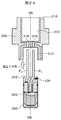
- FIG. 1A is a longitudinal sectional view of an igniter 200 according to an embodiment of the present invention
- FIG. 1B is a plan view of FIG. 1A
- the igniter 200 includes a charge holder 201, a header 202, an eyelet 209 fixed to the header 202, and a cover 203, and an igniting agent 204 (igniting agents 204a and 204b) is enclosed in a space surrounded by these. ing.
- a bridge is formed between the electrodes composed of the first electrode (one end of the first conductive pin 206 (P1)) and the second electrode (the other end of the eyelet 209 connected to one end of the second conductive pin 207 (P2)).
- the wires 205 are electrically connected.
- the first and second electrode sides (base portions) of the conductive pins (P1, P2) are sealed with a resin insulating layer.
- Reference numeral 208 denotes a strong insulating material such as a glass member.
- the charge holder, eyelet, and cover are made of metal.
- the coil surface is the center of the first conductive pin (center pin, P1) and the second conductive pin (eyelet pin, P2).
- the flat IC tag 100 is embedded so as to be in a direction perpendicular to the axis OH-OH ′ passing through.
- a metal shield container (igniter collar) 305 is fixed to the outer periphery of the header 202.
- the inside of the igniter collar is a cylindrical connector insertion space (current supply component connection space) 306 covered with resin 312, and the first conductive pin 206 is connected to the current supply component connection space 306. And the second conductive pin 207 protrude.
- a space 314 for arranging the igniter is also formed inside the igniter collar. Further, a positioning groove 310 is provided in a part of the upper end surface 309 of the igniter collar 305.
- an integrated metal shield container (igniter collar) and igniter is defined as an igniter assembly.
- the IC tag 100 may be associated with one of the first conductive pin 206 and the second conductive pin 207, or may be embedded in the header 202 at a position away from the axis OH-OH '.
- Reference numeral 309 denotes an annular flange portion provided at the end of the insertion space 306 of the connector.
- a positioning portion (unevenness) extending in a direction perpendicular to the OH-OH ′ (radial direction).
- Structure) 310 is provided.
- the positioning unit 310 serves as a positioning unit for an IC tag communication reader / writer described later.
- the positioning unit 310 is not limited to the concave-convex structure. For example, the relative positional relationship between the conductive pins (P1, P2) of the igniter 200 and the reader / writer for IC tag communication, such as positioning pins and holes. Any structure may be used as long as it can be fixed.
- the IC tag 100 has a flat plate shape, and the IC tag is disposed at right angles to the axial direction of the conductive pins. That is, the IC tag 100 is flatly installed at the base of the conductive pins (P1, P2) that protrude from the heating element inside the igniter 200 toward the outside. As described above, the IC tag 100 is arranged parallel to and parallel to the surface of the insulating layer (or bridge wire) of the igniter 200 (parallel arrangement). Note that the IC tag 100 does not necessarily have to be placed flat, and may be inclined in the header 202 as necessary in relation to other components.
- the detection unit of the reader / writer for IC tag communication may be configured to be installed so as to be parallel to the surface of the IC tag 100.
- the number of conductive pins is plural, that is, three or more.
- the IC tag 100 is sealed in a resin insulating layer (header 202) constituting the header 202 in the vicinity of the conductive pins (P1, P2). That is, the igniter 200 is inserted into the metal shield container (igniter collar) 305 together with the heat generating elements and the base portions of the conductive pins (P1, P2) therein, and sealed with a resin insulating layer. Therefore, after sealing, only the conductive pins (P1, P2) extend outward, and the IC tag 100 is not originally visible. If the conductive pins (P1, P2) of the igniter 200 are rotated 180 degrees and reversed left and right, they are placed in a metal shield container (igniter collar) 305 (reversely inserted) and sealed with resin. However, the polarity of the conductive pins (P1, P2) is not known in appearance. In FIG. 1B, for convenience of explanation, the IC tag 100 is represented by a dotted line so as to be visible.
- FIG. 2A is a longitudinal sectional view showing a state before the igniter 200 and the igniter collar 305 are assembled together.
- FIG. 2B shows the positional relationship of the IC tag after assembly.
- the metal shield container (igniter collar) 305 Inside the metal shield container (igniter collar) 305 is a connector insertion space 306 and a space 314 in which the igniter 200 is disposed.
- the igniter 200 is arranged in the space 314 in which the igniter 200 is arranged, and the resin 312 is filled to integrate both, thereby assembling the state shown in FIG. 1A.
- the IC tag 100 is embedded in the immediate vicinity of the conductive pin P1.
- the resin 312 is disposed in a metal shield container (igniter collar) 305 for explanation, and the resin 312 has holes 315 and 316 through which conductive pins (P1 and P2) pass. Although formed, this is a hole formed by the conductive pins (P1, P2) when the resin 312 is injected, and the arrangement and holes of the resin 312 are not previously formed in this embodiment. .
- any method may be used as long as FIG. 1A can be realized as a result.
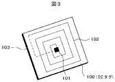
- FIG. 3 is an enlarged perspective view of the IC tag 100.
- the IC tag 100 has an IC tag main body provided on the front surface side of a flat substrate and an IC tag insulating substrate 103 formed on the back surface of the substrate.
- the IC tag main body is composed of an IC chip 101, a planar coil antenna 102 wound around the IC chip 101 in a spiral manner, and a protective material.
- the coil antenna has an inner end connected to the IC chip 101 and an outer end connected to the IC chip 101 via an insulating layer on the back surface.
- UHF and microwave band IC tags can be broadly classified as follows: (1) IC tag with a built-in half-wavelength resonant dipole-based antenna with remarkable wavelength dependence, and (2) wavelength dependence There is an ultra-small IC tag with a side of 10 mm or less that incorporates a resonance circuit using a coil or a capacitor that is not compatible.
- the coil constituting the resonance circuit include a planar coil formed on the flat substrate shown in FIG. 3 and a cylindrical coil (not shown). The coil has a stray capacitance that is not visible to the eye, and a capacitor as a component element may be omitted.
- FIG. 3 shows this omission connection.
- the type of IC tag 100 used in the igniter or igniter assembly of this embodiment may be determined according to the structure of the igniter or igniter assembly. In the case where priority is given to downsizing, the above-mentioned flat micro IC tag is suitable.
- FIG. 4 is a cross-sectional view of a gas generator 300 that employs an igniter assembly.
- the gas generator 300 is composed of a metal shell container having pressure resistance, and has a cylindrical opening at the center thereof, and a pressure resistant metal cylinder container 304 is fixed thereto.
- An igniter 200 is fixed in a space behind the cylindrical container.
- the igniter assembly including the igniter 200 shown in FIG. 4 is slightly different in detail from the igniter assembly shown in FIG. 1A, but in the vicinity of the conductive pins (P1, P2).
- the basic configuration of installing the IC tag 100 in the resin is the same.
- the gas generator molded body 302 is filled on the outside of the metal inner cylindrical container 304 in the gas generator 300.
- 303 is a gas discharge port.
- an ultra-small IC tag is used.
- an ultra-small UHF band tag having an outer dimension of 2.5 mm ⁇ 2.5 mm and a thickness of 0.4 mm (Hitachi Chemical Co., Ltd. IM5-) PK2525 type tag).
- this tag can provide a flight distance of about several millimeters with a predetermined detection radio wave output from an IC tag communication reader / writer.
- the current supply circuit 400 is provided, for example, in an automobile ECU.
- An airbag system mounted on a vehicle includes an ECU including a current supply circuit 400, and a plurality of airbag modules connected to the ECU and each containing a gas generator 300 and an airbag. ing.
- the ECU including the current supply circuit 400 and the individual gas generators 300 are connected to the respective airbag modules by conductors.
- the current supply circuit 400 is formed on a single substrate, for example. At one end of the substrate, connection portions (connection terminals) 401 and 402 for electrically connecting the current supply circuit 400 to the first conductive pin 206 (P1) and the second conductive pin 207 (P2) of the igniter 200 are provided. It has. Here, for the sake of explanation, it is assumed that the first conductive pin 206 is connected to the positive and the second conductive pin 207 is connected to the negative (ground).
- the current supply circuit 400 includes at least switch circuits 410 and 411, pulse generators 412 and 413, a disconnection detection circuit 414, a voltage converter 421, a capacitor 420, and the like arranged on a substrate.
- a battery 430 that is a direct current power source and an igniter 200 incorporated in the gas generator 300 are provided in the middle of a current path through which an ignition key 431 is connected. There are two current paths for each igniter 200, and each is formed by two conductive wires (lead wires).
- the switch circuits 410 and 411, the pulse generators 412 and 413, and the disconnection detection circuit 414 on the substrate are further connected to a microcomputer unit (MCU) 422 via an interface 415.
- a ROM 423 is connected to the MCU 422, and further connected to an impact detection sensor 440, an engine controller, a brake sensor, and the like 450 via an interface 424.
- each igniter 200 is shown in the current supply circuit 400 of FIG. 5, four igniters 200 are shown. These are provided, for example, in an inflator for an airbag in a driver seat, an inflator for an airbag in a passenger seat, and the like.
- the IC tag 100 is embedded in each igniter. In the example of FIG. 5, the IC tag 100 is installed on the first conductive pin (P1) side of each igniter.
- the IC tag 100 obtains unique identification information and manufacturing information such as an ID number of each igniter from the outside, or whether the igniter and the current supply circuit connection units 401 and 402 are appropriately connected ( It is installed to detect reverse insertion).
- the switch circuits 410 and 411 of the electric supply circuit 400 open and close the current path, cut off the direct current when the igniter 200 does not need to be operated, and start supplying the current when the igniter 200 is operated.
- One switch circuit 410, 411 is provided for each current path (for each conductor).
- the disconnection detection circuit is for detecting an abnormality of the igniter (a contact failure between the heat generating portion of the igniter and the ignition agent or a disconnection of the heat generating portion) by a weak current.
- the switch circuits 410 and 411 and the pulse generators 412 and 413 are connected by a conductor, and the switch circuit is opened and closed by sending a control pulse instructing opening and closing of the switch circuit from the pulse generator.
- the control pulse transmission instruction to the pulse generator is sent from the MCU 422 in response to a command from the impact detection sensor 440.
- the switch circuits 410 and 411 are formed by thyristors, MOS-FETs, bipolar transistors, or the like.
- the switch circuit can be provided only on the positive electrode side.
- the capacitor 420 stores a current necessary as a backup power source, and supplies a current instead of the battery when the supply of current from the battery is interrupted.
- a command from the impact detection sensor is sent to the ECU, and a command for closing the switch circuit is transmitted to the pulse generator. Based on this command, the current from the battery is sent to the igniter 200 through the current path as an ignition pulse for igniter operation. In response to this ignition pulse, the explosive in the igniter 200 is ignited and the airbag is deployed.
- the igniter or the igniter assembly itself is small in size, and on the other hand, an IC tag is incorporated that has been very difficult to recognize by labeling or engraving conventionally.
- an IC tag is incorporated into an igniter or an igniter assembly that is small in size and is accompanied by heat and impact during operation.
- the igniter or igniter assembly of the present embodiment includes a driver-seat airbag inflator, a passenger-seat airbag inflator, a side airbag inflator, a curtain inflator, a knee bolster inflator, an inflatable seat belt inflator,
- the present invention can be applied to various inflators (gas generators) such as tubular system inflators and pretensioner inflators.
- the current supply component connected to the conductive pin is limited to the connector of the first embodiment.
- a lead wire connected to the conductive pin by welding, brazing, or the like may be used.
- the igniter assembly Even if the igniter assembly does not need to sense the reverse insertion of the conductive pin, the igniter assembly is combined with an IC tag to analyze the cause and identify the failure range when a failure occurs. It makes sense.
- the igniter used in the igniter assembly may be a case where the number of conductive pins disclosed in Patent Document 5 is one.
- an IC tag is to be incorporated into an igniter assembly that is small in size and has heat and impact during operation, it can be easily embedded from the outside into a resin and properly assembled. Detection can be performed.
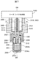
- FIG. 6 is a perspective view of the IC tag communication reader / writer device 500 and the igniter 200.
- the IC tag communication reader / writer device 500 includes an operation unit 501 and a display unit 502 provided on the surface of the main body, a high-frequency antenna circuit (not shown), a power supply and control circuit unit (not shown) provided inside the main body. , And a detection unit 510 provided integrally with the tip of the main body.
- the antenna of the main body and the detection unit 510 are connected by a pair of signal transmission units T (cables) 511 and 512 extending downward from the front end of the main body.
- T signal transmission units
- the antenna circuit inside the main body and the detection unit 510 exposed to the outside are a detection coil (Detecting Coil) of a micro loop having a coil surface in a direction perpendicular to the axes of the pair of cables 511 and 512.
- the number of turns of the detection coil 510 (D) of the micro loop coil is shown as being one turn, but may be two turns or more for convenience of circuit efficiency such as high frequency matching.
- the IC tag communication reader / writer device 500 further includes an engaging portion (concave portion or convex portion) 503, which is a positioning portion (concave / convex structure) having a depth H of the gas generator 300 (or igniter assembly).
- 310 is mechanically fitted to the detection coil of the detection unit 510 at a predetermined position in the cylindrical connector insertion space 306 of the insulating resin of the igniter 200, that is, the IC tag in the igniter 200. 100 is fixed to a detectable position and a predetermined depth H.
- the fitting portion 503 positions the IC tag communication reader / writer device 500 at a predetermined position with respect to the igniter assembly, and the first conductive pin P1 is located near the fitting portion 503 side, and the far side is located. It serves as a mark that distinguishes the time when the second conductive pin P2 is arranged as “correct” and the reverse as “false”. It is assumed that the electromagnetic wave output is adjusted so that the IC tag 100 can be detected when the detection unit 510 is fitted by a predetermined depth H of the fitting unit 503.
- FIG. 7 shows that the fitting portion 503 of the IC tag communication reader / writer device 500 is fitted to the concavo-convex structure 310 of the igniter assembly, and the detection portion 510 is mechanically moved to a predetermined rotational position in the connector insertion space 306.
- the detection unit 510 is inserted into the connector insertion space 306 and is brought close to the IC tag 100.
- the detection coil 510 of the detection unit of the IC tag communication reader / writer device 500 and the coil of the IC tag are electromagnetically coupled, and a secondary current corresponding to the primary current of the detection coil is generated by mutual induction. Induced by coil antenna.
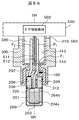
- FIG. 8A and 8B illustrate a configuration in which the state of the first conductive pin P1 and the second conductive pin P2 of the igniter 200 in which the IC tag 100 is embedded is detected in a non-contact manner.
- the IC tag 100 is embedded on the side close to the first conductive pin P1, and the insertion of the first conductive pin P1 and the second conductive pin P2 of the igniter 200 is in a normal state.
- ⁇ 1 indicates a magnetic field line of electromagnetic induction.
- the engaging portion 503 of the IC tag communication reader / writer device 500 corresponds one-to-one with the positioning portion (uneven structure) 310 of the gas generator 300.
- the IC tag communication reader / writer device 500 includes an internal high-frequency antenna circuit to signal transmission units 511 and 512 as a series of detection devices.
- the loop antenna of the detecting portion 510 is connected to the surface of the coil of the IC tag 100 immediately below.
- the detection unit 510 and the IC tag are fixed within a predetermined distance, and in this state, the detection unit 510 and the IC tag are electromagnetically coupled by the magnetic flux ⁇ 1. That is, detection is possible.
- the detection unit 510 is electromagnetically coupled to the loop surface of the IC tag 100 so that external communication is possible via the signal transmission units 511 and 512 by the internal high frequency antenna circuit of the IC tag communication reader / writer device 500 or the like.
- the IC tag coil and the micro loop of the detection unit 510 have a mutual induction relationship corresponding to the primary coil and secondary coil of the transformer.
- the high-frequency current of the signal transmission unit is a primary current
- the lines of magnetic force induced by the primary current generate a secondary current in the coil antenna of the IC tag.
- the IC tag 100 operated with this secondary current returns a signal of identification information such as its ID and other unique information to the internal high-frequency antenna circuit by tracing back the signal transmission unit.
- the sensitivity when viewed from the IC tag communication reader / writer device 500 becomes higher as the signal transmission unit and the tag 100 are closer to each other. Therefore, when the positioning unit 503 matches the concavo-convex structure 310 of the igniter 200, the IC tag 100 is detected immediately below the detection unit 510, and the result is displayed on the display unit 502 of the IC tag communication reader / writer device 500. Is displayed.
- FIG. 8B shows a case where the IC tag 100 'is embedded on the side close to the second conductive pin P2, and the insertion of the first conductive pin P1 and the second conductive pin P2 of the igniter 200 is reversed.
- the IC tag 100 ′ is outside the range that can be detected by the magnetic flux ⁇ 1 ′ of the detection unit 510, and the IC tag communication reader / writer device 500 cannot detect the IC tag 100 ′. Since nothing is displayed on the display unit 502 of the reader / writer device 500 for IC tag communication, it is determined that the state of FIG. 8B is incorrect or there is no IC tag.
- the igniter 200 having the IC tag installed is erroneously rotated 180 degrees, and as a result, the first conductive pin P1 and the second conductive pin P2 are errored and integrated in the reverse direction in the igniter assembly. Then, the position of the IC tag is shifted to the opposite side with respect to the fitting portion 503. In the state of FIG. 8B, the detected electromagnetic wave output and the like are adjusted in advance so that the deviation width becomes an electromagnetic distance that cannot be detected by the detection unit D.
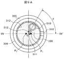
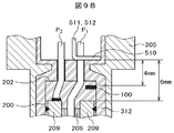
- FIG. 9A is a plan view showing the positional relationship of the detection unit 510 of the IC tag communication reader / writer device 500 in the connector insertion space 306 of the igniter collar 305
- FIG. 9B is a diagram of the detection unit 510 and the igniter 200. It is a longitudinal cross-sectional view which shows an example of positional relationship with an IC tag.
- the detection electromagnetic wave output of the IC tag communication reader / writer device 500 is set to 27 dBm (920 MHz), and the position (rotation angle ⁇ ) of the detection unit 510 is moved by 90 degrees from the position of the IC tag.
- the distance from the detection unit to the metal eyelet 209 is 6 mm
- the facing distance from the IC tag 100 in the middle is 4 mm
- the detection unit 510 The Hitachi Chemical IM5-PK2525 type tag has a coil diameter of 5 mm and an IC tag of 2.5 mm square.
- the rotation angle ⁇ (angle with respect to OV ⁇ OV ′) is 0 °, in other words, the detection unit 510 reliably detects the IC tag 100 under the condition that the detection unit 510 is positioned directly above the IC tag 100 in the configuration of FIG. 8A. did it. However, with the rotation angle ⁇ of 180 °, that is, with the configuration of FIG. 8B, the IC tag 100 could not be detected. Further, the IC tag 100 could not be detected even at a rotation angle ⁇ of ⁇ 90 °, that is, at a position perpendicular to OV-OV ′. According to this detection experiment example, the detection unit 510 indicates that the IC tag 100 can be reliably detected pinpoint at a predetermined facing position.
- the IC tag in the insulating layer of the igniter assembly, information can be obtained by the IC tag when an abnormality is confirmed in the completed igniter assembly, and the cause analysis and malfunction can be prevented. It is possible to specify the generated range.
- the IC tag is embedded in the igniter assembly having the metal shield container, and the connector connection space in the metal shield container can be used for the detection of the IC tag.
- the IC tag information corresponding to each igniter can be efficiently detected from outside by the IC tag communication reader / writer device 500 etc. without affecting the characteristics of the igniter assembly even after being mounted on the vehicle body. it can. Further, it is possible to efficiently detect the back pin of the conductive pin of the ignition circuit without affecting the characteristics of the electrical components of the single igniter assembly after completion of assembly, such as the bridge wire 205 and the ignition agent 204. .
- the IC tag communication reader / writer device 500 does not have to have an integral structure.
- each part of the reader / writer device such as the signal transmission unit T511 to the IC tag is separately configured, These may be connected to each other by cable or electromagnetically wirelessly.
- the IC tag communication reader / writer device 500 includes a main body having an IC tag communication reader / writer antenna and a signal transmission unit and a detection unit provided separately from the main body.
- the antenna has a dipole antenna and communicates between the two with the same electromagnetic wave as that for IC tag communication.
- the dipole antenna is provided with a positioning portion corresponding to the uneven structure of the igniter 200.
- the gas generator 300 According to the assembling method of the gas generator 300 adopting the present embodiment, not only the unique identification information such as the ID number unique to the igniter is acquired, but also the first conductive pin P1 and the second conductive pin P2 of the igniter assembly. After the positional relationship is determined, it is attached to the gas generator 300. After determining whether the insertion state of the two conductive pins of the gas generator is correct or not in this way, the gas generator is incorporated into a known automobile safety device (pretensioner for a seat belt retractor), and the gas generator is further installed. After being incorporated into an airbag device (for example, a seat belt pretensioner), it is mounted on a vehicle.
- a known automobile safety device pretensioner for a seat belt retractor
- an airbag device for example, a seat belt pretensioner
- the two conductive pins of the igniter assembly can be easily determined at a lower cost than the conventional method. For this reason, even in the assembly of automobile safety devices such as airbag devices (airbag gas generators) and seat belt pretensioners, the electrodes of the ignition power source corresponding to each conductive pin can be used without replacing the two conductive pins. It can be assembled to fit and the reliability for these devices is also improved.
- the determination method of the present invention can also be used for an igniter having three or more conductive pins and an igniter assembly.
- the positioning part of the igniter assembly of the present invention is not limited to the one secured by a mechanical structure.
- an optical detection mechanism is employed.
- the means for fixing the relative positional relationship between the igniter assembly and the IC tag communication reader / writer is not limited to a mechanical structure.
- a detection mark is provided as a positioning portion for the IC tag communication reader / writer on the surface of the flange portion 309 in FIG. 1B, and this is detected by a camera provided in the IC tag communication reader / writer for image processing. It may be replaced with an optical detection structure for confirming the relative positional relationship.
- a detection mark is provided on the surface of the flange portion 309 of the igniter assembly as a positioning portion for the reader / writer for IC tag communication. Then, the reader / writer device or the igniter assembly is placed on a table or a robot arm that can be moved in XY coordinates, and the mark on the positioning portion is detected by a camera provided on the reader / writer for IC tag communication. After processing, the relative positional relationship between the two is confirmed, and the reader / writer device and the igniter assembly are accurately positioned, and then reverse insertion is detected in the same manner as in the first embodiment.
- the IC tag is embedded at a predetermined position of the igniter assembly, so that the backlash detection of the conductive pin can be efficiently performed without contact from the outside without affecting the characteristics of the igniter assembly. It can be performed.
- DESCRIPTION OF SYMBOLS 100 ... IC tag, 101 ... IC chip, 102 ... Coil antenna, 200 ... Igniter, 201 ... Charge holder, 202 ... Header, 203 ... Resin cover, 204 ... Ignition agent (ignition agent), 205 ... Bridge wire, 206 ... 1st conductive pin (P1), 207 ... 2nd conductive pin (P2), 209 ... Eyelet, 300 ... Gas generator, 301 ... Transfer agent, 302 ... Gas generating agent molded body, 303 ... Gas discharge port, 305 ... Igniter collar (metal shield container), 306 ... connector insertion space, 309 ...
- annular flange part for holding metal shield container, 310 ... positioning part, 312 ... resin, 315 ... hole, 316 ... hole, 500 ... IC tag communication reader / writer device, 503... Engaging portion, 510... Detecting portion, H.
Landscapes
- Engineering & Computer Science (AREA)
- General Engineering & Computer Science (AREA)
- Physics & Mathematics (AREA)
- Fluid Mechanics (AREA)
- Mechanical Engineering (AREA)
- Computer Hardware Design (AREA)
- Microelectronics & Electronic Packaging (AREA)
- Air Bags (AREA)
- Geophysics And Detection Of Objects (AREA)
Priority Applications (6)
| Application Number | Priority Date | Filing Date | Title |
|---|---|---|---|
| EP13878623.1A EP2977272B1 (de) | 2013-03-18 | 2013-03-18 | Zünderbaugruppe sowie system und verfahren zur detektion besagter zünderbaugruppe |
| JP2015506404A JP6018699B2 (ja) | 2013-03-18 | 2013-03-18 | 点火器及び点火器組立体及びその検知システム並びに検知方法 |
| PCT/JP2013/057710 WO2014147721A1 (ja) | 2013-03-18 | 2013-03-18 | 点火器及び点火器組立体及びその検知システム並びに検知方法 |
| CN201380074791.6A CN105050867B (zh) | 2013-03-18 | 2013-03-18 | 点火器、点火器组装体及其检测系统以及检测方法 |
| KR1020157025359A KR101715545B1 (ko) | 2013-03-18 | 2013-03-18 | 점화기 및 점화기 조립체 및 그 검지 시스템 및 검지 방법 |
| US14/777,931 US9688235B2 (en) | 2013-03-18 | 2013-03-18 | Igniter, igniter assembly, and detection system and detection method therefor |
Applications Claiming Priority (1)
| Application Number | Priority Date | Filing Date | Title |
|---|---|---|---|
| PCT/JP2013/057710 WO2014147721A1 (ja) | 2013-03-18 | 2013-03-18 | 点火器及び点火器組立体及びその検知システム並びに検知方法 |
Publications (1)
| Publication Number | Publication Date |
|---|---|
| WO2014147721A1 true WO2014147721A1 (ja) | 2014-09-25 |
Family
ID=51579456
Family Applications (1)
| Application Number | Title | Priority Date | Filing Date |
|---|---|---|---|
| PCT/JP2013/057710 Ceased WO2014147721A1 (ja) | 2013-03-18 | 2013-03-18 | 点火器及び点火器組立体及びその検知システム並びに検知方法 |
Country Status (6)
| Country | Link |
|---|---|
| US (1) | US9688235B2 (de) |
| EP (1) | EP2977272B1 (de) |
| JP (1) | JP6018699B2 (de) |
| KR (1) | KR101715545B1 (de) |
| CN (1) | CN105050867B (de) |
| WO (1) | WO2014147721A1 (de) |
Cited By (1)
| Publication number | Priority date | Publication date | Assignee | Title |
|---|---|---|---|---|
| EP3009310A1 (de) * | 2014-10-15 | 2016-04-20 | Skidata Ag | Verfahren zur lokalisierung von insassenschutz- und rückhaltesystemen eines verunfallten kraftfahrzeugs |
Families Citing this family (13)
| Publication number | Priority date | Publication date | Assignee | Title |
|---|---|---|---|---|
| US10611330B2 (en) * | 2016-05-13 | 2020-04-07 | Joyson Safety Systems Acquisition Llc | Smart initiator assembly |
| JP6813997B2 (ja) * | 2016-09-02 | 2021-01-13 | 株式会社ダイセル | エアバッグ装置を備えた小型飛行体 |
| JP6706190B2 (ja) * | 2016-11-29 | 2020-06-03 | 株式会社ダイセル | ガス発生器 |
| CN107248565B (zh) * | 2017-07-12 | 2019-11-15 | 北京昆兰新能源技术有限公司 | 主动高压隔离电池箱及其动高压隔离连接器 |
| JP7266412B2 (ja) * | 2019-01-18 | 2023-04-28 | 日本化薬株式会社 | ガス発生器 |
| KR102336178B1 (ko) | 2019-05-31 | 2021-12-08 | (주)고려엔지니어링 | 점화 장치 진단용 센서 및 이의 조립 방법 |
| KR102199142B1 (ko) | 2019-05-31 | 2021-01-06 | (주)파워피디 | 점화 장치 진단 시스템 및 방법 |
| DE102020124056A1 (de) * | 2020-09-15 | 2022-03-17 | Bayerische Motoren Werke Aktiengesellschaft | Verfahren und Steuergerät zum Schutz vor unautorisiertem Verbau einer pyrotechnischen Komponente |
| US12422237B2 (en) * | 2020-10-29 | 2025-09-23 | Ryan Parasram | Addressable ignition stage for enabling a detonator/ignitor |
| CN113324447B (zh) * | 2021-04-30 | 2023-07-07 | 物华能源科技有限公司 | 一种火工品测试装置 |
| CN117412886A (zh) * | 2021-05-11 | 2024-01-16 | 株式会社大赛璐 | 点火器组装体和气体发生装置 |
| DE102021113570A1 (de) | 2021-05-26 | 2022-12-01 | Zf Automotive Germany Gmbh | Mikrogasgenerator und Verfahren zur Herstellung eines Mikrogasgenerators |
| US20240253589A1 (en) * | 2023-02-01 | 2024-08-01 | Autoliv Asp, Inc. | Automotive protective device tracking |
Citations (13)
| Publication number | Priority date | Publication date | Assignee | Title |
|---|---|---|---|---|
| US3971320A (en) | 1974-04-05 | 1976-07-27 | Ici United States Inc. | Electric initiator |
| JPH02595A (ja) * | 1987-10-08 | 1990-01-05 | Tokyo Keiki Co Ltd | メモリパッケージの位置決め構造 |
| US5686691A (en) | 1995-12-22 | 1997-11-11 | Oea, Inc. | Slurry-loadable electrical initiator |
| JP2003136905A (ja) * | 2001-11-01 | 2003-05-14 | Daifuku Co Ltd | 輪体および移動体および輪体の製造方法 |
| JP2006514383A (ja) * | 2002-12-18 | 2006-04-27 | シンボル テクノロジーズ インコーポレイテッド | 光符号読取及びrfid読取を確認するためのシステム及び方法 |
| JP2006125650A (ja) * | 2004-10-26 | 2006-05-18 | Asahi Kasei Chemicals Corp | 無線icタグ付き雷管または点火具 |
| JP2006282091A (ja) * | 2005-04-04 | 2006-10-19 | Honda Motor Co Ltd | タイヤ情報転送装置、タイヤ情報転送方法および車両 |
| JP2007062492A (ja) | 2005-08-30 | 2007-03-15 | Honda Motor Co Ltd | エアバッグ装置 |
| JP2007226574A (ja) | 2006-02-23 | 2007-09-06 | Hamamatsu Toa Denki Kk | 無線タグ内蔵電子部品 |
| JP2008013031A (ja) * | 2006-07-05 | 2008-01-24 | Honda Motor Co Ltd | 着火装置 |
| JP2008090813A (ja) | 2006-09-04 | 2008-04-17 | Hitachi Information Systems Ltd | 小型金属rfidタグおよび該小型金属rfidタグを内装する金属製タグならびに小型金属rfidタグアクセスシステム |
| JP2009272768A (ja) * | 2008-05-01 | 2009-11-19 | Fujitsu Ltd | 無線タグ及び無線タグを有する導電性パイプ |
| JP2011109552A (ja) * | 2009-11-20 | 2011-06-02 | Fujitsu Ltd | 無線タグ |
Family Cites Families (23)
| Publication number | Priority date | Publication date | Assignee | Title |
|---|---|---|---|---|
| ATE258124T1 (de) * | 1998-09-28 | 2004-02-15 | Daicel Chem | Luftsack-gasgenerator und luftsacksystem |
| ATE287279T1 (de) * | 1999-02-16 | 2005-02-15 | Daicel Chem | Filter für einen mehrstufigen gasgenerator für einen airbag und airbagvorrichtung |
| JP2002000595A (ja) * | 2000-06-22 | 2002-01-08 | Toshiba Corp | 永久磁石形モータおよびct装置 |
| US7119693B1 (en) | 2002-03-13 | 2006-10-10 | Celis Semiconductor Corp. | Integrated circuit with enhanced coupling |
| WO2004025210A1 (ja) * | 2002-08-30 | 2004-03-25 | Nippon Kayaku Kabushiki Kaisha | 自動発火機能を有する小型ガス発生器 |
| US7210703B2 (en) | 2004-10-26 | 2007-05-01 | Autoliv Asp, Inc. | One-piece initiator device for inflators |
| DE102005009644B4 (de) * | 2005-03-03 | 2013-09-12 | Schott Ag | Zündvorrichtung für eine pyrotechnische Schutzvorrichtung, Verfahren zur Herstellung einer solchen Zündvorrichtung sowie Gasgenerator mit einer solchen Zündvorrichtung |
| US20060260498A1 (en) * | 2005-04-05 | 2006-11-23 | Daicel Chemical Industries, Ltd. | Igniter assembly |
| US7934453B2 (en) | 2005-06-02 | 2011-05-03 | Global Tracking Solutions Pty Ltd | Explosives initiator, and a system and method for tracking identifiable initiators |
| JP4996481B2 (ja) * | 2006-01-06 | 2012-08-08 | 日本化薬株式会社 | 点火装置ならびにエアバッグ用ガス発生装置およびシートベルトプリテンショナー用ガス発生装置 |
| US8733250B2 (en) * | 2006-01-27 | 2014-05-27 | Schott Ag | Metal-sealing material-feedthrough and utilization of the metal-sealing material feedthrough with an airbag, a belt tensioning device, and an ignition device |
| JP4705550B2 (ja) * | 2006-10-26 | 2011-06-22 | 日本化薬株式会社 | スクイブならびにエアバッグ用ガス発生装置およびシートベルトプリテンショナー用ガス発生装置 |
| JP4668889B2 (ja) * | 2006-12-01 | 2011-04-13 | 日本化薬株式会社 | 点火素子搭載コンデンサ、ヘッダーアッシー、スクイブならびにエアバッグ用ガス発生装置およびシートベルトプリテンショナー用ガス発生装置 |
| US7950693B2 (en) * | 2008-05-20 | 2011-05-31 | Autoliv Asp, Inc. | Dual stage inflator |
| AU2009308168B2 (en) * | 2008-10-24 | 2014-10-30 | Battelle Memorial Institute | Electronic detonator system |
| JP4644296B2 (ja) * | 2009-07-29 | 2011-03-02 | 昭和金属工業株式会社 | ガス発生器 |
| MX2012003701A (es) * | 2009-10-15 | 2012-06-01 | Nippon Kayaku Kk | Composicion de agente generador de gas y producto moldeado del mismo y generador de gas que usa la misma. |
| CN102289689B (zh) * | 2010-05-11 | 2014-05-14 | 株式会社日立系统 | 使用了ic标签的控制机器的操作状态检测装置 |
| SG186824A1 (en) * | 2010-07-15 | 2013-02-28 | Nippon Kayaku Kk | Ignition powder composition for igniter |
| JP5638963B2 (ja) * | 2011-01-07 | 2014-12-10 | 日本化薬株式会社 | ガス発生器 |
| DE102012217070A1 (de) * | 2012-09-21 | 2014-03-27 | Karsten Schwuchow | Anzünderträger, Anzündeinheit und Verfahren zur Herstellung einer Anzündeinheit |
| JP5985950B2 (ja) * | 2012-10-04 | 2016-09-06 | 株式会社ダイセル | ガス発生器とその組立方法 |
| JP6243404B2 (ja) * | 2013-03-29 | 2017-12-06 | 日本化薬株式会社 | ガス発生器 |
-
2013
- 2013-03-18 WO PCT/JP2013/057710 patent/WO2014147721A1/ja not_active Ceased
- 2013-03-18 EP EP13878623.1A patent/EP2977272B1/de active Active
- 2013-03-18 CN CN201380074791.6A patent/CN105050867B/zh active Active
- 2013-03-18 JP JP2015506404A patent/JP6018699B2/ja active Active
- 2013-03-18 KR KR1020157025359A patent/KR101715545B1/ko active Active
- 2013-03-18 US US14/777,931 patent/US9688235B2/en active Active
Patent Citations (13)
| Publication number | Priority date | Publication date | Assignee | Title |
|---|---|---|---|---|
| US3971320A (en) | 1974-04-05 | 1976-07-27 | Ici United States Inc. | Electric initiator |
| JPH02595A (ja) * | 1987-10-08 | 1990-01-05 | Tokyo Keiki Co Ltd | メモリパッケージの位置決め構造 |
| US5686691A (en) | 1995-12-22 | 1997-11-11 | Oea, Inc. | Slurry-loadable electrical initiator |
| JP2003136905A (ja) * | 2001-11-01 | 2003-05-14 | Daifuku Co Ltd | 輪体および移動体および輪体の製造方法 |
| JP2006514383A (ja) * | 2002-12-18 | 2006-04-27 | シンボル テクノロジーズ インコーポレイテッド | 光符号読取及びrfid読取を確認するためのシステム及び方法 |
| JP2006125650A (ja) * | 2004-10-26 | 2006-05-18 | Asahi Kasei Chemicals Corp | 無線icタグ付き雷管または点火具 |
| JP2006282091A (ja) * | 2005-04-04 | 2006-10-19 | Honda Motor Co Ltd | タイヤ情報転送装置、タイヤ情報転送方法および車両 |
| JP2007062492A (ja) | 2005-08-30 | 2007-03-15 | Honda Motor Co Ltd | エアバッグ装置 |
| JP2007226574A (ja) | 2006-02-23 | 2007-09-06 | Hamamatsu Toa Denki Kk | 無線タグ内蔵電子部品 |
| JP2008013031A (ja) * | 2006-07-05 | 2008-01-24 | Honda Motor Co Ltd | 着火装置 |
| JP2008090813A (ja) | 2006-09-04 | 2008-04-17 | Hitachi Information Systems Ltd | 小型金属rfidタグおよび該小型金属rfidタグを内装する金属製タグならびに小型金属rfidタグアクセスシステム |
| JP2009272768A (ja) * | 2008-05-01 | 2009-11-19 | Fujitsu Ltd | 無線タグ及び無線タグを有する導電性パイプ |
| JP2011109552A (ja) * | 2009-11-20 | 2011-06-02 | Fujitsu Ltd | 無線タグ |
Non-Patent Citations (1)
| Title |
|---|
| See also references of EP2977272A4 |
Cited By (1)
| Publication number | Priority date | Publication date | Assignee | Title |
|---|---|---|---|---|
| EP3009310A1 (de) * | 2014-10-15 | 2016-04-20 | Skidata Ag | Verfahren zur lokalisierung von insassenschutz- und rückhaltesystemen eines verunfallten kraftfahrzeugs |
Also Published As
| Publication number | Publication date |
|---|---|
| JPWO2014147721A1 (ja) | 2017-02-16 |
| EP2977272B1 (de) | 2018-03-14 |
| JP6018699B2 (ja) | 2016-11-02 |
| EP2977272A1 (de) | 2016-01-27 |
| CN105050867B (zh) | 2017-06-09 |
| US20160052481A1 (en) | 2016-02-25 |
| EP2977272A4 (de) | 2016-10-26 |
| KR101715545B1 (ko) | 2017-03-13 |
| KR20150120437A (ko) | 2015-10-27 |
| CN105050867A (zh) | 2015-11-11 |
| US9688235B2 (en) | 2017-06-27 |
Similar Documents
| Publication | Publication Date | Title |
|---|---|---|
| JP6018699B2 (ja) | 点火器及び点火器組立体及びその検知システム並びに検知方法 | |
| US9945645B2 (en) | Igniter assembly, airbag system, and detection system and detection method for same | |
| ES2350906T3 (es) | Dispositivo de conexión eléctrica que comprende unos medios de indicación de estado de emparejamiento. | |
| JP2006073394A (ja) | Icタグ実装ハーネス、およびハーネス実装方法 | |
| JP4904397B2 (ja) | タイヤセンサモジュール及びその製造方法 | |
| US9633301B2 (en) | IC module, dual IC card, and method for manufacturing IC module | |
| CN113165454A (zh) | 功能部件 | |
| CN111052148A (zh) | 带无线ic标签的容器以及无线ic标签 | |
| US20050215294A1 (en) | Surface acoustic wave sensor and radio frequency identification interrogator fixture | |
| EP3879253A1 (de) | Rfid-antenne, rfid-etikett und vorrichtung zur messung der physikalischen quantität | |
| US11942731B1 (en) | Apparatus and methods for verification of interchangeable connectors | |
| JP4397731B2 (ja) | 点火装置 | |
| JP2001186002A (ja) | 近接スイッチ | |
| JP6601597B1 (ja) | 無線通信デバイス、およびそれを備えた物品 | |
| JP2019095906A (ja) | バンド型電子タグ、バンド型電子タグ用の記録装置、および管理システム | |
| JP6778750B2 (ja) | イニシエータ電流遮断器 | |
| HK40050265A (en) | Rfid antenna, rfid tag, and physical quantity measurement device | |
| HK40097501A (en) | Rubber product rfid tag and method for manufacturing rubber product rfid tag | |
| JPWO2014147723A1 (ja) | Icタグ取り付け電子部品組み立て体及びその誤差し検知システム並びに誤差し検知方法 | |
| WO2019215963A1 (ja) | 無線通信デバイス、およびそれを備えた物品 | |
| JP2005310650A (ja) | スイッチ装置 |
Legal Events
| Date | Code | Title | Description |
|---|---|---|---|
| WWE | Wipo information: entry into national phase |
Ref document number: 201380074791.6 Country of ref document: CN |
|
| 121 | Ep: the epo has been informed by wipo that ep was designated in this application |
Ref document number: 13878623 Country of ref document: EP Kind code of ref document: A1 |
|
| ENP | Entry into the national phase |
Ref document number: 2015506404 Country of ref document: JP Kind code of ref document: A |
|
| WWE | Wipo information: entry into national phase |
Ref document number: 2013878623 Country of ref document: EP |
|
| ENP | Entry into the national phase |
Ref document number: 20157025359 Country of ref document: KR Kind code of ref document: A |
|
| WWE | Wipo information: entry into national phase |
Ref document number: 14777931 Country of ref document: US |
|
| NENP | Non-entry into the national phase |
Ref country code: DE |