WO2014147793A1 - Feuille d'éclairage, panneau d'éclairage, écran d'éclairage enroulable/déroulable et procédé de fabrication de feuille d'éclairage - Google Patents
Feuille d'éclairage, panneau d'éclairage, écran d'éclairage enroulable/déroulable et procédé de fabrication de feuille d'éclairage Download PDFInfo
- Publication number
- WO2014147793A1 WO2014147793A1 PCT/JP2013/058110 JP2013058110W WO2014147793A1 WO 2014147793 A1 WO2014147793 A1 WO 2014147793A1 JP 2013058110 W JP2013058110 W JP 2013058110W WO 2014147793 A1 WO2014147793 A1 WO 2014147793A1
- Authority
- WO
- WIPO (PCT)
- Prior art keywords
- light
- layer
- daylighting
- panel
- base material
- Prior art date
- Legal status (The legal status is an assumption and is not a legal conclusion. Google has not performed a legal analysis and makes no representation as to the accuracy of the status listed.)
- Ceased
Links
Images




Classifications
-
- F—MECHANICAL ENGINEERING; LIGHTING; HEATING; WEAPONS; BLASTING
- F21—LIGHTING
- F21S—NON-PORTABLE LIGHTING DEVICES; SYSTEMS THEREOF; VEHICLE LIGHTING DEVICES SPECIALLY ADAPTED FOR VEHICLE EXTERIORS
- F21S11/00—Non-electric lighting devices or systems using daylight
- F21S11/007—Non-electric lighting devices or systems using daylight characterised by the means for transmitting light into the interior of a building
-
- B—PERFORMING OPERATIONS; TRANSPORTING
- B29—WORKING OF PLASTICS; WORKING OF SUBSTANCES IN A PLASTIC STATE IN GENERAL
- B29C—SHAPING OR JOINING OF PLASTICS; SHAPING OF MATERIAL IN A PLASTIC STATE, NOT OTHERWISE PROVIDED FOR; AFTER-TREATMENT OF THE SHAPED PRODUCTS, e.g. REPAIRING
- B29C43/00—Compression moulding, i.e. applying external pressure to flow the moulding material; Apparatus therefor
- B29C43/02—Compression moulding, i.e. applying external pressure to flow the moulding material; Apparatus therefor of articles of definite length, i.e. discrete articles
- B29C43/021—Compression moulding, i.e. applying external pressure to flow the moulding material; Apparatus therefor of articles of definite length, i.e. discrete articles characterised by the shape of the surface
-
- B—PERFORMING OPERATIONS; TRANSPORTING
- B29—WORKING OF PLASTICS; WORKING OF SUBSTANCES IN A PLASTIC STATE IN GENERAL
- B29C—SHAPING OR JOINING OF PLASTICS; SHAPING OF MATERIAL IN A PLASTIC STATE, NOT OTHERWISE PROVIDED FOR; AFTER-TREATMENT OF THE SHAPED PRODUCTS, e.g. REPAIRING
- B29C43/00—Compression moulding, i.e. applying external pressure to flow the moulding material; Apparatus therefor
- B29C43/22—Compression moulding, i.e. applying external pressure to flow the moulding material; Apparatus therefor of articles of indefinite length
- B29C43/28—Compression moulding, i.e. applying external pressure to flow the moulding material; Apparatus therefor of articles of indefinite length incorporating preformed parts or layers, e.g. compression moulding around inserts or for coating articles
-
- B—PERFORMING OPERATIONS; TRANSPORTING
- B29—WORKING OF PLASTICS; WORKING OF SUBSTANCES IN A PLASTIC STATE IN GENERAL
- B29C—SHAPING OR JOINING OF PLASTICS; SHAPING OF MATERIAL IN A PLASTIC STATE, NOT OTHERWISE PROVIDED FOR; AFTER-TREATMENT OF THE SHAPED PRODUCTS, e.g. REPAIRING
- B29C43/00—Compression moulding, i.e. applying external pressure to flow the moulding material; Apparatus therefor
- B29C43/22—Compression moulding, i.e. applying external pressure to flow the moulding material; Apparatus therefor of articles of indefinite length
- B29C43/30—Making multilayered or multicoloured articles
-
- B—PERFORMING OPERATIONS; TRANSPORTING
- B29—WORKING OF PLASTICS; WORKING OF SUBSTANCES IN A PLASTIC STATE IN GENERAL
- B29D—PRODUCING PARTICULAR ARTICLES FROM PLASTICS OR FROM SUBSTANCES IN A PLASTIC STATE
- B29D11/00—Producing optical elements, e.g. lenses or prisms
-
- B—PERFORMING OPERATIONS; TRANSPORTING
- B29—WORKING OF PLASTICS; WORKING OF SUBSTANCES IN A PLASTIC STATE IN GENERAL
- B29D—PRODUCING PARTICULAR ARTICLES FROM PLASTICS OR FROM SUBSTANCES IN A PLASTIC STATE
- B29D11/00—Producing optical elements, e.g. lenses or prisms
- B29D11/0074—Production of other optical elements not provided for in B29D11/00009- B29D11/0073
- B29D11/00798—Producing diffusers
-
- E—FIXED CONSTRUCTIONS
- E06—DOORS, WINDOWS, SHUTTERS, OR ROLLER BLINDS IN GENERAL; LADDERS
- E06B—FIXED OR MOVABLE CLOSURES FOR OPENINGS IN BUILDINGS, VEHICLES, FENCES OR LIKE ENCLOSURES IN GENERAL, e.g. DOORS, WINDOWS, BLINDS, GATES
- E06B9/00—Screening or protective devices for wall or similar openings, with or without operating or securing mechanisms; Closures of similar construction
- E06B9/24—Screens or other constructions affording protection against light, especially against sunshine; Similar screens for privacy or appearance; Slat blinds
-
- E—FIXED CONSTRUCTIONS
- E06—DOORS, WINDOWS, SHUTTERS, OR ROLLER BLINDS IN GENERAL; LADDERS
- E06B—FIXED OR MOVABLE CLOSURES FOR OPENINGS IN BUILDINGS, VEHICLES, FENCES OR LIKE ENCLOSURES IN GENERAL, e.g. DOORS, WINDOWS, BLINDS, GATES
- E06B9/00—Screening or protective devices for wall or similar openings, with or without operating or securing mechanisms; Closures of similar construction
- E06B9/24—Screens or other constructions affording protection against light, especially against sunshine; Similar screens for privacy or appearance; Slat blinds
- E06B9/40—Roller blinds
-
- F—MECHANICAL ENGINEERING; LIGHTING; HEATING; WEAPONS; BLASTING
- F21—LIGHTING
- F21S—NON-PORTABLE LIGHTING DEVICES; SYSTEMS THEREOF; VEHICLE LIGHTING DEVICES SPECIALLY ADAPTED FOR VEHICLE EXTERIORS
- F21S11/00—Non-electric lighting devices or systems using daylight
-
- G—PHYSICS
- G02—OPTICS
- G02B—OPTICAL ELEMENTS, SYSTEMS OR APPARATUS
- G02B5/00—Optical elements other than lenses
- G02B5/02—Diffusing elements; Afocal elements
- G02B5/0205—Diffusing elements; Afocal elements characterised by the diffusing properties
- G02B5/021—Diffusing elements; Afocal elements characterised by the diffusing properties the diffusion taking place at the element's surface, e.g. by means of surface roughening or microprismatic structures
- G02B5/0231—Diffusing elements; Afocal elements characterised by the diffusing properties the diffusion taking place at the element's surface, e.g. by means of surface roughening or microprismatic structures the surface having microprismatic or micropyramidal shape
-
- G—PHYSICS
- G02—OPTICS
- G02B—OPTICAL ELEMENTS, SYSTEMS OR APPARATUS
- G02B5/00—Optical elements other than lenses
- G02B5/02—Diffusing elements; Afocal elements
- G02B5/0205—Diffusing elements; Afocal elements characterised by the diffusing properties
- G02B5/0236—Diffusing elements; Afocal elements characterised by the diffusing properties the diffusion taking place within the volume of the element
- G02B5/0242—Diffusing elements; Afocal elements characterised by the diffusing properties the diffusion taking place within the volume of the element by means of dispersed particles
-
- G—PHYSICS
- G02—OPTICS
- G02B—OPTICAL ELEMENTS, SYSTEMS OR APPARATUS
- G02B5/00—Optical elements other than lenses
- G02B5/02—Diffusing elements; Afocal elements
- G02B5/0205—Diffusing elements; Afocal elements characterised by the diffusing properties
- G02B5/0236—Diffusing elements; Afocal elements characterised by the diffusing properties the diffusion taking place within the volume of the element
- G02B5/0247—Diffusing elements; Afocal elements characterised by the diffusing properties the diffusion taking place within the volume of the element by means of voids or pores
-
- G—PHYSICS
- G02—OPTICS
- G02B—OPTICAL ELEMENTS, SYSTEMS OR APPARATUS
- G02B5/00—Optical elements other than lenses
- G02B5/02—Diffusing elements; Afocal elements
- G02B5/0273—Diffusing elements; Afocal elements characterized by the use
- G02B5/0278—Diffusing elements; Afocal elements characterized by the use used in transmission
-
- B—PERFORMING OPERATIONS; TRANSPORTING
- B29—WORKING OF PLASTICS; WORKING OF SUBSTANCES IN A PLASTIC STATE IN GENERAL
- B29C—SHAPING OR JOINING OF PLASTICS; SHAPING OF MATERIAL IN A PLASTIC STATE, NOT OTHERWISE PROVIDED FOR; AFTER-TREATMENT OF THE SHAPED PRODUCTS, e.g. REPAIRING
- B29C43/00—Compression moulding, i.e. applying external pressure to flow the moulding material; Apparatus therefor
- B29C43/22—Compression moulding, i.e. applying external pressure to flow the moulding material; Apparatus therefor of articles of indefinite length
- B29C43/222—Compression moulding, i.e. applying external pressure to flow the moulding material; Apparatus therefor of articles of indefinite length characterised by the shape of the surface
-
- B—PERFORMING OPERATIONS; TRANSPORTING
- B29—WORKING OF PLASTICS; WORKING OF SUBSTANCES IN A PLASTIC STATE IN GENERAL
- B29C—SHAPING OR JOINING OF PLASTICS; SHAPING OF MATERIAL IN A PLASTIC STATE, NOT OTHERWISE PROVIDED FOR; AFTER-TREATMENT OF THE SHAPED PRODUCTS, e.g. REPAIRING
- B29C43/00—Compression moulding, i.e. applying external pressure to flow the moulding material; Apparatus therefor
- B29C43/22—Compression moulding, i.e. applying external pressure to flow the moulding material; Apparatus therefor of articles of indefinite length
- B29C43/24—Calendering
-
- B—PERFORMING OPERATIONS; TRANSPORTING
- B29—WORKING OF PLASTICS; WORKING OF SUBSTANCES IN A PLASTIC STATE IN GENERAL
- B29K—INDEXING SCHEME ASSOCIATED WITH SUBCLASSES B29B, B29C OR B29D, RELATING TO MOULDING MATERIALS OR TO MATERIALS FOR MOULDS, REINFORCEMENTS, FILLERS OR PREFORMED PARTS, e.g. INSERTS
- B29K2101/00—Use of unspecified macromolecular compounds as moulding material
-
- B—PERFORMING OPERATIONS; TRANSPORTING
- B29—WORKING OF PLASTICS; WORKING OF SUBSTANCES IN A PLASTIC STATE IN GENERAL
- B29L—INDEXING SCHEME ASSOCIATED WITH SUBCLASS B29C, RELATING TO PARTICULAR ARTICLES
- B29L2031/00—Other particular articles
- B29L2031/778—Windows
-
- E—FIXED CONSTRUCTIONS
- E06—DOORS, WINDOWS, SHUTTERS, OR ROLLER BLINDS IN GENERAL; LADDERS
- E06B—FIXED OR MOVABLE CLOSURES FOR OPENINGS IN BUILDINGS, VEHICLES, FENCES OR LIKE ENCLOSURES IN GENERAL, e.g. DOORS, WINDOWS, BLINDS, GATES
- E06B9/00—Screening or protective devices for wall or similar openings, with or without operating or securing mechanisms; Closures of similar construction
- E06B9/24—Screens or other constructions affording protection against light, especially against sunshine; Similar screens for privacy or appearance; Slat blinds
- E06B2009/2405—Areas of differing opacity for light transmission control
-
- E—FIXED CONSTRUCTIONS
- E06—DOORS, WINDOWS, SHUTTERS, OR ROLLER BLINDS IN GENERAL; LADDERS
- E06B—FIXED OR MOVABLE CLOSURES FOR OPENINGS IN BUILDINGS, VEHICLES, FENCES OR LIKE ENCLOSURES IN GENERAL, e.g. DOORS, WINDOWS, BLINDS, GATES
- E06B9/00—Screening or protective devices for wall or similar openings, with or without operating or securing mechanisms; Closures of similar construction
- E06B9/24—Screens or other constructions affording protection against light, especially against sunshine; Similar screens for privacy or appearance; Slat blinds
- E06B2009/2417—Light path control; means to control reflection
Definitions
- the present invention relates to a daylighting sheet, a daylighting panel, a roll-up daylighting screen, and a method for manufacturing the daylighting sheet, which are devices for taking outside light such as sunlight into a building or the like.
- Patent Document 1 discloses a light control sheet for controlling sunlight intake that is disposed in a light intake unit that incorporates sunlight into a building, and the entire sheet is made of a light-transmitting material that transmits sunlight.
- the light-transmitting part and a light-shielding part group made of a light-absorbing material that absorbs sunlight, and the light-shielding part group includes a plurality of light-shielding parts made of a light-absorbing material at a predetermined pitch in one direction in the sheet.
- a light control sheet characterized by being arranged is disclosed.
- outside light such as sunlight is transmitted in a desired direction using an interface having a refractive index difference having a predetermined geometric shape such as a prism. It is deflected and reflected to control.
- JP 2010-259406 A International Publication WO93 / 25792 JP 2003-157707 A JP 2000-15712 A
- the present invention has an object to provide a daylighting sheet that can be efficiently lit and can be viewed from the indoor side when applied to a building opening such as a window.
- a daylighting panel, a roll-up daylighting screen using the daylighting sheet, and a method for manufacturing the daylighting sheet are provided.
- the invention according to claim 1 is a daylighting sheet that is disposed in an opening of a building and transmits light from the outdoor side to the indoor side, and is formed by laminating a plurality of layers.
- At least one other layer having translucency is disposed on the side of the light deflection layer opposite to the base material layer.
- the invention according to claim 3 is the daylighting sheet according to claim 1 or 2, wherein the light transmission portion has a predetermined cross section and extends in one direction along one surface of the base material layer, Arranged in a direction different from the extending direction, the light deflecting portion extends between the light transmitting portions by being disposed between the adjacent light transmitting portions, and is disposed in the different direction.
- the light deflecting portion is filled with a material that reflects light.
- the light deflection section is filled with a material that scatters and transmits light.
- the light deflection section is filled with a material having a lower refractive index than the light transmission section.
- the light deflection section is a gap.
- the invention according to claim 8 is the daylighting sheet according to any one of claims 1 to 7, further comprising a layer including at least one of an ultraviolet ray absorbing function, a heat ray absorbing function, and a near infrared ray absorbing function. ing.
- the invention according to claim 9 is a daylighting panel comprising: a plate-like panel having translucency; and the daylighting sheet according to any one of claims 1 to 8 attached to one surface of the panel. It is.
- the invention according to claim 10 is the window glass provided with the panel in the opening of the building in the daylighting panel according to claim 9.
- Invention of Claim 11 is a rollup provided with the lighting sheet of any one of Claims 1 thru
- the invention according to claim 12 is a method for producing the daylighting sheet according to any one of claims 1 to 8, wherein the shape of the base material to be the base material layer and the light transmitting portion can be transferred.
- Light-filling part is formed by filling the mold roll with a curable resin before curing, which becomes a light-transmitting part, and curing the curable resin after filling and then releasing from the mold roll. It is a manufacturing method of a sheet.
- the daylight can be efficiently taken, and the outdoor side can be seen from the indoor side when applied to an opening such as a window of a building.
- the manufacturing method of the lighting sheet of this invention such a lighting sheet can be manufactured efficiently.
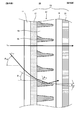
- FIG. 6 is an enlarged view of a part of the light deflection layer 17 of the daylighting panel 40.
- FIG. 4 is a diagram for explaining an example of an optical path in the light deflection layer 17.
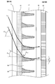
- FIG. 6 is an enlarged view of a part of the light deflection layer 57.
- FIG. 13A is a diagram for explaining the light deflection unit 59 ′
- FIG. 13B is a diagram for explaining the light deflection unit 59 ′′.
- 6 is a diagram for explaining an example of an optical path in the light deflection layer 57.
- FIG. 10 is a diagram illustrating another example of an optical path in the light deflection layer 57.
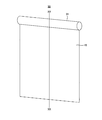
- FIG. 4 is a perspective view of a roll-up daylighting screen 90.
- FIG. It is the figure which showed the cross section of the daylighting sheet
- FIG. 4 is a perspective view of a roll-up daylighting screen 140.
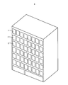
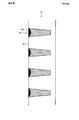
- FIG. 1 is a diagram illustrating a first embodiment, and is an external perspective view of a building 1 provided with a window 2 (see FIG. 2).
- the building 1 is a so-called office building, and an outer wall facing the south side is provided with a plurality of openings communicating with the interior and the exterior, and a window 2 having a daylighting panel 10 is disposed therein.
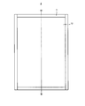
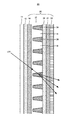
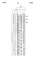
- FIG. 2 is a view of the window 2 to which the daylighting panel 10 is formed by the daylighting sheet 15 (see FIG. 3) and the daylighting panel 10 is applied as seen from the front.
- the window 2 includes a daylighting panel 10 and a frame 3 arranged so as to border the panel 11 along at least the outer peripheral portion of the daylighting panel 10 (see FIG. 3). .
- the window 2 is disposed in the opening of the building 1.
- the window is formed by providing the frame and the panel in the frame in the same manner as the known configuration. Therefore, a well-known frame 3 can be used.
- the window 2 can also be formed by sticking the daylighting sheet 15 to a window previously arranged in the building. At this time, since the building is usually provided with a panel and a frame that borders the outer periphery thereof, the window 2 can be formed by attaching a daylighting sheet 15 to the panel.
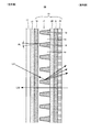
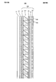
- FIG. 3 is a cross-sectional view in the vertical direction along the line indicated by III-III in FIG. 2, focusing on the daylighting panel 10, and schematically showing the layer structure.
- FIG. 3 for ease of viewing, some of the repeated symbols are omitted (the same applies to the following drawings).
- the daylighting panel 10 has a panel 11 and a daylighting sheet 15 attached to the panel 11 with an adhesive layer 12.
- the daylighting sheet 15 includes a base material layer 16, a light deflection layer 17, an adhesive layer 20, a protective layer 21, and a hard coat layer 22.
- FIG. 3 the lighting panel 10 is shown in a posture attached to a building or the like so that the left side of FIG. 3 is the outdoor side, the right side is the indoor side, the upper side is the top, and the lower side is the top side. Become the ground.
- the panel 11 is a translucent plate-like translucent panel used for a normal building or vehicle window, such as a window glass or a resin panel. Therefore, a known plate glass or resin panel can be used as a member constituting the panel 11.
- the window glass may be used as the panel 11 arranged in advance in the building as described above. That is, the daylighting panel 10 can also be formed by sticking the daylighting sheet 15 to a window provided in the building.
- the adhesive layer 12 is a layer for adhering the daylighting sheet 15 to the panel 11.
- the material constituting the adhesive layer 12 is not particularly limited as long as such adhesion is possible, and known pressure-sensitive adhesives, adhesives, photocurable resins, thermosetting resins, and the like can be used. If an adhesive is illustrated, an acrylic adhesive can be mentioned, for example, More specifically, there exists an adhesive which combined the acrylic copolymer and the isocyanate compound.
- the material constituting the adhesive layer 12 is preferably made of a material excellent in translucency and weather resistance due to the properties of the daylighting panel 10.
- the thickness of the adhesive layer 12 is not particularly limited, but is preferably 10 ⁇ m or more and 100 ⁇ m or less. If the adhesive layer 12 is too thin, the adhesion between the panel 11 and the daylighting sheet 15 may be reduced. If the adhesive layer 12 is too thick, it is difficult to make the thickness of the adhesive layer 12 uniform.
- the adhesive layer 12 may have a function of absorbing at least one of infrared rays, ultraviolet rays, and visible rays. “Absorb at least one of infrared, ultraviolet, and visible light” means to absorb electromagnetic waves of a predetermined wavelength among electromagnetic waves classified into infrared, ultraviolet, and visible light. “Absorb” means to absorb 10% or more of the electromagnetic wave having the predetermined wavelength.
- an absorbent capable of absorbing at least one of infrared light, ultraviolet light, and visible light may be contained.
- Examples of the absorber that absorbs infrared rays include metal oxide ultrafine particles such as antimony-doped tin oxide (ATO) or tin-doped indium oxide (ITO) and phthalocyanine compounds. Infrared light can be absorbed by adding these absorbents or applying them to the surface. By adding the function of absorbing infrared rays to the daylighting sheet in this way, for example, there is an effect that, for example, the use of cooling can be suppressed by suppressing the increase in the indoor temperature especially in summer.
- ATO antimony-doped tin oxide
- ITO tin-doped indium oxide
- phthalocyanine compounds phthalocyanine compounds. Infrared light can be absorbed by adding these absorbents or applying them to the surface.
- Benzotriazole ultraviolet absorbers (TINUVIN P, TINUVIN P FL, TINUVIN 234, TINUVIN 326, TINUVIN 326 FL, TINUVIN 328, TINUVIN 329, TINUVIN 329 FL, all manufactured by BASF Japan Ltd.)
- triazine UV absorber (TINUVIN 1577 ED, manufactured by BASF Japan Ltd.)
- benzophenone UV absorber (CHIMASSORB 81, CHIMASORB 81 FL, all manufactured by BASF Japan Ltd.), benzoate UV absorber (TINUVIN 120, BASF) Japan Co., Ltd.).
- Ultraviolet rays can be absorbed by adding these absorbents or applying them to the surface. By adding a function of absorbing ultraviolet rays to the daylighting sheet, for example, there are effects such as suppressing adverse effects on the skin of people in the room and fading of furniture in the room.
- the absorbent that absorbs visible light light-absorbing colored particles such as carbon black are preferably used.
- the present invention is not limited to this, and for example, colored particles that selectively absorb a specific wavelength in accordance with the characteristics of light to be absorbed may be used.
- the colored particles include organic fine particles colored with metal salts such as carbon black, graphite and black iron oxide, dyes, pigments, colored glass beads, and the like.
- colored organic fine particles are preferable from the viewpoints of cost, quality, availability, and the like. More specifically, acrylic crosslinked fine particles containing carbon black, urethane crosslinked fine particles containing carbon black, and the like are preferable. Visible light can be absorbed by adding these absorbents or applying them to the surface. By adding a function of absorbing visible light to the daylighting sheet, for example, glare in the room can be reduced.
- the absorbing agent only needs to be able to absorb electromagnetic waves having a predetermined wavelength among electromagnetic waves classified into infrared rays, ultraviolet rays, and visible rays, and may be configured to absorb only infrared rays, or absorb only ultraviolet rays. You may comprise so that only visible light may be absorbed, and you may comprise so that 2 or more types of electromagnetic waves among infrared rays, an ultraviolet-ray, and visible light can be absorbed. Which wavelength of the electromagnetic wave can be absorbed can be appropriately selected according to the installation location and the installation purpose of the daylighting sheet.
- the wavelength and absorption factor of the electromagnetic wave to absorb can be adjusted by adjusting suitably the kind and quantity of an absorber mentioned above.
- the absorption rate of the electromagnetic wave of the said predetermined wavelength in the layer containing an absorber is 10% or more, and it is preferable that it is 90% or less. If the absorption rate is less than 10%, it is difficult to obtain the effect of containing the absorbent, and if it is 90% or less, the composition constituting the absorbent can be easily adjusted.
- the base material layer 16 is a layer serving as a base material for forming the light deflection layer 17 and has a light transmitting property and supports the light deflection layer 17 so as to prevent deformation.
- a transparent resin mainly composed of one or more of acrylic, styrene, polycarbonate, polyethylene terephthalate, acrylonitrile, and the like, epoxy acrylate, and urethane acrylate
- the reactive resin ionizing radiation curable resin etc.
- the thickness of the base material layer 16 is not particularly limited, but is preferably 25 ⁇ m or more and 300 ⁇ m or less. If the thickness of the base material layer 16 is out of this range, there is a possibility of causing a problem in workability. For example, if the base material layer 16 is too thin, wrinkles are likely to occur. Moreover, if the base material layer 16 is too thick, it will become difficult to wind up in an intermediate process.
- the light deflection layer 17 is a layer capable of diffusing light incident from one surface side (especially light incident from obliquely upward as described later) and emitting it to the other surface side.
- the light deflection layer 17 has a cross section shown in FIG. 3 and a shape extending to the back / near side of the drawing. That is, in the cross section shown in FIG. 3, a trapezoidal light transmission portion 18 and a light deflection portion 19 in which a cross section formed between adjacent light transmission portions 18 is formed in a trapezoidal recess.
- the base material layer 16 side of the light transmitting portion 18 is connected.
- the light transmitting unit 18 and the light deflecting unit 19 have the cross section and extend in one direction (horizontal direction in the present embodiment) of the sheet surface, and a plurality of light transmission units 18 and light deflecting units 19 in a direction different from the one direction (vertical direction in the present embodiment).
- the light transmission part 18 and the light deflection part 19 are arranged. Any part of the light deflection layer 17 may contain an absorbent capable of absorbing at least one of infrared light, ultraviolet light, and visible light.
- an infrared absorber it is cool because it is easy to absorb infrared rays in the light deflection layer in summer when the solar altitude is high, and it is warm and comfortable in the winter environment because it is difficult to absorb infrared rays in the light deflection layer in winter when the solar altitude is low. Can be.
- the light transmitting portion 18 is a portion that transmits light, and it is preferable that the surface on the base material layer 16 side of the light transmitting portion 18 and the opposite surface (surface on the protective layer 21 side) are formed in parallel. .
- the light transmitting portion 18 transmits light without being scattered. This improves the visibility of the backside scenery.
- “transmits without scattering light” means a portion formed without adding a material that intentionally scatters, and inevitably occurs when light passes through the material. Scattering is allowed to occur.
- the material constituting the light transmission portion 18 may be the same as or different from that of the base material layer 16. However, if there is a difference in refractive index between the two, the possibility of light being deflected at the interface increases, so even if they are the same material or different materials, the refractive index difference is small or there is no refractive index difference. It is preferable.
- the base material layer 16 and the light transmission part 18 can also be formed integrally.
- the base material layer 16 and the light transmission part 18 are separately formed, You may laminate
- Examples of the material constituting the light transmitting portion 18 include transparent resins mainly composed of one or more of acrylic, styrene, polycarbonate, polyethylene terephthalate, acrylonitrile, and reactive resins such as epoxy acrylate and urethane acrylate (ionizing radiation curing). Mold resin).
- the light transmission parts 18 are arranged in parallel at predetermined intervals in the direction along the sheet surface. Therefore, a recess having a trapezoidal cross section is formed between adjacent light transmission portions 18.
- the concave portion is a groove having a trapezoidal cross section having a lower base on the upper bottom side of the light transmitting portion 18 and an upper base on the lower bottom side of the light transmitting portion 18.
- the light deflection unit 19 is formed. That is, in the cross section shown in FIG. 3, the light transmitting portion 18 has a trapezoidal cross section having a lower base on the surface on the base material layer 16 side and an upper base shorter than the lower base on the opposite surface. It is an element having
- the light deflecting unit 19 is a part that deflects the light that has reached here, and in this embodiment, the light deflecting unit 19 is configured to diffuse and reflect the light that has arrived.
- a light deflection unit 19 can be formed, for example, by filling the recesses between the adjacent light transmission units 18 with the following materials.
- the material constituting the light deflection unit 19 is preferably a concealing material, such as a white pigment or a silver pigment.
- the white pigment include metal oxides such as titanium oxide, titanium dioxide, magnesium oxide, and zinc oxide.
- examples of the silver pigment include metals such as aluminum and chromium.
- the interface between the light transmission unit 18 and the light deflection unit 19 may be a matte surface.
- the light deflecting portion 19 Since the light deflecting portion 19 is thus formed in the recess between the adjacent light transmitting portions 18, the shape thereof also follows the recess. Therefore, in this embodiment, the light deflecting portion 19 has a substantially trapezoidal cross section having a short upper base on the base material layer 16 side and a long lower bottom on the protective layer 21 side, and has a hypotenuse therebetween. This hypotenuse constitutes an interface with the light transmission portion 18 and becomes a common hypotenuse.
- the angle ⁇ 1 of the hypotenuse in the cross section of the light deflection unit 19 is preferably 0 ° or more and 20 ° or less with respect to the normal to the sheet surface. ⁇ less than 1 is 0 degrees (which in cross-section appearing in FIG. 3, it means that the width of the base material layer 16 side width than the protective layer 21 side of the light deflection unit 19 is shorter shape.) to become so If the light deflection portion 19 is formed, it becomes difficult to produce a mold used for forming the light deflection layer 17 as will be described later, and even if it is produced, there may be a problem in releasability. .
- the aspect ratio of the height (the size of the light deflection layer 17 in the thickness direction) to the opening width (the width on the protective layer 21 side of the light deflection unit 19 in the cross section shown in FIG. 3) is set. It becomes difficult to increase the size, and it becomes difficult to obtain a desired effect described later by the light deflection layer 17.
- the pitch at which the light deflection portions 19 are arranged is not particularly limited, but is preferably 10 ⁇ m or more and 200 ⁇ m or less, and more preferably 100 ⁇ m or more and 200 ⁇ m or less. If the pitch of the light deflecting portions 19 is too narrow, it is difficult to obtain a desired effect, which will be described later, by the light deflecting layer 17, and there is a possibility that an image transmitted through the light transmitting portion 18 becomes rainbow-like due to the diffraction phenomenon. is there. Further, if the pitch of the light deflection portions 19 is too wide, it becomes difficult to form the light deflection portions 19, or mold releasability and workability when producing the light deflection layer 17 as described later. May cause problems.
- the opening width of the light deflector 19 (the width on the protective layer 21 side in the cross section shown in FIG. 3) is not particularly limited, but is preferably 5 ⁇ m or more and 150 ⁇ m or less. If the opening width of the light deflection unit 19 is too narrow, it is difficult to obtain a desired effect described later by the light deflection layer 17. Further, if the opening width of the light deflection unit 19 is too wide, it becomes difficult to form the light deflection unit 19, or when the light deflection layer 17 is manufactured as described later, mold releasability or processing There is a risk of problems with sex.
- the thickness of the light deflection layer 17 is not particularly limited, but is preferably 50 ⁇ m or more and 300 ⁇ m or less. If the light deflection layer 17 is too thin, it may be difficult to obtain a desired effect, which will be described later, or it may be difficult to perform fine processing (formation of the light deflection portion 19 or the like). On the other hand, if the light deflection layer 17 is too thick, there is a risk of problems in workability such as difficulty in releasing the mold when producing the light deflection layer 17 as described later.
- the shapes of the light transmitting part and the light deflecting part are not limited to the form shown in FIG. Therefore, in the cross section corresponding to the cross section shown in FIG. 3, the light transmission portion may be rectangular, and the portion corresponding to the hypotenuse of the trapezoid is curved (the tangent of the curve is the same as the above ⁇ 1 in each portion) there is preferred.) or line-shaped (have each line constituting a polygonal line may be made it is preferable.) is the same conditions as above theta 1.
- the adhesive layer 20 is a layer for attaching the protective layer 21 to the opposite side of the light deflection layer 17 from the base material layer 16, and various types having such a function can be used.
- the material used for the adhesive layer 20 is not particularly limited, but the same material as the adhesive layer 12 can be used.
- the preferable thickness of the adhesive layer 20 is the same as that of the adhesive layer 12.
- the protective layer 21 is a layer that is paired with the base material layer 16 and is disposed so as to sandwich the light deflection layer 17, and has a function of protecting the light deflection layer 17 together with the base material layer 16. If the protective layer 21 has such a function, the material will not be specifically limited, For example, it can comprise by the material similar to the above-mentioned base material layer 16. FIG.
- the hard coat layer 22 is a layer provided on the outermost surface of the daylighting panel 10 opposite to the panel 11 for the purpose of surface protection.
- the hard coat layer 22 can be formed as a transparent resin layer, and is preferably formed as a cured resin layer formed by curing a curable resin from the viewpoint of resistance to scratches and surface contamination.
- an ionizing radiation curable resin other known curable resins, or the like may be appropriately employed according to the required performance.
- the ionizing radiation curable resin include acrylate-based, oxetane-based, and silicone-based resins.
- acrylate-based ionizing radiation curable resins include monofunctional (meth) acrylate monomers, bifunctional (meth) acrylate monomer monomers, (meth) acrylate monomers such as trifunctional or higher (meth) acrylate monomers, urethane ( It consists of (meth) acrylate ester oligomers such as (meth) acrylate, epoxy (meth) acrylate, and polyester (meth) acrylate, or (meth) acrylate prepolymers.
- tri- or higher functional (meth) acrylate monomers examples include trimethylolpropane tri (meth) acrylate, pentaerythritol tetra (meth) acrylate, dipentaerythritol hexa (meth) acrylate, and the like.
- the hard coat layer 22 may be added with a function of improving the stain resistance. This can be achieved, for example, by adding a silicone compound, a fluorine compound, or the like. Further, as other functions, it may have a function of improving antistatic properties and water repellency.
- materials that can be used for improving the antistatic property PEDOT-PSS (PEDOT (Poly (3,4-ethylenedioxythiophene); 3,4-ethylenedioxythiophene polymer) and PSS (polynesylsulfonate) are used for the electron conduction type. ); Coexistence with a styrene sulfonic acid polymer)), and the ionic conductive type includes lithium salt materials. Examples of materials that can be used for improving water repellency include fluorine compounds.
- the daylighting panel 10 described above can be manufactured as follows, for example.
- the daylighting panel 10 can be manufactured by bonding the daylighting sheet 15 to the panel 11 with the adhesive layer 12.
- the lighting sheet 15 is produced as follows, for example.
- the light deflection layer 17 is formed by a method using a mold roll. That is, a mold roll is prepared in which irregularities capable of transferring the light transmitting portion 18 of the light deflection layer 17 are provided on the outer peripheral surface of the cylindrical roll. And the base material used as the base material layer 16 is inserted between a mold roll and the nip roll arrange
- the above-described composition is preferable as the composition constituting the light transmission part 18, but more specifically, as follows. That is, the photocurable resin composition which mix
- Examples of the photocurable prepolymer (P1) include epoxy acrylate-based, urethane acrylate-based, polyether acrylate-based, polyester acrylate-based, and polythiol-based prepolymers.
- Examples of the reactive dilution monomer (M1) include vinyl pyrrolidone, 2-ethylhexyl acrylate, ⁇ -hydroxy acrylate, and tetrahydrofurfuryl acrylate.
- Examples of the photopolymerization initiator (I1) include hydroxybenzoyl compounds (2-hydroxy-2-methyl-1-phenylpropan-1-one, 1-hydroxycyclohexyl phenyl ketone, benzoin alkyl ether, etc.), benzoyl Formate compounds (such as methylbenzoylformate), thioxanthone compounds (such as isopropylthioxanthone), benzophenones (such as benzophenone), phosphate compounds (1,3,5-trimethylbenzoyldiphenylphosphine oxide, bis (2,4,6- Trimethylbenzoyl) -phenylphosphine oxide and the like, and benzyldimethyl ketal and the like.
- benzoyl Formate compounds such as methylbenzoylformate
- thioxanthone compounds such as isopropylthioxanthone
- benzophenones such as benzophenone
- phosphate compounds (1,3,5-
- the irradiation device for curing the photocurable resin composition and the curability of the photocurable resin composition can be arbitrarily selected.
- 2-hydroxy-2-methyl-1-phenylpropan-1-one, 1-hydroxycyclohexyl phenyl ketone and bis (2,4,6-trimethylbenzoyl) are preferable.
- -Phenylphosphine oxide is preferable.
- photocurable prepolymer (P1), reactive diluent monomer (M1), and photopolymerization initiator (I1) can be used alone or in combination of two or more.
- the composition constituting the light transmission part 18 sandwiched between the mold roll and the base material and filled therein is irradiated with light from the base material side by a light irradiation device.
- the composition which comprises the light transmissive part 18 can be hardened, and the shape can be fixed.
- molded light transmission part 18 are released from a metal mold
- the light deflecting portion 19 can be formed by filling the concave portion of the light transmitting portion 18 with the composition constituting the light deflecting portion 19 and curing it. Specifically, an excessive amount of the composition constituting the light deflection unit 19 is supplied to the recess of the light transmission unit 18, and the amount is adjusted by scraping off the excess with a blade, and the recess is filled with the composition. . Then, the composition filled in the recess is cured by an appropriate method. In this way, the light deflection layer 17 can be formed on the base material layer 16.
- a laminate in which the hard coat layer 22 is laminated on one surface of the protective layer 21 and the adhesive layer 20 is laminated on the other surface is laminated so that the adhesive layer 20 of this laminate is in contact with the light deflection layer 17.
- the adhesive layer 20 is made of an ultraviolet curable resin, a photocurable resin, or the like, it may be cured by irradiating with ultraviolet rays or light after lamination.
- the daylighting sheet 15 produced as described above is bonded to the panel 11 with the adhesive layer 12 to obtain the daylighting panel 10.
- an absorbent that can absorb at least one of infrared rays, ultraviolet rays, and visible light may be contained in any one of the above-described layers instead of the adhesive layer 12.
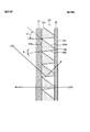
- FIG. 3 shows a schematic optical path example. Note that the optical path example is conceptually shown, and does not strictly represent the degree of refraction or reflection.
- External light L31 irradiated to the daylighting panel 10 from obliquely above where sunlight is assumed passes through the panel 11, the adhesive layer 12, and the base material layer 16, and reaches the light deflection unit 19 of the light deflection layer 17.
- the external light L31 that has reached the light deflector 19 is deflected by the light deflector 19. In this embodiment, it is deflected by diffuse reflection. Then, the diffusely reflected light passes through the adhesive layer 20, the protective layer 21, and the hard coat layer 22, and enters the indoor side. At this time, since the light incident on the indoor side is deflected upward and diffused at that time, it is possible to prevent the direct exposure of the external light, and further, a wide range of the indoor side space can be prevented by the external light. Illuminate.
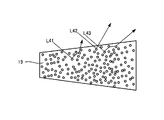
- FIG. 4 is a diagram for explaining diffuse reflection with a view focusing on one light deflection unit 19.
- the external lights L41, L42, and L43 that have reached the light deflector 19 are emitted in different directions, for example, by being repeatedly reflected by a substance that reflects the light contained in the light deflector 19. Is diffused and deflected.
- the light deflecting unit 19 can reflect the outside light without actively absorbing it during the deflection, so that the light can be taken in efficiently. It can also be adopted.
- the observer's line of sight is based on the light L32 in FIG. That is, the outdoor can be observed through the surface on the base material layer 16 side of the light transmitting portion 18 that is a surface parallel to the panel 11 and the opposite side surface. Since there is no large refraction at the interface in this part, it is possible to see the outdoor scene clearly.
- the outside scenery can be seen relatively clearly from the room side while the outside light is efficiently taken into the room. Further, since the light deflection layer 17 is sandwiched between the base material layer 16 and the protective layer 21, durability can be improved.
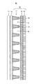
- FIG. 5 is a diagram for explaining the second embodiment, and is a cross-sectional view schematically showing the layer configuration of the daylighting panel 30, and corresponds to FIG.
- the same components as those of the daylighting panel 10 are denoted by the same reference numerals, and description thereof will be omitted.
- the daylighting panel 30 includes a panel 11, an adhesive layer 12, and a daylighting sheet 35.
- the daylighting sheet 35 includes a base material layer 16, a light deflection layer 37, an adhesive layer 20, a protective layer 21, and a hard coat layer 22.
- the daylighting panel 30 is different from the daylighting panel 10 in that a light deflection layer 37 is applied instead of the light deflection layer 17 of the daylighting panel 10 described above. In other respects, the daylighting panel 30 is the same as the daylighting panel 10.
- the light deflection unit 19 of the light deflection layer 17 provided in the daylighting panel 10 diffuses and reflects the light
- the light deflection unit 39 of the light deflection layer 37 diffuses the light while transmitting it.
- the shape of the light deflection unit 39 is the same as that of the light deflection unit 19, and the material filled therein is different from that of the light deflection unit 19.
- a material that diffuses the transmitted light while transmitting it is disposed in the light deflecting unit 39.
- a material obtained by mixing a transparent binder resin and a transparent diffusing agent having a refractive index different from that of the binder resin is preferable.
- the diffusing agent include crosslinked particles obtained by polymerizing monomers mainly composed of (meth) acrylic acid ester and styrene.
- the crosslinked particles Ganzpearl manufactured by Aika Industry Co., Ltd. may be mentioned.
- the cross-linked particles can be controlled in refractive index by changing the mixing ratio of acrylic acid ester and styrene.
- the refractive index can be made about 1.49 by increasing the acrylic ratio, and the refractive index can be made about 1.59 by increasing the styrene ratio.
- urethane cross-linked particles can be used as the diffusing agent.
- Specific examples of the urethane crosslinked particles include Art Pearl manufactured by Negami Kogyo Co., Ltd.
- the diffusing agent can also be made into hollow particles.
- FIG. 5 shows a schematic optical path example.
- External light L51 irradiated on the daylighting panel 30 from obliquely above where sunlight is assumed passes through the panel 11, the adhesive layer 12, and the base material layer 16, and reaches the light deflection portion 39 of the light deflection layer 37.
- the external light L51 that has reached the light deflection unit 39 enters the light deflection unit 39, and diffuses while passing through the light deflection unit 39 due to the above-described configuration of the light deflection unit 39.
- the light transmitted through the light deflection layer 39 in this way is then transmitted through the adhesive layer 20, the protective layer 21, and the hard coat layer 22 and is incident on the indoor side. At this time, since the light incident on the indoor side is diffused and deflected, it is possible to prevent the direct exposure of the external light, and it is possible to illuminate a wide range of the indoor space with the external light.
- the light deflector 39 can be taken indoors without actively absorbing outside light, so that light can be taken in efficiently.
- the daylighting panel 30 it is possible to view the outside scenery relatively clearly from the indoor side while efficiently taking outside light into the indoor side. Further, since the light deflection layer 37 is sandwiched between the base material layer 16 and the protective layer 21, durability can also be improved.
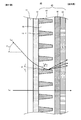
- FIG. 6 is a diagram for explaining the third embodiment, which is a cross-sectional view schematically showing the layer structure of the daylighting panel 40, and corresponds to FIG.
- the same components as those in FIG. 3 are denoted by the same reference numerals, and description thereof will be omitted.
- the lighting panel 40 includes a panel 11, an adhesive layer 12, and a daylighting sheet 45 bonded to the panel 11 by the adhesive layer 12.
- the daylighting sheet 45 includes the light deflection layer 17, the base material layer 16, and the hard coat layer 22.
- the light deflection layers 17 and 37 are sandwiched between the base material layer 16 and the protective layer 21, but in the daylighting panel 40, the light deflection layer 17 is formed between the panel 11 and the base material layer 16. Is sandwiched. Even if it is this form, durability can be improved like the lighting panels 10 and 30.
- the light deflection layer 17 can be configured as follows.
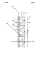
- FIG. 7 shows an enlarged view of a part of the light deflection layer 17.
- the light transmission unit 18 is disposed between the two light deflection units 19 as described above. Therefore, as shown by VIIa in FIG. 7, a line corresponding to the diagonal line of the light transmitting portion 18 can be defined.
- the indoor side end of the side of the light deflection unit 19 disposed below and the outdoor side of the side of the light deflection unit 19 disposed adjacently above the line VIIa connecting the end and the estimated line, ⁇ lump line VIIa is a corner towards 90 degrees or less of the horizontal plane and the angle between viewing angle theta a.
- the ⁇ a takes a predetermined value.
- the leg portion in the trapezoidal section of the light deflecting portion 19 has an upper leg portion inclined by ⁇ U with respect to the horizontal plane (the normal of the sheet surface of the daylighting sheet 40). and, legs comprising the lower side are inclined with a similarly theta D.
- FIG. 8 shows light L S1 from the sun as an example of one optical path.
- L S1 is applied to the daylighting panel 40 at an elevation angle (angle formed from a horizontal plane) ⁇ S1 based on the solar altitude at that time.
- the light L S1 incident on the daylighting panel 40 travels through the light transmitting portion 18 of the light deflection layer 17 while passing through the daylighting panel 40.
- the light transmission part 18 if the refractive index of the light transmission part is N P and the outdoor refractive index is N 0 , the light L S1 travels at the sunlight advancing angle ⁇ P1 represented by the equation (1). .
- FIG. 9 An explanatory diagram is shown in FIG.
- the elevation angle ⁇ SH when the south-high altitude is highest in a year is considered. That is, when sunlight enters the daylighting panel 40 at an elevation angle ⁇ SH when the altitude is the highest at least in one year, ⁇ a is set from the viewpoint of causing all direct light from the sunlight to reach the light deflector 19. Can be prescribed.
- the limit for the light L SH incident at the elevation angle ⁇ SH to reach the light deflecting unit 19 is the situation where the light L SH travels along the prospective line in the light transmitting unit 18. That is, it is only necessary that the sunlight traveling angle ⁇ PH in the light transmitting portion 18 is the same as the prospective angle ⁇ a . Therefore, this is expressed by the following formula (2) by the relational expression of the refractive index and the incident angle, where N 0 is the refractive index of air and N p is the refractive index of the light transmission part.
- ⁇ SH is an elevation angle at a position where the south-middle altitude is the highest at a predetermined location, there is no elevation angle with a larger angle at the predetermined location. Therefore, in order to reach all of the light deflecting unit 19 similarly to sunlight having a predetermined elevation angle lower than this, while satisfying Expression (1), ⁇ SH of Expression (2) and Expression (3) is further satisfied. Instead, if the predetermined elevation angle is taken into consideration, the value to be taken for ⁇ a can be obtained similarly.
- the light deflecting unit converts direct sunlight from an elevation angle ⁇ SM or higher between the elevation angle ⁇ SH when the south and middle altitudes are highest in the year and the elevation angle ⁇ SL when the south and middle altitudes are the lowest in the year.
- ⁇ SM elevation angle
- ⁇ SL elevation angle
- you want to reach a may be formed yaw angle theta a to satisfy equation (4) while satisfying the equation (3).
- the means for setting the prospective angle ⁇ a to a predetermined angle as described above includes the pitch of the light deflection unit, the angles of the legs of the light deflection unit ( ⁇ U and ⁇ D in FIG. 7), and the thickness direction of the light deflection unit. It can be mentioned that the size is changed in the left-right direction in FIG. It is possible to adjust ⁇ a to a predetermined angle by combining these alone or in combination.
- the lower limit of ⁇ a is not particularly limited.
- the lower limit of ⁇ a is not particularly limited.
- FIG. 10 shows a diagram for explanation. Since the basic idea is the same as the calculation of Expressions (2) and (3), it can be considered that the sunlight L SL by the elevation angle ⁇ SL proceeds along the prospective line as can be seen from FIG. Therefore, Formula (5) can be obtained.
- ⁇ PL is the sunlight advance angle of the light transmission part at the elevation angle ⁇ SL . Therefore, the equation (6) can be obtained from the purpose of obtaining the equations (3) and (5).
- Table 1 shows the elevation angle ( ⁇ SH ) at the highest altitude in the south and middle of the year in Sapporo, Tokyo, and Okinawa, and the elevation angle ( ⁇ SL ) at the lowest altitude in the south and middle of the year. It was.
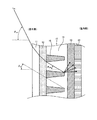
- FIG. 11 is a diagram for explaining the fourth embodiment, and is a cross-sectional view schematically showing the layer structure of the daylighting panel 50 and corresponds to FIG.
- the same components as those in FIG. 3 are denoted by the same reference numerals, and description thereof will be omitted.
- the lighting panel 50 includes a panel 11, an adhesive layer 12, and a daylighting sheet 55 bonded to the panel 11 by the adhesive layer 12.
- the daylighting sheet 55 includes a light deflection layer 57, the base material layer 16, and the hard coat layer 22.
- the light deflection layer 57 has a light transmission part 58 and a light deflection part 59.
- the light transmission part 58 has a cross section shown in FIG. 11 and is arranged so as to extend in one direction along the surface of the base material layer 16 (horizontal direction in the posture arranged in the building 1).
- a plurality of light transmission portions 58 are arranged at a predetermined interval along the surface of the base material layer 16 in a direction different from the direction (vertical direction in the posture arranged in the building 1).
- the adjacent light transmission portions 58 are connected and integrated at the end portion on the base material layer 16 side.
- the light deflection portion 59 is disposed between the adjacent light transmission portions 58.
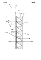
- FIG. 12 shows an enlarged view of a part of the light deflection layer 57.
- the light transmission portion 58 is a portion that transmits light, and the surface on the base material layer 16 side and the opposite side surface (surface on the adhesive layer 12 side) of the light deflection layer 57 where the light transmission portion 58 is disposed. Are formed in parallel.
- the light transmission part 58 transmits light without scattering. This improves the visibility of the backside scenery.
- “transmits without scattering light” means a portion formed without adding a material that intentionally scatters, and inevitably occurs when light passes through the material. Scattering is allowed to occur.
- the light transmitting portion 58 has a substantially trapezoidal cross section between the two light deflecting portions 59 in the cross sections shown in FIGS. 11 and 12, and the outdoor side has a short upper bottom and the indoor side has a long lower bottom.
- Sides constituting the interface with the deflecting portion 59 are leg portions.
- the leg portion has a shape that follows the shape of the light deflection portion 59 described later, it is not necessarily a straight line.
- the material constituting the light transmission part 58 is the same as that of the light transmission part 18 described above.
- the light deflection part 59 is a part formed between two adjacent light transmission parts 58. That is, as described above, the light transmission portions 58 are arranged in parallel in the direction along the sheet surface at a predetermined interval, and a recess having a predetermined shape is formed between the light transmission portions 58.
- the concave portion in the present embodiment is a groove having a cross-sectional shape corresponding to the cross-sectional shape of the light deflection unit 59, and the light deflection unit 59 is formed by filling the material constituting the light deflection unit 59 therein. Accordingly, the light deflection unit 59 has a cross-sectional shape based on the recess.
- the light deflecting unit 59 is a layer configured to be able to deflect the light irradiated here by totally reflecting the light. Therefore, the light deflection unit 59 is filled with a material having a refractive index lower than that of the light transmission unit 58. According to this, if the incident light satisfies the total reflection condition due to the difference in the refractive index between the light deflecting unit 59 and the light transmitting unit 58 and the angle of the light incident on the interface thereof, the light is totally reflected here. Can be reflected and deflected. As will be described in detail later, the direction of the deflected light is changed, and for example, it can be eliminated from direct light that gives glare by irradiating the ceiling.
- the refractive index of the material forming the light deflection portion 59 is preferably in the range of 1.49 to 1.56, more preferably 1.49 to 1.50, from the versatility of the raw materials. Further, the refractive index difference between the light transmitting portion 58 and the light deflecting portion 59 at that time is 0.03 or more and 0.07 or less, more preferably 0.05 or more and 0.06 or less. In the range where the difference in refractive index is larger than 0 and smaller than 0.03, when wavelength dispersion during total reflection (dispersion due to different total reflection angles depending on the wavelength) occurs, long wavelength components are not totally reflected and short. Only the wavelength component may be totally reflected, which may cause a color change.
- the difference in refractive index is larger than 0.06, the refractive index of the short wavelength component tends to be larger than the refractive index of the long wavelength refractive index component, and rainbow-like unevenness may be noticeable. is there.
- the light deflecting unit 59 has the following shape. This will be described with reference to FIG.
- the light deflection unit 59 has a polygonal shape in the cross section shown in FIG. Among them, in the posture in which the daylighting panel 50 is disposed in the building 1, the upper side is formed so that the two sides 59a and 59b are continuous in the indoor / outdoor direction and protrude downward. That is, the side 59a is arranged outside the room, and the side 59b is arranged inside the room.
- the angle ⁇ U1 and the angle ⁇ U2 are also determined from this viewpoint. Details will be described later while showing an example of an optical path.
- the lower side 59d opposite to the sides 59a, 59b has an inclination angle of ⁇ D1 with respect to the horizontal plane (the normal to the sheet surface of the daylighting sheet 55).
- ⁇ D1 is not particularly limited, but is preferably 0 ° or more and 30 ° or less from the viewpoint of manufacturing.
- FIG. 13 illustrates a cross-sectional shape of the light deflection unit according to the modification.
- FIG. 13A shows an example of the light deflection unit 59 ′ in which the upper side is convex downward (ie, concave).
- the inclination angle of the tangent line at the most outdoor part is an angle ⁇ U1 with respect to the horizontal plane (the normal of the sheet surface of the daylighting sheet 50), and the inclination angle of the tangent line at the most indoor part is the horizontal plane (lighting).
- the angle ⁇ U2 may be set with respect to the normal of the sheet surface of the sheet 50.
- FIG. 13B shows an optical deflecting portion in which the upper side is formed by three sides 59 ′′ a, 59 ′′ c, 59 ′′ b from the outdoor side and is convex downward (that is, concave).
- 59 ′′ the inclination angle of the side 59 ′′ a that is the outermost side is an angle ⁇ U1 with respect to the horizontal plane (the normal of the sheet surface of the daylighting sheet 50), and the inclination angle of the side 59 ′′ b that is the most indoor side.
- the light deflection unit including three sides, three sides 59 ′′ a, 59 ′′ c, and 59 ′′ b has been described.
- the present invention is not limited thereto, and may be formed by more sides.
- These light deflecting portions as shown in FIGS. 13A and 13B also have the same effect as the light deflecting portion having the shape shown in FIG. Furthermore, according to the shapes shown in FIGS. 13A and 13B, it is possible to suppress the occurrence of rainbow-like unevenness due to wavelength dispersion due to total reflection.
- FIG. 14 shows light L S2 from the sun as an example of one optical path.
- L S2 is applied to the daylighting panel 50 at an elevation angle (an angle formed from a horizontal plane) ⁇ S2 based on the solar altitude at that time.
- the light L S2 incident on the daylighting panel 50 travels through the light transmitting portion 58 of the light deflection layer 57 while passing through the daylighting panel 50.
- the light transmission part 58 if the refractive index of the light transmission part is N P , and the outdoor refractive index is N 0 , the light L S2 travels at the sunlight advancing angle ⁇ P2 represented by the equation (9). .
- FIG. 15 shows light L S3 from the sun as another example of the optical path.
- L S3 is applied to the daylighting panel 50 at an elevation angle (angle formed from a horizontal plane) ⁇ S3 based on the solar altitude at that time.
- ⁇ S3 is an angle larger than ⁇ S2 .
- the light L S3 incident on the daylighting panel 50 travels through the light transmitting portion 58 of the light deflection layer 57 while passing through the daylighting panel 50.
- the light transmission part 58 if the refractive index of the light transmission part is N P and the outdoor refractive index is N 0 , the light L S3 travels at the sunlight advancing angle ⁇ P3 represented by the equation (10). .
- the light transmitting unit 58 and the light deflecting are performed. If the relationship between the refractive index difference with the portion 59 and the sunlight traveling angle ⁇ P3 is equal to or greater than the total reflection critical angle, total reflection occurs at the interface as shown in FIG. As a result, the light travels through the light transmitting portion 58 at a smaller angle of elevation than the sunlight travel angle ⁇ P3 , reaches a portion where the inclination angle arranged indoors is ⁇ U2 and is totally reflected here.
- the daylighting sheet 50 if the inclination angles ⁇ U1 and ⁇ U2 have a relationship of ⁇ U1 > ⁇ U2 , sunlight having different traveling angles such as light L S2 and L S3. Can be provided indoors by deflecting it with total reflection, and without greatly reducing the amount of sunlight entering the room, and eliminating at least some direct light (so-called direct sunlight) Is possible. Thereby, a bright and comfortable indoor space can be formed.
- the daylighting sheet 50 is provided with the light transmission part 58 as described above, and the front and back surfaces of the light deflection layer 57 at the part where the light transmission part 58 is disposed are formed parallel and smooth. Thereby, the scenery of an outdoor side can be visually recognized from the indoor side like the said other example of a form.
- the deflected direction depends on the sunlight traveling angle ⁇ P that is an angle incident on the interface and ⁇ U1 and ⁇ U2 that are the inclination angles of the light deflecting unit. Therefore, it is preferable that ⁇ U1 and ⁇ U2 are determined so that the totally reflected light finally becomes upward from the horizontal.
- ⁇ U1 > ⁇ U2 it is possible to eliminate at least part of the direct light while efficiently taking sunlight into the room.
- ⁇ U1 and ⁇ U2 that are more preferable from the viewpoint of more effectively totally reflecting sunlight by the light deflecting unit 59 and deflecting the sunlight so as to be emitted indoors. This will be described in detail below.
- ⁇ U1 can set an angle at which the sunlight incident on the daylighting sheet can be appropriately totally reflected when the elevation angle of the sun is high.
- the elevation angle ⁇ SH when the south-high altitude is highest in one year can be set. That is, since the sunlight advancing angle ⁇ PH in the light transmitting portion when the elevation angle ⁇ SH is set is expressed by the above formula (2), ⁇ U1 can totally reflect the light traveling at this angle ⁇ PH. Set.
- elevation theta SH is differs by latitude and a predetermined region extending so as to straddle the different latitudes (e.g.
- ⁇ U2 can set an angle at which sunlight incident on the daylighting sheet can be appropriately totally reflected when the elevation angle of the sun is low.
- the elevation angle ⁇ SL when the altitude is the lowest in one year can be set. That is, since the sunlight advancing angle ⁇ PL in the light transmitting portion when the elevation angle ⁇ SL is set is expressed by the above equation (5), ⁇ U2 can totally reflect the light traveling at this angle ⁇ PL. Set.
- the elevation angle theta PL varies depending latitude, (theta SL1 ⁇ theta SL2) by theta SL1 to theta SL2 in a predetermined region (e.g., country or region etc.) extending so as to straddle the different latitudes, defining a range of theta U2 be able to.
- ⁇ U2 becomes smaller than 0 degrees (inclined in the opposite direction to FIG. 12), manufacturing becomes difficult.
- the expression (13) can be set to a preferable range of ⁇ U2 .
- ⁇ SL in Okinawa is 40.5 degrees, so ⁇ U2 is preferably in the range of the formula (14).
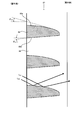
- FIG. 16 is a diagram for explaining the fifth embodiment, which is an enlarged view of a part of the cross section of the light deflection layer 67 included in the fifth embodiment, and corresponds to FIG. Since this embodiment is characterized by the cross-sectional shape of the light deflection layer 67, only the light deflection layer 67 will be described. Other parts are the same as described above.
- the light deflection layer 67 has a light transmission part 68 and a light deflection part 69.
- the light transmission part 68 has a cross section shown in FIG. 16 and is arranged so as to extend in one direction along the surface of the base material layer (horizontal direction in a posture arranged in the building 1).
- a plurality of light transmission portions 68 are arranged at a predetermined interval along the surface of the base material layer in a direction different from the direction (vertical direction in the posture arranged in the building 1).
- the adjacent light transmission portions 68 are connected and integrated at the end on the base material layer side.
- the light deflection section 69 is disposed between the adjacent light transmission sections 68.
- the light transmitting portion 68 is a portion that transmits light, and the surface of the light deflection layer 67 on the base material layer 16 side (see FIG. 11) and the opposite side (the adhesive layer 12) in the portion where the light transmitting portion 68 is disposed. Side, see FIG. 11) and is preferably formed parallel and smooth. This makes it easier to see the outdoor scenery as described above.
- the light transmitting portion 68 has a cross section shown in FIG. 16 and has a substantially trapezoidal cross section between the two light deflecting portions 68.
- the light deflecting portion has a short upper bottom on the outdoor side and a long bottom on the indoor side.
- the side that forms the interface with 69 is a leg.
- the leg portion has a shape along the shape of the light deflection portion 69 described later, it is not necessarily a straight line.
- the light deflection part 69 is a part formed between two adjacent light transmission parts 68. That is, as described above, the light transmissive portions 68 are arranged in parallel in the direction along the sheet surface at a predetermined interval, and a groove-shaped concave portion having a predetermined shape is formed between the light transmissive portions 68.
- the concave portion in this embodiment is a groove having a cross-sectional shape corresponding to the cross-sectional shape of the light deflection unit 69 described later, and the light deflection unit 69 is formed by filling the material constituting the light deflection unit 69 therein. Yes. Therefore, the light deflection unit 69 has a cross-sectional shape based on the recess.
- the light deflection unit 69 is a part configured to be able to deflect the light irradiated here by totally reflecting the light. For this reason, the light deflection unit 69 is filled with a material having a lower refractive index than the light transmission unit 68. According to this, if the incident light satisfies the total reflection condition due to the refractive index difference between the light deflecting unit 69 and the light transmitting unit 68 and the angle of the light incident on the interface thereof, the light is totally reduced here. Can be reflected and deflected. As will be described in detail later, the direction of the deflected light is changed, and for example, it can be eliminated from direct light that gives glare by irradiating the ceiling.
- the refractive index of the material forming the light deflection unit 69 is preferably in the range of 1.49 to 1.56, more preferably 1.49 to 1.50, from the versatility of the raw materials. Further, the refractive index difference between the light transmitting portion 68 and the light deflecting portion 69 at that time is 0.03 or more and 0.07 or less, more preferably 0.05 or more and 0.06 or less. In the range where the difference in refractive index is larger than 0 and smaller than 0.03, when wavelength dispersion during total reflection (dispersion due to different total reflection angles depending on the wavelength) occurs, long wavelength components are not totally reflected and short. Only the wavelength component may be totally reflected, which may cause a color change.
- the refractive index difference is larger than 0.07, the refractive index of the short wavelength component tends to be larger than the refractive index of the long wavelength refractive index component, and rainbow-like unevenness may be remarkably exhibited. is there.
- the light deflection unit 69 has the following shape. This will be described with reference to FIG.
- the light deflecting unit 69 has a shape along the concave portion between the adjacent light transmitting units 68 as described above, but the upper side 69a and the lower side in the posture in which the daylighting panel is arranged in the building in the cross section shown in FIG. Side 69b.
- the upper side 69a is curved so as to be convex upward. Thereby, as described later, it is possible to suppress the light totally reflected by the side 69a of the deflecting unit 69 from being diffused widely and concentrated in a narrow range. Details will be described later while showing an example of an optical path.
- the side 69a is not particularly limited as long as it protrudes upward when it is in the posture shown in FIG. Examples thereof include an example in which the side 69a is formed by a broken line in which a plurality of straight lines are continuous, and an example in which the side 69a is a curve.
- the tangent at an arbitrary position has an angle ⁇ U3 with respect to the horizontal plane (the normal of the sheet surface of the daylighting sheet), and the tangent is directed to the outdoor side (sun side).
- the angle ⁇ U3 at each part of the side 69a continuously changes from the outdoor side toward the indoor side. Thereby, the above effect can be made more remarkable.
- the range of ⁇ U3 is not particularly limited, but it is preferable that ⁇ U3 is larger than 0 degree and smaller than 30 degrees in the center in the indoor / outdoor direction of the light deflection unit 69.
- the edge 69a side 69b of the side serving as the lower of the opposite side, the inclination angle is the theta D3 with respect to the horizontal plane (normal to the sheet surface of the lighting sheet).
- ⁇ D3 is not particularly limited, but is preferably 0 ° or more and 30 ° or less from the viewpoint of manufacturing.
- a daylighting device is formed by the daylighting panel including the daylighting sheet including the deflection layer 67 described above, and this is arranged in the opening of the building 1 as shown in FIG. Next, the action in the scene where the daylighting sheet is arranged in this way will be described based on main light paths.
- An example of an optical path necessary for the explanation is shown in FIG.
- FIG. 16 shows light L S4 and light L S5 from the sun as an example of the optical path.
- the light L S4 and the light L S5 are two parallel lights irradiated at different positions on the lighting panel at an elevation angle (an angle formed from a horizontal plane) based on the solar altitude at that time.
- the light L S4 and the light L S5 incident on the daylighting panel travel through the light transmission portion 68 of the light deflection layer 67 while passing through the daylighting panel 12.
- the daylighting sheet it is possible to eliminate at least a part of direct light (so-called direct sunlight) without greatly reducing the amount of sunlight entering the room. Thereby, a bright and comfortable indoor space can be formed.
- direct sunlight so-called direct sunlight
- the room can be efficiently brightened.
- the daylighting sheet of the present embodiment is provided with the light transmitting portion 68 as described above, and the front and back surfaces of the light deflection layer 67 at the portion where the light transmitting portion 68 is disposed are formed in parallel and smooth. Thereby, the scenery of an outdoor side can be visually recognized from the indoor side like the above-mentioned other forms.
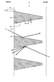
- FIG. 17 is a diagram for explaining the sixth embodiment, which is an enlarged view of a part of the cross section of the light deflection layer 77 included in the sixth embodiment, and corresponds to FIG. Since this embodiment is characterized by the cross-sectional shape of the light deflection layer 77, only the light deflection layer 77 will be described. Other parts are the same as described above.
- the light deflection layer 77 has a light transmission part 78 and a light deflection part 79.
- the light transmission part 78 has a cross section shown in FIG. 17 and is arranged so as to extend in one direction along the surface of the base material layer (horizontal direction in the posture arranged in the building 1).
- a plurality of light transmitting portions 78 are arranged at a predetermined interval along the surface of the base material layer in a direction different from the direction (vertical direction in the posture arranged in the building 1).
- the adjacent light transmission portions 78 are connected and integrated at the end on the base material layer side.
- the light deflection unit 79 is disposed between the adjacent light transmission units 78.
- the light transmitting portion 78 is a portion that transmits light, and the surface on the base material layer 16 (see FIG. 11) side and the opposite side (the adhesive layer 12) of the portion of the light deflection layer 77 where the light transmitting portion 78 is disposed. Side, see FIG. 11) and is preferably formed parallel and smooth. This makes it easier to see the outdoor scenery as in the above-described form.
- the light transmitting portion 78 has a substantially trapezoidal cross section between the adjacent light deflection portions 79 in the cross section shown in FIG. 17, and the light deflection portion has a short upper bottom on the outdoor side and a long bottom bottom on the indoor side.
- the side which comprises the interface with 77 is a leg part.
- the leg portion has a shape that follows the shape of the light deflection portion 79 as described later, the leg portion is not necessarily straight.
- the light deflection part 79 is a part formed between two adjacent light transmission parts 78. That is, as described above, the light transmission parts 78 are arranged in parallel in the direction along the sheet surface at a predetermined interval, and a groove-like recess having a predetermined shape is formed between the light transmission parts 78.
- the concave portion in this embodiment is a groove having a cross-sectional shape corresponding to the cross-sectional shape of the light deflection unit 79, and the light deflection unit 79 is formed by filling the material constituting the light deflection unit 79 therein. Therefore, the light deflector 79 has a cross-sectional shape based on the concave portion.
- the light deflection unit 79 is a part configured to be able to deflect the light irradiated here by totally reflecting the light. Therefore, the light deflection unit 79 is filled with a material having a refractive index lower than that of the light transmission unit 78. According to this, if the incident light satisfies the total reflection condition due to the difference in refractive index between the light deflecting unit 79 and the light transmitting unit 78 and the angle of the light incident on the interface thereof, the light is totally reflected here. Can be reflected and deflected. As will be described in detail later, the direction of the deflected light is changed, and for example, it can be eliminated from direct light that gives glare by irradiating the ceiling.
- the refractive index of the material forming the light deflector 79 is preferably in the range of 1.49 to 1.56, more preferably 1.49 to 1.50, from the versatility of the raw materials. Further, the refractive index difference between the light transmitting portion 78 and the light deflecting portion 79 at that time is 0.03 or more and 0.07 or less, more preferably 0.05 or more and 0.06 or less. In the range where the difference in refractive index is larger than 0 and smaller than 0.03, when wavelength dispersion during total reflection (dispersion due to different total reflection angles depending on the wavelength) occurs, long wavelength components are not totally reflected and short. Only the wavelength component may be totally reflected, which may cause a color change.
- the refractive index difference is larger than 0.07, the refractive index of the short wavelength component tends to be larger than the refractive index of the long wavelength refractive index component, and rainbow-like unevenness may be remarkably exhibited. is there.
- the light deflection unit 79 has the following shape. This will be described with reference to FIG.
- the light deflection section 79 has a trapezoidal shape in the cross section shown in FIG.
- the long lower base is the outdoor side (the upper bottom side of the light transmission part 78), the short upper base is the indoor side (the lower bottom side of the light transmission part 78), and the upper and lower sides are trapezoids.
- the inclination angle thereof is the angle ⁇ U4 with respect to the horizontal plane (the normal of the sheet surface of the daylighting sheet) (outside of the sun) ) Inclined upward.
- the side 79b on the side opposite to the side 79a which is the lower leg portion, has an inclination angle that faces the lower outdoor side at a predetermined angle with respect to the horizontal plane (the normal of the sheet surface of the daylighting sheet). Inclined.
- the inclination angle of the side 79b is not particularly limited, but is preferably 0 ° or more and 30 ° or less from the viewpoint of manufacturing.
- the side 79b is configured to scatter and reflect the light totally reflected here.
- the specific form for scattering and reflecting light is not specifically limited, For example, you may comprise so that the edge
- Such an uneven surface is preferably stepped along the inclination of the side 79b as shown in FIG. Specifically, it is as follows.
- the size of the unevenness in the thickness direction (the size indicated by T in FIG. 17) is desirably 1 ⁇ m or more and 50 ⁇ m or less.
- the thickness direction of the light deflection layer 77 is preferably 50 ⁇ m or more and 300 ⁇ m or less. Therefore, when T is larger than 50 ⁇ m, it may not be stepped. Further, the size of the unevenness in the width direction (the size indicated by S in FIG. 17) is 0.5 ⁇ m or more, more preferably 1.0 ⁇ m or more. On the other hand, the size in the width direction is desirably 10 ⁇ m or less. If it is larger than 10 ⁇ m, the width of the light deflector 79 becomes too close, and there is a possibility that an appropriate step shape is not obtained.
- a daylighting device is formed by the daylighting panel including the daylighting sheet including the deflection layer 77 described above, and this is arranged in the opening of the building 1 as shown in FIG. Next, the action and the like in the scene where the daylighting sheet is arranged in this way will be described based on main light paths.
- the light L S6 is light that is applied to the daylighting panel at an elevation angle (angle formed from a horizontal plane) based on the solar altitude at that time.
- the light L S6 incident on the daylighting panel travels through the light transmitting portion 78 of the light deflection layer 77 while passing through the daylighting panel.
- sunlight that has traveled through the light transmitting portion 78 reaches the interface between the light transmitting portion 78 and the light deflecting portion 79, the relationship between the refractive index difference between the light transmitting portion 78 and the light deflecting portion 79, and the angle of sunlight travel. Is totally reflected at the interface as shown in FIG. As a result, sunlight is deflected and direct light that causes glare can be suppressed.
- light as indicated by L N1 in FIG. 17 is emitted from the indoor side to the outdoor side.
- This light includes information that can be used to indicate the state of the room, and may be totally reflected at the interface between the light transmitting part and the light deflecting part and be emitted in a form that clearly shows this information outside the room.
- light scattering means 79 is provided on the lower side 79b of the light deflector 79, as shown by the light LN1 in FIG. Scattered and emitted outside the room.
- the daylighting sheet including the deflection layer 77 the light reflected from the interface between the light transmission portion and the light deflection portion loses clarity and is emitted to the outside of the room. The state in which you can ask the state of the room from the outside is eliminated.
- FIG. 18 is a diagram for explaining the seventh embodiment, which is an enlarged view of a part of the cross section of the light deflection layer 87 included in the seventh embodiment, and corresponds to FIG. Since this embodiment is characterized by the cross-sectional shape of the light deflection layer 87, only the light deflection layer 87 will be described. Other parts are the same as described above.
- the light deflection layer 87 includes a light transmission portion 88 and a light deflection portion 89.
- the present embodiment is different in that a light absorbing portion 89e, which is a portion that absorbs light, is provided on the outdoor side of the light deflecting portion 89.
- the light absorbing portion 89e is a part configured to absorb the light irradiated here.
- the light absorbing portion 89e is a portion that can absorb visible light (light having a wavelength of 360 nm or more and 830 nm or less) by 10% or more. Unless the absorption factor of visible light in the light absorption part 89e is 10% or more, the light absorption part 89e is difficult to exhibit the function described later. Moreover, it is preferable that the absorption factor of the visible light in the light absorption part 89e is 90% or less. If the absorption factor of visible light in the light absorption part 89e is 90% or less, the composition of the light absorption part 89e can be easily adjusted.
- the thickness of the light absorbing portion 89e (the size in the left-right direction in FIG. 18) is preferably 1 ⁇ m or more and 10 ⁇ m or less. By making the light absorbing portion 89e to such a thickness, it becomes easy to make the visible light absorption rate of the light absorbing portion 89e uniform.
- the light absorption part 89e can be comprised by the composition by which the particle
- the resin having a light transmitting property the same resin as that constituting the light transmitting portion 88 can be used.
- the light absorbing particles light absorbing colored particles such as carbon black are preferably used.
- the present invention is not limited thereto, and for example, colored particles that selectively absorb a specific wavelength in accordance with the characteristics of light to be absorbed may be used as the light absorbing particles.
- the colored particles include organic fine particles colored with metal salts such as carbon black, graphite and black iron oxide, dyes, pigments, colored glass beads, and the like.
- colored organic fine particles are preferable from the viewpoints of cost, quality, availability, and the like. More specifically, acrylic crosslinked fine particles containing carbon black, urethane crosslinked fine particles containing carbon black, and the like are preferable.
- the light absorbing portion 89e is configured as described above, but the shape of the light absorbing portion is not limited as long as it can absorb light.
- Such a light deflection layer 87 allows the outside light to be deflected and taken into the room as described above, and the outside of the room can be clearly seen from the room side.
- the light absorbing portion 89e is formed in the deflecting layer 87, a part of the external light incident on the daylighting sheet substantially perpendicular to the sheet surface of the daylighting sheet is in the light absorbing portion 89e. Incident and absorbed. In this way, the light absorbing portion 89e absorbs a part of the external light, so that it can be prevented from looking unnaturally white when the room side is viewed from the outdoor side, and the room side can be viewed with natural darkness. it can.
- the light absorbing portion 89e If the light absorbing portion 89e is not provided, the light that reaches the light deflection layer enters the light deflection portion and is scattered. If the light is scattered in this way, it may appear unnaturally white when viewed from the outdoor side. As described above, the light absorbing portion 89e absorbs a part of the outside light, thereby suppressing a part of the light reaching the light deflecting portion 89 from being absorbed and scattered by the light absorbing portion 89e. It is possible to suppress an unnatural white appearance when viewed indoors.
- FIG. 19 is a diagram for explaining the eighth embodiment, and is a perspective view of a roll-up daylighting screen 90 to which the daylighting sheet 15 is applied.
- the roll-up daylighting screen 90 is formed by attaching the upper end of the daylighting sheet 15 to the shaft member 91 and winding the daylighting sheet 15 around the axis so as to be developed.
- Such a roll-up daylighting screen 90 is installed, for example, on the indoor side of a window of a building, and controls light incident on the room through the window.
- FIG. 20 is a diagram illustrating the layer configuration of the daylighting sheet 15 in the cross section taken along the line XX-XX in FIG. As can be seen from FIG. 20, the above-described daylighting sheet 15 is applied to the roll-up daylighting screen 90, and the rollup daylighting screen 90 is formed by winding and rewinding this.
- the thickness of the base material layer 16 is not particularly limited, but is preferably 25 ⁇ m or more and 300 ⁇ m or less. If the base material layer 16 is thinner than this, wrinkles are likely to occur. On the other hand, if the base material layer 16 is thicker than this, winding may be difficult.
- the elastic modulus of the light transmission part 18 is desirably 2000 MPa or less. This is because when the daylighting sheet 15 is applied to the roll-up daylighting screen 90, cracks are prevented from occurring when the daylighting sheet 15 is taken up or rewound.
- a layer for preventing sticking is formed on the surface of the outermost layer, or a process for preventing sticking is performed. .
- a process for preventing sticking is performed.
- Such a roll-up daylighting screen 90 has the same effect as the daylighting panel 10 described above, and can be easily moved and used by being able to wind and rewind.
- FIG. 21 is a diagram corresponding to FIG. 3 for explaining the ninth embodiment, and is a diagram showing a layer configuration of the daylighting panel 100 among windows to which the daylighting panel 100 is applied.
- the window is formed by attaching the frame body to the daylighting panel 100 and the outer peripheral portion thereof.
- FIG. 22 shows an enlarged view of a part of FIG. 21 while paying attention to the light transmitting portion 108 of the light deflection layer 107.
- the same parts as those described above are denoted by the same reference numerals and description thereof is omitted.
- the daylighting panel 100 includes a panel 11, an adhesive layer 12, and a daylighting sheet 105 affixed to the panel 11 by the adhesive layer 12.
- the daylighting sheet 105 includes a base material layer 16, a light deflection layer 107, an adhesive layer 20, a protective layer 21, and a hard coat layer 22.
- 21 and 22 show the posture in which the daylighting panel 100 is attached to a building or the like so as to be vertical.
- the left side of FIGS. 21 and 22 is the outdoor side, the right side is the indoor side, and the upper side of the page. Is the sky, and the bottom of the page is the ground.
- the light deflection layer 107 is a layer having a function of deflecting outside light such as sunlight from outside the room and transmitting it to the inside of the room. As shown in FIGS. 21 and 22, the deflection layer 107 has a plurality of light transmission portions 108 arranged therein. A gap is formed between the adjacent light transmission portions 108, and this becomes the light deflection portion 109.
- Each light transmitting portion 108 is provided on the opposite side of the surface of the base material layer 16 from the adhesive layer 12 and is formed so as to protrude from the base material layer 16.
- the light transmitting portion 108 has a trapezoidal shape in the cross section shown in FIGS. 21 and 22, and is formed so as to extend in the back / near direction (horizontal direction in this embodiment) while maintaining the cross section. They are arranged in a direction different from the extending direction.
- the light transmitting portion 108 is a leg provided below a first surface 108a forming a lower base, a second surface 108b forming an upper base, and a surface connecting the first surface 108a and the second surface 108b. And a rising surface 108d forming a leg provided above.
- the deflection surface 108 c and the rising surface 108 d form an interface with the light deflection unit 109.
- the first surface 108a faces the outdoor side
- the second surface 108b faces the indoor side.
- the first surface 108a and the second surface 108b are formed substantially in parallel.
- the first surface 108 a and the second surface 108 b are preferably parallel to the surface of the panel 11.
- Deflecting surface 108c at the interface between the light deflection unit 109 is a surface of the external light by total reflection to transmit the indoor side based on the refractive index difference, the normal angle formed between the surface of the panel 11 with theta 11 is there.
- the magnitude of ⁇ 11 is not particularly limited as long as the external light can be totally reflected and deflected in a desired manner.
- ⁇ 11 is preferably 0 ° or more and 12.1 ° or less, and ⁇ 11 is more preferably 4.5 °. deflecting surface 108c when theta 11 is 0 degrees is parallel to the chamber outwardly.
- theta 11 is a lighting panel in a vertical installed posture as shown in FIG. 22, negative slope from the outdoor side down toward the interior side, the slope rising toward the indoor side from the outdoor side positive and To do.
- the range of ⁇ 11 is, for example, three locations with significantly different latitudes in the north and south of Tokyo (35.5 degrees north latitude), Sapporo (43 degrees north latitude), and Naha (26 degrees north latitude). It can be determined in consideration of the refractive index of a general material that can be used for the south-middle altitude and the light deflection layer. More specifically, it is as follows.
- Tokyo has a latitude of 35.5 degrees north
- Sapporo has a latitude of 43 degrees north
- Naha has a latitude of 26 degrees north
- the southern and middle altitudes of the summer solstice are 78 degrees (Tokyo), 70.5 degrees (Sapporo), and 87.5 degrees ( Naha).
- the southern and middle altitudes of the winter solstice are 31 degrees (Tokyo), 23.5 degrees (Sapporo), and 40.5 degrees (Naha). Therefore, the center of the minimum of 23.5 degrees and the maximum of 87.5 degrees is 55 degrees.
- ⁇ 11 is preferably 0 ° or more and 12.1 ° or less, and more preferably 4.5 °. cutting property when theta 11 to produce a zero degree smaller than the mold, the molding property when molding the light transmission portion by a die, and mold releasability is deteriorated. Further, when ⁇ 11 is greater than 12.1 degrees, total reflection is not achieved when the southern middle altitude of Naha at the summer solstice is 87.5 degrees.
- the rising surface 108d is a surface generated by forming the deflection surface 108c. However, it is preferable that the rising surface 108d is inclined so that the external light totally reflected by the deflection surface 108c is not reflected by the rising surface 108d. Raised surface 108d up specifically is normal and the angle of the surface of the panel 11 and theta 12. The size of the theta 12 is preferably not more than -26.9 degrees -75.5 degrees, further preferably -53.3 °. The said range makes the angle which does not totally reflect based on above-mentioned conditions the preferable range.
- the pitch of the light transmitting portions 108 is preferably 10 ⁇ m or more and 200 ⁇ m or less. If the pitch is smaller than 10 ⁇ m, manufacturing is difficult. On the other hand, if the pitch is larger than 200 ⁇ m, the machinability at the time of manufacturing the mold, the moldability at the time of molding the light transmitting portion 108 by the mold, and the mold releasability may be poor, and manufacturing defects may occur. There is.
- the width of the light transmitting portion 108 (the bottom width of the first surface 108a) is preferably 5 ⁇ m or more and 150 ⁇ m or less. If the width is smaller than 5 ⁇ m, manufacturing is difficult.
- the width is larger than 150 ⁇ m
- the machinability at the time of manufacturing the mold, the moldability at the time of molding the light transmission part by the mold, and the mold releasability are poor, and there is a possibility that manufacturing problems may occur. .
- the thickness of the light deflection layer 107 is preferably 50 ⁇ m or more and 300 ⁇ m or less. If it is thinner than 50 ⁇ m, the optical performance is insufficient, or the processing of the light deflection layer becomes fine and the accuracy is lowered. On the other hand, if it is thicker than 300 ⁇ m, there may be a problem in releasability from the mold when molding the light deflection layer.
- the light transmitting portion 108 may be made of the same material as the base material layer 16 or may be made of a different material. However, if there is a difference in refractive index between the two, the possibility that light will be deflected at this interface will increase, so even if they are the same material or different materials, the refractive index difference is small or there is no refractive index difference. It is preferable.
- the base material layer 16 and the light transmission part 108 can be formed integrally.
- the base material layer 16 and the light deflection layer 107 are separately formed and laminated by some means. Also good. An example of a method for forming the light deflection layer 107 will be described later.
- the material for forming the light transmission portion 108 of the light deflection layer 107 is not particularly limited, but specific examples include, for example, a transparent resin mainly composed of one or more of acrylic, styrene, polycarbonate, polyethylene terephthalate, acrylonitrile, and the like. And epoxy acrylate and urethane acrylate-based reactive resins (ionizing radiation curable resins and the like).
- the space between the adjacent light transmission portions 108 is filled with air.
- Air has a refractive index of 1.0, and a sufficiently large refractive index difference can be obtained in relation to the refractive index of the light transmitting portion 108.
- a larger difference in the refractive index is preferable because more external light can be totally reflected by the deflecting surface 108c.
- the present invention is not limited to this, and a material having a refractive index lower than the refractive index of the material constituting the light transmitting portion 108 may be filled between the adjacent light transmitting portions 108.
- the material to be specifically filled is not particularly limited, but for example, a transparent resin mainly composed of one or more of acrylic, styrene, polycarbonate, polyethylene terephthalate, acrylonitrile, epoxy acrylate or urethane acrylate reaction Resin (ionizing radiation curable resin, etc.).
- the deflection surface 108c and the rising surface 108d may be so-called mat surfaces on which minute irregularities are formed. According to this, light can be taken indoors with diffusion of light.
- the daylighting panel 100 described above can be manufactured as follows, for example.
- the light deflection layer 107 can be formed by a method using a mold roll. That is, a mold roll is prepared in which irregularities capable of transferring the light transmitting portion 108 of the light deflection layer 107 are provided on the outer peripheral surface of the cylindrical roll. And the base material used as the base material layer 16 is inserted between a mold roll and the nip roll arrange
- the composition constituting the light transmission part 108 the same composition as that of the light transmission part 18 described above can be preferably applied.
- Light is irradiated from the substrate side by a light irradiation device to the composition constituting the light transmitting portion 108 sandwiched between the mold roll and the substrate and filled therein.
- the composition which comprises the light transmissive part 108 can be hardened, and the shape can be fixed.
- the base material layer 16 and the molded light deflection layer 107 are released from the mold roll by a release roll.
- a laminate in which the hard coat layer 22 is laminated on one surface of the protective layer 21 and the adhesive layer 20 on the other surface is prepared, and laminated so that the adhesive layer 20 is on the second surface 108b side of the light transmitting portion 108.
- the adhesive layer 20 is made of an ultraviolet curable resin or a photocurable resin, it may be cured by irradiating ultraviolet rays or light after lamination.
- the daylighting panel 100 can be formed by bonding the laminate formed as described above to the panel 11 with the adhesive layer 12.
- the daylighting panel 100 may include a configuration for adding another function to any one of the above-described layers. Examples thereof include a near infrared absorption function, an ultraviolet absorption function, and a heat ray absorption function. These are as described above.
- FIG. 22 shows a schematic optical path example.
- the external light L211 irradiated on the daylighting panel 100 from an obliquely upper side where sunlight is assumed passes through the panel 11, the adhesive layer 12, and the base material layer 16, and enters the light transmitting portion 108 of the light deflection layer 107.
- the external light L211 incident on the light transmission part 108 reaches the deflection surface 108c, and is totally reflected at the interface and deflected to light traveling obliquely upward. After that, the outside light L211 is reached rising surface 108d, so rising surface 108d has an angle of the theta 12 as described above, transmitted without being totally reflected here, the adhesive layer 20, protective The light passes through the layer 21 and the hard coat layer 22 and enters the room.
- the external light L211 is deflected obliquely upward, the light is irradiated to the back of the ceiling or the indoor space, and becomes light that does not feel glare.
- the angle of theta 11 can be deflected downward from the horizontal direction and the horizontal direction. Even in this case, it is possible to introduce light into the room by deflecting at least above the angle of incident light.
- the daylighting panel 100 light incident from obliquely above can be deflected upward from the incident angle and light can be taken into the room. Thereby, for example, when it is not preferable to irradiate the floor surface or the lower part of the space with direct sunlight, it is possible to incorporate light into the upper part of the space without reducing the light amount.
- the observer's line of sight is based on the light L212. That is, the outdoor can be observed through the second surface 108b and the first surface 108a of the light transmitting portion 108 that are parallel to the panel 11. Since there is no large refraction at the interface in this part, it is possible to see the outdoor scene clearly.
- the daylighting panel 100 it is possible to view the outside scenery relatively clearly from the indoor side while appropriately deflecting the outside light. Moreover, although the light deflection layer 107 has irregularities, since it is sandwiched between the base material 16 and the protective layer 21, durability can also be improved.
- each light transmission part 108 of the light deflection layer 107 is strongly held by the base material layer 16 and the protective layer 21 by the first surface 108a and the second surface 108b of the light transmission part 108, the production stability is excellent. Also, it can be said that the product is easy to handle and has excellent shape stability.
- FIG. 23 is a diagram for explaining the tenth embodiment and corresponds to FIG. 22 in the daylighting panel 110.
- the daylighting panel 110 is different from the daylighting panel 100 in that a daylighting sheet 115 is applied instead of the daylighting sheet 105 of the daylighting panel 100 described above. More specifically, it differs from the daylighting sheet 105 in that a light deflection layer 117 is applied instead of the light deflection layer 107.
- the description of the daylighting panel 100 is valid for the other components, and the description thereof is omitted here.
- the light transmission part 118 is provided on the opposite side of the surface of the base material layer 16 from the adhesive layer 12 and is formed so as to protrude from the base material layer 16.
- the light transmission part 118 has a trapezoidal shape in a cross section in the thickness direction in the vertical direction, and is formed so as to extend in the back / near direction (that is, the horizontal direction) of the drawing while maintaining the cross section. Are arranged in different directions.
- the light transmitting portion 118 is a leg provided below the first surface 118a forming the lower base, the second surface 118b forming the upper base, and the surface connecting the first surface 118a and the second surface 118b. And a rising surface 118d forming a leg provided above.
- an interface with the light deflection unit 119 is formed by the deflection surface 118c and the rising surface 118d.
- the first surface 118a faces the outdoor side, and the second surface 118b faces the indoor side.
- the first surface 118a and the second surface 118b are formed substantially in parallel.
- the first surface 118 a and the second surface 118 b are preferably parallel to the surface of the panel 11.
- Deflecting surface 118c in the present embodiment is a surface that transmits refract external light on the interior side, the normal angle formed between the surface of the panel 11 is theta 13.
- the magnitude of ⁇ 13 is not particularly limited as long as the outside light can be refracted and deflected in a desired manner. However, considering that the outside light is sunlight and enters from obliquely above, ⁇ 13 Is preferably 5.7 degrees or more and 51.1 degrees or less, and ⁇ 13 is more preferably 29.3 degrees. This is also based on the idea described in the theta 11, in which was determined range are possible proper refraction.
- ⁇ 13 is smaller than 5.7 degrees, it cannot be refracted, and if it is larger than 51.1 degrees, it may be refracted downward. However, it is preferable that this ⁇ 13 is also adjusted based on the south-middle altitude of the area where the daylighting panel 110 is used, similarly to ⁇ 11 .
- the rising surface 118d is a surface generated by forming the deflection surface 118c.
- rising surface 118d since opportunities to external light refracted by the deflecting surface 118c reaches less, the start-up surface 118d is theta 14 normals and angle of the surface of the panel 11 is particularly limited Absent.
- ⁇ 14 is It is 0 degree or less, preferably 0 degree.
- the pitch or the like of the light transmission part 118 is the same as that of the light transmission part 108 described above.
- the material constituting the light transmitting portion 118 and the mode between adjacent light transmitting portions 118 are the same as those of the light deflecting layer 107 described above.
- the deflection surface 118c and the rising surface 118d may be so-called mat surfaces on which minute irregularities are formed. According to this, light can be taken indoors with diffusion of light.
- FIG. 23 shows a schematic optical path example.
- External light L231 irradiated on the daylighting panel 110 from an obliquely upper side where sunlight is assumed passes through the panel 11, the adhesive layer 12, and the base material layer 16, and enters the light transmitting portion 118 of the light deflection layer 117.
- the external light L231 incident on the light transmitting portion 118 reaches the deflecting surface 118c, and is deflected to light that is refracted at the interface and travels higher than before refraction. Thereafter, the light passes through the adhesive layer 20, the protective layer 21, and the hard coat layer 22 and enters the indoor side. At this time, since the external light L231 is deflected upward from the incident light, the light is applied to the interior space.
- the daylighting panel 110 As described above, according to the daylighting panel 110, light incident from obliquely above can be deflected upward from the incident angle and light can be taken into the room. As a result, for example, when it is not desirable to irradiate the floor surface or the lower part of the space with direct sunlight, it is possible to incorporate light into the interior of the space without reducing the amount of light.
- the observer's line of sight is based on the light L232. That is, the outdoor can be observed through the second surface 118b and the first surface 118a of the light transmission part 118, which are surfaces parallel to the panel 11. Since there is no large refraction at the interface in this part, it is possible to see the scenery outside the room clearly.
- the daylighting panel 110 it is possible to view the outside scenery relatively clearly from the indoor side while appropriately deflecting the outside light. Further, since the light deflecting layer 117 having irregularities is sandwiched between the base material layer 16 and the protective layer 21, durability can also be improved.
- each light transmission part 118 of the light deflection layer 117 is strongly held by the base material layer 16 and the protective layer 21 by the first surface 118a and the second surface 118b of the light transmission part 118, the production stability is excellent. In addition, it can be said that the product is easy to handle and has excellent shape stability.
- FIG. 24 is a view for explaining the daylighting panel 120 according to the eleventh embodiment, and corresponds to FIG. Therefore, FIG. 24 is a diagram schematically showing the layer structure of the daylighting panel 120.
- FIG. 25 shows an enlarged view of a part of FIG. 24 while paying attention to the light deflection layer 127.
- the daylighting panel 120 includes a panel 11, an adhesive layer 12, and a daylighting sheet 125, and the daylighting sheet 125 includes a protective layer 21, an adhesive layer 20, a light deflection layer 127, a base material layer 16, and a hard coat layer 22. Yes.
- Each layer will be described below.
- symbol is attached
- the light deflection layer 127 is a layer having a function of deflecting outside light such as sunlight from outside the room and transmitting it to the inside of the room. As shown in FIGS. 24 and 25, the light deflection layer 127 has a plurality of light transmission portions 128 arranged therein.
- the light transmission part 128 is provided on the side of the adhesive layer 20 opposite to the protective layer 21.
- the light transmissive portion 128 has a trapezoidal shape in a cross section in the thickness direction in the vertical direction, and is formed so as to extend in the rear / front side of the paper (that is, in the horizontal direction) while maintaining the cross section. Are arranged in different directions.
- the light transmitting portion 128 is a leg provided below a first surface 128a forming a lower base, a second surface 128b forming an upper base, and a surface connecting the first surface 128a and the second surface 128b. And a rising surface 128d forming a leg provided above.
- the deflection surface 128c and the rising surface 128d form an interface with the light deflection unit 129.
- the first surface 128a faces the indoor side
- the second surface 128b faces the outdoor side.
- the first surface 128a and the second surface 128b are formed substantially in parallel.
- the first surface 128 a and the second surface 128 b are preferably parallel to the surface of the panel 11.
- Deflecting surface 128c in the present embodiment is a surface that transmits external light by total reflection on the interior side, the normal angle formed between the surface of the panel 11 is theta 15.
- the magnitude of ⁇ 15 is not particularly limited as long as the external light can be totally reflected and deflected in a desired manner.
- ⁇ 15 15 is preferably -87.5 degrees or more and -36.5 degrees or less, and ⁇ 15 is more preferably -49.5 degrees.
- the range is also is obtained from the condition of total reflection at the deflection surface 128c by the same concept as the theta 11. That is, it is preferable that ⁇ 15 be adjusted based on the south-middle altitude of the area where the daylighting panel 120 is used, similarly to ⁇ 11 .
- the rising surface 128d is a surface generated by forming the deflection surface 128c. However, the rising surface 128d is preferably formed to be inclined so that external light incident on the light transmitting portion 128 is not reflected by the rising surface 128d. Raised surface 128d up specifically is normal and the angle of the surface of the panel 11 and theta 16. The size of the theta 16 is preferably from 66.5 ° 2.5 ° or more, further preferably 35 degrees. This range is also obtained from the condition that light enters the light transmitting portion 128 without being totally reflected by the rising surface 128d.
- the pitch of the light transmission part 128 is the same as that of the light transmission part 118.
- the second surface 128 b of the light transmission part 128 is bonded to the adhesive layer 20.
- the other components such as the material constituting the light transmission part 128 are the same as those of the light transmission part 108 of the daylighting panel 100 described above.
- the deflection surface 128c and the rising surface 128d may be so-called mat surfaces on which minute irregularities are formed. According to this, light can be taken indoors with diffusion of light.
- FIG. 25 shows a schematic optical path example.
- External light L251 irradiated on the daylighting panel 120 from obliquely above where sunlight is assumed passes through the panel 11, the adhesive layer 12, the protective layer 21, and the adhesive layer 20, and enters the light transmitting portion 128 of the light deflection layer 127. To do.
- External light L251 is incident on the light transmitting portion 128, but reaching the rising surface 128d, so rising surface 128d has an angle of the theta 16 as described above, wherein the light transmitted without being totally reflected
- the light enters the portion 128.
- the external light L251 incident on the light transmission part 128 reaches the deflection surface 128c, and is totally reflected at the interface and deflected to light traveling obliquely upward.
- the light passes through the base material layer 16 and the hard coat layer 22 and enters the indoor side.
- the external light L251 is deflected obliquely upward
- the light is irradiated to the back of the ceiling or indoor space.
- the angle of theta 15 can be deflected downward from the horizontal direction and the horizontal direction. Even in this case, it is possible to introduce light into the room by deflecting at least above the angle of incident light.
- the daylighting panel 120 light incident from obliquely above can be deflected upward from the incident angle and light can be taken into the room. Thereby, for example, when it is not preferable to irradiate the floor surface or the lower part of the space with direct sunlight, it is possible to incorporate light into the upper part of the space without reducing the light amount.
- the observer's line of sight is based on the light L252. That is, the outdoor can be observed through the second surface 128b and the first surface 128a of the light transmission portion 128 that are parallel to the panel 11. Since there is no large refraction at the interface in this part, it is possible to see the outdoor scene clearly.
- FIG. 26 is a diagram for explaining the daylighting panel 130 according to the twelfth embodiment, and corresponds to FIG.
- the daylighting panel 130 is different from the daylighting panel 120 in that a light deflection layer 137 is applied instead of the light deflection layer 127 of the daylighting panel 120 described above. Since the description of the daylighting panel 120 is appropriate for the other components, description thereof is omitted here.
- the light deflection layer 137 includes a plurality of light transmission portions 138 arranged, and a gap is formed between the adjacent light transmission portions 138, which becomes the light deflection portion 139.
- the light transmission part 138 is provided on the opposite side of the surface of the base material layer 16 from the hard coat layer 22, and is formed so as to protrude from the base material layer 16.
- the light transmitting portion 138 has a trapezoidal shape in the thickness direction cross section in the vertical direction, and is formed so as to extend in the back / front direction of the paper (that is, in the horizontal direction) while maintaining the cross section. Are arranged in different directions.
- the light transmitting portion 138 has a first surface 138a that forms a lower base, a second surface 138b that forms an upper base, and a leg provided below a surface connecting the first surface 138a and the second surface 138b. And a rising surface 138d forming a leg provided above.
- the deflection surface 138c and the rising surface 138d form an interface with the light deflection unit 139.
- the first surface 138a faces the indoor side
- the second surface 138b faces the outdoor side.
- the first surface 138a and the second surface 138b are formed substantially in parallel. Further, the first surface 138 a and the second surface 138 b are preferably parallel to the surface of the panel 11.
- Deflecting surface 138c in the present embodiment is a surface that transmits refract external light on the interior side, the normal angle formed between the surface of the panel 11 is theta 17.
- the magnitude of ⁇ 17 is not particularly limited as long as the outside light can be refracted and deflected in a desired manner.
- ⁇ 17 Is preferably ⁇ 87.5 ° or more and ⁇ 23.5 ° or less, and ⁇ 17 is more preferably ⁇ 55 °. This is also based on the idea described in the theta 11, in which to determine the proper refraction is possible range deflecting surface 138c. That is, it can be set as appropriate based on the south-middle altitude of the area where the daylighting panel 130 is used.
- the rising surface 138d is a surface generated by forming the deflection surface 138c.
- rising surface 138d since opportunities to external light refracted by the deflecting surface 138c reaches less, the start-up surface 138d is theta 18 normals and angle of the surface of the panel 11 is particularly limited Absent.
- ⁇ 18 is It is 0 degree or more, preferably 0 degree.
- the pitch of the light transmission part 138 is the same as that of the light transmission part 128. Further, the material constituting the light transmission portion 138 and the mode between the adjacent light transmission portions 138 are the same as those of the above-described deflection layer 127.
- FIG. 26 shows a typical optical path example.
- the external light L261 applied to the daylighting panel 130 from an oblique upper side where sunlight is assumed passes through the panel 11, the adhesive layer 12, the protective layer 21, and the adhesive layer 20, and enters the light transmitting portion 138 of the light deflection layer 137. .
- the external light L261 reaches the deflecting surface 138c, and is deflected to light that is refracted at the interface and travels higher than before refraction.
- the light passes through the base material layer 16 and the hard coat layer 22 and enters the indoor side.
- the external light L261 is deflected upward from the incident light, the light is irradiated to the back of the indoor space.
- the daylighting panel 130 According to the daylighting panel 130, light incident from obliquely above can be deflected upward from the incident angle and light can be taken into the room. As a result, for example, when it is not desirable to irradiate the floor surface or the lower part of the space with direct sunlight, it is possible to incorporate light into the interior of the space without reducing the amount of light.
- the observer's line of sight is based on the light L262. That is, the outdoor can be observed through the second surface 138b and the first surface 138a of the light transmission portion 138 which are parallel to the panel 11. Since there is no large refraction at the interface in this part, it is possible to see the scenery outside the room clearly.
- FIG. 27 is a diagram for explaining the twelfth embodiment and is a perspective view of a roll-up daylighting screen 140 to which the daylighting sheet 105 is applied.
- the roll-up daylighting screen 140 is formed by attaching the upper end of the daylighting sheet 105 to the shaft member 141 and winding the daylighting sheet 105 around the shaft so as to be developed.
- Such a roll-up daylighting screen 140 is installed, for example, in front of the indoor side of a window of a building, and controls light that enters the room through the window.
- the daylighting sheets 105, 115, 125, and 135 can be configured to be rewound and rewound to form the roll-up screen 140.
- the present invention is not limited to this.
- a configuration in which the light transmission unit and the light deflection unit have a predetermined cross section and extend in the vertical direction, and a plurality of light transmission units and light deflection units are arranged in the horizontal direction is also possible. According to this, it is possible to perform daylighting while suppressing direct light from the east side and the west side in the morning and evening in the south-facing window.
Landscapes
- Engineering & Computer Science (AREA)
- Physics & Mathematics (AREA)
- Structural Engineering (AREA)
- Mechanical Engineering (AREA)
- Architecture (AREA)
- Optics & Photonics (AREA)
- General Physics & Mathematics (AREA)
- Civil Engineering (AREA)
- Life Sciences & Earth Sciences (AREA)
- Sustainable Development (AREA)
- General Engineering & Computer Science (AREA)
- Health & Medical Sciences (AREA)
- Manufacturing & Machinery (AREA)
- Ophthalmology & Optometry (AREA)
- Chemical & Material Sciences (AREA)
- Dispersion Chemistry (AREA)
- Optical Elements Other Than Lenses (AREA)
Abstract
La présente invention porte sur une feuille d'éclairage qui autorise une entrée efficace de lumière à travers celle-ci et, lorsqu'elle est appliquée à une ouverture de bâtiment telle qu'une fenêtre, autorise l'observation de l'extérieur depuis l'intérieur du bâtiment. La feuille d'éclairage est formée par stratification d'une pluralité de couches comprenant une couche de matière de base transparente et une couche de déviation de lumière formée sur la couche de matière de base. La couche de déviation de lumière comprend des parties d'émission de lumière agencées le long d'une surface de la couche de matière de base pour autoriser l'émission de lumière à travers celles-ci et des parties de déviation de lumière formées entre les parties d'émission de lumière pour dévier une lumière arrivée au niveau de celles-ci.
Priority Applications (5)
| Application Number | Priority Date | Filing Date | Title |
|---|---|---|---|
| US14/122,035 US9366403B2 (en) | 2013-03-21 | 2013-03-21 | Daylighting sheet, daylighting panel, roll-up daylighting screen and method of manufacturing daylighting sheet |
| PCT/JP2013/058110 WO2014147793A1 (fr) | 2013-03-21 | 2013-03-21 | Feuille d'éclairage, panneau d'éclairage, écran d'éclairage enroulable/déroulable et procédé de fabrication de feuille d'éclairage |
| US15/150,893 US9708847B2 (en) | 2013-03-21 | 2016-05-10 | Daylighting sheet, daylighting panel and roll-up daylighting screen |
| US15/624,010 US10100992B2 (en) | 2013-03-21 | 2017-06-15 | Daylighting sheet, daylighting panel and roll-up daylighting screen |
| US16/126,356 US10641448B2 (en) | 2013-03-21 | 2018-09-10 | Daylighting sheet, daylighting panel and roll-up daylighting screen |
Applications Claiming Priority (1)
| Application Number | Priority Date | Filing Date | Title |
|---|---|---|---|
| PCT/JP2013/058110 WO2014147793A1 (fr) | 2013-03-21 | 2013-03-21 | Feuille d'éclairage, panneau d'éclairage, écran d'éclairage enroulable/déroulable et procédé de fabrication de feuille d'éclairage |
Related Child Applications (2)
| Application Number | Title | Priority Date | Filing Date |
|---|---|---|---|
| US14/122,035 A-371-Of-International US9366403B2 (en) | 2013-03-21 | 2013-03-21 | Daylighting sheet, daylighting panel, roll-up daylighting screen and method of manufacturing daylighting sheet |
| US15/150,893 Continuation-In-Part US9708847B2 (en) | 2013-03-21 | 2016-05-10 | Daylighting sheet, daylighting panel and roll-up daylighting screen |
Publications (1)
| Publication Number | Publication Date |
|---|---|
| WO2014147793A1 true WO2014147793A1 (fr) | 2014-09-25 |
Family
ID=51579524
Family Applications (1)
| Application Number | Title | Priority Date | Filing Date |
|---|---|---|---|
| PCT/JP2013/058110 Ceased WO2014147793A1 (fr) | 2013-03-21 | 2013-03-21 | Feuille d'éclairage, panneau d'éclairage, écran d'éclairage enroulable/déroulable et procédé de fabrication de feuille d'éclairage |
Country Status (2)
| Country | Link |
|---|---|
| US (3) | US9366403B2 (fr) |
| WO (1) | WO2014147793A1 (fr) |
Cited By (8)
| Publication number | Priority date | Publication date | Assignee | Title |
|---|---|---|---|---|
| JP2016071066A (ja) * | 2014-09-29 | 2016-05-09 | 大日本印刷株式会社 | 採光シート |
| JP2016071178A (ja) * | 2014-09-30 | 2016-05-09 | 大日本印刷株式会社 | 光制御部材 |
| JP2016069825A (ja) * | 2014-09-26 | 2016-05-09 | 大日本印刷株式会社 | 採光窓、採光シート、採光装置、及び採光方法 |
| WO2016185684A1 (fr) * | 2015-05-18 | 2016-11-24 | パナソニックIpマネジメント株式会社 | Dispositif optique |
| WO2017200862A1 (fr) | 2016-05-15 | 2017-11-23 | 3M Innovative Properties Company | Structures de film de redirection de lumière, et procédés de fabrication de ces structures |
| WO2018154850A1 (fr) * | 2017-02-22 | 2018-08-30 | パナソニックIpマネジメント株式会社 | Dispositif optique |
| JP2019133172A (ja) * | 2019-03-06 | 2019-08-08 | 大日本印刷株式会社 | 採光シート |
| WO2019187880A1 (fr) * | 2018-03-27 | 2019-10-03 | 矢崎エナジーシステム株式会社 | Fenêtre à prismes à plusieurs étages |
Families Citing this family (24)
| Publication number | Priority date | Publication date | Assignee | Title |
|---|---|---|---|---|
| WO2014100026A1 (fr) * | 2012-12-17 | 2014-06-26 | 10X Technology Llc | Store de fenêtre prismatique permettant de régler l'orientation de la lumière du jour |
| JP6244660B2 (ja) * | 2013-04-19 | 2017-12-13 | 大日本印刷株式会社 | ブラインド |
| US20140334007A1 (en) * | 2013-05-07 | 2014-11-13 | The Regents Of The University Of California | Optical Element Stacks for the Direction of Light |
| JP5818171B2 (ja) * | 2013-05-22 | 2015-11-18 | 大日本印刷株式会社 | 光制御具 |
| JP6165512B2 (ja) | 2013-06-14 | 2017-07-19 | 大日本印刷株式会社 | 採光システム |
| CN105637390B (zh) * | 2013-10-17 | 2018-05-18 | 夏普株式会社 | 采光部件、采光器和采光部件的设置方法 |
| US9863593B2 (en) * | 2013-11-13 | 2018-01-09 | Sharp Kabushiki Kaisha | Daylighting film |
| WO2015112711A1 (fr) | 2014-01-22 | 2015-07-30 | 3M Innovative Properties Company | Micro-optique pour vitrage |
| JP6450995B2 (ja) * | 2014-02-04 | 2019-01-16 | シャープ株式会社 | 採光部材、採光装置、および採光部材の設置方法 |
| WO2015174397A1 (fr) * | 2014-05-13 | 2015-11-19 | シャープ株式会社 | Dispositif d'éclairage naturel |
| US20150354272A1 (en) * | 2014-06-10 | 2015-12-10 | Sergiy Vasylyev | Light-redirecting retractable window covering |
| US10227820B2 (en) * | 2014-07-02 | 2019-03-12 | Sharp Kabushiki Kaisha | Daylighting slat and daylighting device |
| TWM499563U (zh) * | 2014-08-27 | 2015-04-21 | Crucibleware Company Ltd | 均光結構及均光模組 |
| JPWO2016067998A1 (ja) * | 2014-10-28 | 2017-09-21 | シャープ株式会社 | 採光装置、採光システム |
| WO2016099600A1 (fr) * | 2014-12-19 | 2016-06-23 | 3M Innovative Properties Company | Structures optiques pour rediriger la lumière du jour |
| US10161585B2 (en) * | 2015-05-21 | 2018-12-25 | SerraLux Inc. | Louver assembly |
| US20180328557A1 (en) * | 2015-12-08 | 2018-11-15 | Panasonic Intellectual Property Management Co., Lt d. | Optical device |
| WO2017188318A1 (fr) * | 2016-04-27 | 2017-11-02 | シャープ株式会社 | Dispositif d'éclairage naturel et système d'éclairage naturel |
| CN106094074B (zh) * | 2016-06-30 | 2018-10-23 | 张家港康得新光电材料有限公司 | 光转向膜及其制备方法 |
| CN106094075A (zh) * | 2016-07-28 | 2016-11-09 | 张家港康得新光电材料有限公司 | 光转向膜及光转向膜的透光性调控方法 |
| US10526770B2 (en) * | 2016-10-12 | 2020-01-07 | Masoud Valinejadshoubi | Green dynamic shading system for improving energy efficiency in buildings |
| CN110799860A (zh) * | 2017-06-19 | 2020-02-14 | 夏普株式会社 | 采光构件及采光装置 |
| US10012356B1 (en) | 2017-11-22 | 2018-07-03 | LightLouver LLC | Light-redirecting optical daylighting system |
| JP7009304B2 (ja) | 2018-05-16 | 2022-01-25 | 矢崎エナジーシステム株式会社 | 天井照射窓 |
Citations (2)
| Publication number | Priority date | Publication date | Assignee | Title |
|---|---|---|---|---|
| WO2011129069A1 (fr) * | 2010-04-15 | 2011-10-20 | ソニー株式会社 | Élément optique et appareil d'éclairage |
| JP2012255951A (ja) * | 2011-06-10 | 2012-12-27 | Dainippon Printing Co Ltd | 採光シート |
Family Cites Families (32)
| Publication number | Priority date | Publication date | Assignee | Title |
|---|---|---|---|---|
| JPH03296469A (ja) | 1990-04-13 | 1991-12-27 | Dainippon Printing Co Ltd | 光選択透過シートおよびその製造方法 |
| DE69328156T2 (de) | 1992-06-17 | 2000-12-14 | Figla Co. Ltd., Tokio/Tokyo | Lichtdurchlässige bauteile und methode zum regulieren natürlicher lichtmenge und natürlicher lichtfläche durch verwendung der lichtdurchlässigen bauteile |
| WO1994025792A2 (fr) * | 1993-05-04 | 1994-11-10 | Milner Peter J | Composant optique conçu pour etre utilise dans le vitrage |
| GB9603639D0 (en) | 1996-02-21 | 1996-04-17 | Milner Peter J | A light-diverting optical component |
| JP2000015712A (ja) | 1998-07-07 | 2000-01-18 | Asahi Chem Ind Co Ltd | 採光用複合フレネルプリズム板及びその製造方法 |
| JP2000268610A (ja) | 1999-03-18 | 2000-09-29 | Kansai Electric Power Co Inc:The | 窓用光制御透明板及び窓ガラス |
| EP1072752B1 (fr) * | 1999-09-20 | 2002-06-19 | Werner Dr. Lorenz | Une vitre pour la protection de soleil, éclairage de chambre et économie d'énergie |
| JP2001090277A (ja) | 1999-09-27 | 2001-04-03 | Sanyo Electric Co Ltd | 太陽光採光装置 |
| JP2003157707A (ja) | 2001-11-20 | 2003-05-30 | Nippon Tokushu Kogaku Jushi Kk | 採光用光学素子及び採光装置 |
| JP2006106393A (ja) | 2004-10-06 | 2006-04-20 | Toppan Printing Co Ltd | 光拡散シートおよびプロジェクションスクリーン |
| WO2006075617A1 (fr) * | 2005-01-11 | 2006-07-20 | Dai Nippon Printing Co., Ltd. | Plaque optique de diffusion, plaque optique de deviation, et ecran de transmission |
| JP4887093B2 (ja) * | 2006-08-03 | 2012-02-29 | 富士フイルム株式会社 | 採光フィルムの製造方法、採光フィルム、及びそれを備えた窓 |
| JP4858269B2 (ja) | 2007-03-29 | 2012-01-18 | 凸版印刷株式会社 | 熱線遮断ガラス |
| US20080291541A1 (en) * | 2007-05-23 | 2008-11-27 | 3M Innovative Properties Company | Light redirecting solar control film |
| JP2009058658A (ja) | 2007-08-30 | 2009-03-19 | Kuraray Co Ltd | 光学シート |
| JP2009080193A (ja) | 2007-09-25 | 2009-04-16 | Dainippon Printing Co Ltd | 表示装置、映像源ユニット、光学シート及び表示装置の製造方法 |
| JP2009266794A (ja) | 2007-11-29 | 2009-11-12 | Ishikawa Kogaku Zokei Kenkyusho:Kk | 太陽光照明器 |
| JP2009139710A (ja) | 2007-12-07 | 2009-06-25 | Dainippon Printing Co Ltd | 光学シートおよび面光源装置 |
| JP2009186879A (ja) | 2008-02-08 | 2009-08-20 | Fujifilm Corp | 光路規制装置 |
| JP2009216778A (ja) | 2008-03-07 | 2009-09-24 | Fujifilm Corp | 光路規制シートの製造方法、及び光路規制シート |
| JP4518213B2 (ja) | 2008-12-09 | 2010-08-04 | ソニー株式会社 | ブラインド、ロールカーテン、および障子 |
| JP5434245B2 (ja) | 2009-05-11 | 2014-03-05 | 大日本印刷株式会社 | 光制御シート及び建物 |
| JP5573394B2 (ja) | 2009-07-06 | 2014-08-20 | 大日本印刷株式会社 | 光学シートの製造方法、光学シート、及び映像表示装置 |
| TWI414673B (zh) | 2009-12-08 | 2013-11-11 | Ind Tech Res Inst | 導光微結構片,導光方法,以及窗戶結構的應用 |
| US9244206B2 (en) * | 2009-12-17 | 2016-01-26 | 3M Innovative Properties Company | Light redirecting film laminate |
| JP5678441B2 (ja) | 2010-03-11 | 2015-03-04 | 大日本印刷株式会社 | 光学シートの製造方法 |
| JP5712511B2 (ja) | 2010-06-24 | 2015-05-07 | 大日本印刷株式会社 | 光学シート、光学シートロール、光学シートの製造方法、及び映像表示装置 |
| JP5609406B2 (ja) | 2010-08-09 | 2014-10-22 | デクセリアルズ株式会社 | 光学素子およびその製造方法ならびに照明装置、窓材および建具 |
| CA2831389A1 (fr) * | 2011-03-30 | 2012-10-04 | 3M Innovative Properties Company | Constructions hybrides de redirection et de diffusion de la lumiere |
| JP5741161B2 (ja) | 2011-04-08 | 2015-07-01 | 大日本印刷株式会社 | マイクロルーバー層に接して粘着剤層を有する光学シートの製造方法 |
| CA2842173A1 (fr) * | 2011-07-19 | 2013-01-24 | 3M Innovative Properties Company | Couches de reorientation de la lumiere du jour a sequences multiples |
| JP6461600B2 (ja) * | 2012-10-02 | 2019-01-30 | シャープ株式会社 | 採光フィルム、採光フィルムの原反ロール、窓ガラス、ロールスクリーンおよび採光ルーバー |
-
2013
- 2013-03-21 WO PCT/JP2013/058110 patent/WO2014147793A1/fr not_active Ceased
- 2013-03-21 US US14/122,035 patent/US9366403B2/en active Active
-
2016
- 2016-05-10 US US15/150,893 patent/US9708847B2/en not_active Expired - Fee Related
-
2017
- 2017-06-15 US US15/624,010 patent/US10100992B2/en not_active Expired - Fee Related
Patent Citations (2)
| Publication number | Priority date | Publication date | Assignee | Title |
|---|---|---|---|---|
| WO2011129069A1 (fr) * | 2010-04-15 | 2011-10-20 | ソニー株式会社 | Élément optique et appareil d'éclairage |
| JP2012255951A (ja) * | 2011-06-10 | 2012-12-27 | Dainippon Printing Co Ltd | 採光シート |
Cited By (16)
| Publication number | Priority date | Publication date | Assignee | Title |
|---|---|---|---|---|
| JP2016069825A (ja) * | 2014-09-26 | 2016-05-09 | 大日本印刷株式会社 | 採光窓、採光シート、採光装置、及び採光方法 |
| JP2016071066A (ja) * | 2014-09-29 | 2016-05-09 | 大日本印刷株式会社 | 採光シート |
| JP2016071178A (ja) * | 2014-09-30 | 2016-05-09 | 大日本印刷株式会社 | 光制御部材 |
| WO2016185684A1 (fr) * | 2015-05-18 | 2016-11-24 | パナソニックIpマネジメント株式会社 | Dispositif optique |
| JPWO2016185684A1 (ja) * | 2015-05-18 | 2017-12-14 | パナソニックIpマネジメント株式会社 | 光学デバイス |
| WO2017200862A1 (fr) | 2016-05-15 | 2017-11-23 | 3M Innovative Properties Company | Structures de film de redirection de lumière, et procédés de fabrication de ces structures |
| US10795061B2 (en) | 2016-05-15 | 2020-10-06 | 3M Innovative Properties Company | Light redirecting film with multi-peak microstructured prismatic elements and methods of making them |
| WO2018154850A1 (fr) * | 2017-02-22 | 2018-08-30 | パナソニックIpマネジメント株式会社 | Dispositif optique |
| WO2019187880A1 (fr) * | 2018-03-27 | 2019-10-03 | 矢崎エナジーシステム株式会社 | Fenêtre à prismes à plusieurs étages |
| JP2019174504A (ja) * | 2018-03-27 | 2019-10-10 | 矢崎エナジーシステム株式会社 | 多段型プリズム窓 |
| CN111936894A (zh) * | 2018-03-27 | 2020-11-13 | 矢崎能源系统公司 | 多级棱镜窗 |
| GB2586368A (en) * | 2018-03-27 | 2021-02-17 | Yazaki Energy System Corp | Multistage prism window |
| AU2019246274B2 (en) * | 2018-03-27 | 2021-04-22 | Yazaki Energy System Corporation | Multistage prism window |
| GB2586368B (en) * | 2018-03-27 | 2022-02-23 | Yazaki Energy System Corp | Multistage prism window |
| JP7039352B2 (ja) | 2018-03-27 | 2022-03-22 | 矢崎エナジーシステム株式会社 | 多段型プリズム窓 |
| JP2019133172A (ja) * | 2019-03-06 | 2019-08-08 | 大日本印刷株式会社 | 採光シート |
Also Published As
| Publication number | Publication date |
|---|---|
| US10100992B2 (en) | 2018-10-16 |
| US20170284619A1 (en) | 2017-10-05 |
| US20160251895A1 (en) | 2016-09-01 |
| US9708847B2 (en) | 2017-07-18 |
| US20150049387A1 (en) | 2015-02-19 |
| US9366403B2 (en) | 2016-06-14 |
Similar Documents
| Publication | Publication Date | Title |
|---|---|---|
| US10100992B2 (en) | Daylighting sheet, daylighting panel and roll-up daylighting screen | |
| JP6152623B2 (ja) | 採光パネル、採光パネルの製造方法 | |
| JP2013114073A (ja) | 光学体、窓材、建具、日射遮蔽装置および建築物 | |
| JP5716733B2 (ja) | 採光シート、採光装置、及び建物 | |
| JP6111646B2 (ja) | 採光装置、建物 | |
| US10641448B2 (en) | Daylighting sheet, daylighting panel and roll-up daylighting screen | |
| JP2014126708A (ja) | 採光シート、採光装置、及び建物 | |
| JP5888450B2 (ja) | 採光シート、採光装置、及び建物 | |
| JP6379470B2 (ja) | 採光システム、及び建物 | |
| JP6089679B2 (ja) | 採光シート、採光装置、及び建物 | |
| JP6530580B2 (ja) | 採光シート、採光装置、及び建物 | |
| JP6089680B2 (ja) | 採光シート、採光装置、及び建物 | |
| JP2017068104A (ja) | 採光シート、採光パネル、及び建物 | |
| JP6215375B2 (ja) | 採光シート、採光装置、及び建物 | |
| JP2015135502A (ja) | 採光シート、採光装置、及び建物 | |
| JP6215376B2 (ja) | 採光シート、採光装置、及び建物 | |
| JP6037068B2 (ja) | 採光シート、採光装置、及び建物 | |
| JP6037067B2 (ja) | 採光シート、採光装置、及び建物 | |
| JP5888449B2 (ja) | 採光シート、採光装置、及び建物 | |
| JP2017068108A (ja) | 採光シート、採光ガラス及び建物 | |
| JP6186715B2 (ja) | 採光シート、採光装置、及び建物 | |
| JP6264424B2 (ja) | 採光シート、採光装置、及び建物 | |
| JP6089691B2 (ja) | 採光シート、採光装置、及び建物 | |
| JP6037069B2 (ja) | 採光シート、採光装置、及び建物 | |
| JP6361696B2 (ja) | 採光シート、ロールアップ採光スクリーン |
Legal Events
| Date | Code | Title | Description |
|---|---|---|---|
| WWE | Wipo information: entry into national phase |
Ref document number: 14122035 Country of ref document: US |
|
| 121 | Ep: the epo has been informed by wipo that ep was designated in this application |
Ref document number: 13878669 Country of ref document: EP Kind code of ref document: A1 |
|
| NENP | Non-entry into the national phase |
Ref country code: DE |
|
| 122 | Ep: pct application non-entry in european phase |
Ref document number: 13878669 Country of ref document: EP Kind code of ref document: A1 |
|
| NENP | Non-entry into the national phase |
Ref country code: JP |