WO2014147901A1 - Dispositif de génération de lumière ultraviolette extrême, procédé de génération de lumière ultraviolette extrême, dispositif de mesure de faisceau de lumière convergente pour lumière laser à impulsions, et procédé de mesure de faisceau de lumière convergente - Google Patents
Dispositif de génération de lumière ultraviolette extrême, procédé de génération de lumière ultraviolette extrême, dispositif de mesure de faisceau de lumière convergente pour lumière laser à impulsions, et procédé de mesure de faisceau de lumière convergente Download PDFInfo
- Publication number
- WO2014147901A1 WO2014147901A1 PCT/JP2013/083048 JP2013083048W WO2014147901A1 WO 2014147901 A1 WO2014147901 A1 WO 2014147901A1 JP 2013083048 W JP2013083048 W JP 2013083048W WO 2014147901 A1 WO2014147901 A1 WO 2014147901A1
- Authority
- WO
- WIPO (PCT)
- Prior art keywords
- pulsed laser
- laser light
- light
- condensing
- control unit
- Prior art date
- Legal status (The legal status is an assumption and is not a legal conclusion. Google has not performed a legal analysis and makes no representation as to the accuracy of the status listed.)
- Ceased
Links
Images





Classifications
-
- H—ELECTRICITY
- H05—ELECTRIC TECHNIQUES NOT OTHERWISE PROVIDED FOR
- H05G—X-RAY TECHNIQUE
- H05G2/00—Apparatus or processes specially adapted for producing X-rays, not involving X-ray tubes, e.g. involving generation of a plasma
- H05G2/001—Production of X-ray radiation generated from plasma
- H05G2/008—Production of X-ray radiation generated from plasma involving an energy-carrying beam in the process of plasma generation
- H05G2/0082—Production of X-ray radiation generated from plasma involving an energy-carrying beam in the process of plasma generation the energy-carrying beam being a laser beam
- H05G2/0086—Optical arrangements for conveying the laser beam to the plasma generation location
-
- G—PHYSICS
- G03—PHOTOGRAPHY; CINEMATOGRAPHY; ANALOGOUS TECHNIQUES USING WAVES OTHER THAN OPTICAL WAVES; ELECTROGRAPHY; HOLOGRAPHY
- G03F—PHOTOMECHANICAL PRODUCTION OF TEXTURED OR PATTERNED SURFACES, e.g. FOR PRINTING, FOR PROCESSING OF SEMICONDUCTOR DEVICES; MATERIALS THEREFOR; ORIGINALS THEREFOR; APPARATUS SPECIALLY ADAPTED THEREFOR
- G03F7/00—Photomechanical, e.g. photolithographic, production of textured or patterned surfaces, e.g. printing surfaces; Materials therefor, e.g. comprising photoresists; Apparatus specially adapted therefor
- G03F7/70—Microphotolithographic exposure; Apparatus therefor
- G03F7/70008—Production of exposure light, i.e. light sources
- G03F7/70033—Production of exposure light, i.e. light sources by plasma extreme ultraviolet [EUV] sources
-
- G—PHYSICS
- G03—PHOTOGRAPHY; CINEMATOGRAPHY; ANALOGOUS TECHNIQUES USING WAVES OTHER THAN OPTICAL WAVES; ELECTROGRAPHY; HOLOGRAPHY
- G03F—PHOTOMECHANICAL PRODUCTION OF TEXTURED OR PATTERNED SURFACES, e.g. FOR PRINTING, FOR PROCESSING OF SEMICONDUCTOR DEVICES; MATERIALS THEREFOR; ORIGINALS THEREFOR; APPARATUS SPECIALLY ADAPTED THEREFOR
- G03F7/00—Photomechanical, e.g. photolithographic, production of textured or patterned surfaces, e.g. printing surfaces; Materials therefor, e.g. comprising photoresists; Apparatus specially adapted therefor
- G03F7/70—Microphotolithographic exposure; Apparatus therefor
- G03F7/708—Construction of apparatus, e.g. environment aspects, hygiene aspects or materials
- G03F7/7085—Detection arrangement, e.g. detectors of apparatus alignment possibly mounted on wafers, exposure dose, photo-cleaning flux, stray light, thermal load
-
- G—PHYSICS
- G21—NUCLEAR PHYSICS; NUCLEAR ENGINEERING
- G21K—HANDLING OF PARTICLES OR IONISING RADIATION NOT OTHERWISE PROVIDED FOR; IRRADIATION DEVICES; GAMMA RAY OR X-RAY MICROSCOPES
- G21K1/00—Arrangements for handling particles or ionising radiation, e.g. focusing or moderating
- G21K1/06—Arrangements for handling particles or ionising radiation, e.g. focusing or moderating using diffraction, refraction or reflection, e.g. monochromators
- G21K1/067—Arrangements for handling particles or ionising radiation, e.g. focusing or moderating using diffraction, refraction or reflection, e.g. monochromators using surface reflection, e.g. grazing incidence mirrors, gratings
-
- H—ELECTRICITY
- H05—ELECTRIC TECHNIQUES NOT OTHERWISE PROVIDED FOR
- H05G—X-RAY TECHNIQUE
- H05G2/00—Apparatus or processes specially adapted for producing X-rays, not involving X-ray tubes, e.g. involving generation of a plasma
- H05G2/001—Production of X-ray radiation generated from plasma
- H05G2/002—Supply of the plasma generating material
- H05G2/0027—Arrangements for controlling the supply; Arrangements for measurements
Definitions
- the present disclosure relates to an apparatus and method for generating extreme ultraviolet (EUV) light.
- EUV extreme ultraviolet
- the present invention also relates to an apparatus for measuring a focused beam of pulsed laser light and a method thereof.
- an LPP Laser Produced Plasma
- DPP laser-excited plasma
- SR Synchrotron Radiation
- An extreme ultraviolet light generation device includes a chamber containing a predetermined gas inside, a condensing optical system that collects the pulsed laser light, disposed on the optical path of the pulsed laser light output from the laser device, and a pulse An imaging unit that is provided outside the optical path of the laser beam and that captures an image of plasma emission generated inside the chamber by irradiating a predetermined gas with the pulsed laser beam focused by the focusing optical system; May be provided.
- a focused laser beam measuring apparatus for measuring pulsed laser light is a device for measuring a focused laser beam for pulsed laser light used to generate extreme ultraviolet light, and is provided outside the optical path of the pulsed laser light, An imaging unit that captures an image of plasma emission generated by irradiating a pulsed laser beam with gas, and a condensing position and width of the pulse laser beam based on the plasma emission image obtained from the imaging unit And a measuring unit for measuring.
- the method for generating extreme ultraviolet light includes supplying a predetermined gas into the chamber, condensing the pulsed laser light output from the laser device, and irradiating the predetermined gas with the pulsed laser light.
- An image of plasma emission may be generated inside, and the image of plasma emission may be captured by an imaging unit provided outside the optical axis of the pulse laser beam.
- a focused laser beam measurement method is a method for measuring a focused laser beam beam used for generating extreme ultraviolet light, and is generated by irradiating a predetermined gas with pulsed laser beam.
- the captured plasma emission image is picked up by an imaging unit provided outside the optical path of the pulsed laser light, and based on the plasma emission image obtained from the imaging unit, the condensing position and the condensing width of the pulsed laser light May be measured by a measuring unit.
- FIG. 1 schematically illustrates an exemplary configuration of an exemplary LPP type EUV light generation system.
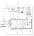
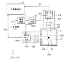
- FIG. 2 schematically illustrates a configuration example of the focused laser beam focused beam measurement apparatus according to the first embodiment of the present disclosure.
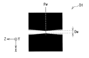
- FIG. 3 schematically shows an example of image data obtained when measuring a focused beam.
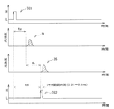
- FIG. 4 is a timing chart showing an example of an oscillation trigger, pulsed laser light, plasma emission light, and shutter trigger when measuring a focused beam.
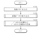
- FIG. 5 is a flowchart illustrating an example of a main processing operation by the measurement control unit.
- FIG. 6 shows an example of an image capture range when measuring a focused beam.
- FIG. 1 schematically illustrates an exemplary configuration of an exemplary LPP type EUV light generation system.
- FIG. 2 schematically illustrates a configuration example of the focused laser beam focused beam measurement apparatus according to the first embodiment of the present disclosure.
- FIG. 3 schematically shows an example of image data obtained when measuring a focused beam.
- FIG. 4 is a timing chart showing an example
- FIG. 7 is a flowchart illustrating an example of a subroutine for image capture processing.
- FIG. 8 is a flowchart illustrating an example of a subroutine of processing for calculating the beam waist position and the full width of the beam waist.
- FIG. 9 is an explanatory diagram illustrating an example of a calculation process of the beam waist position and the full width of the beam waist.
- FIG. 10 is a flowchart illustrating an example of a subroutine of a process for calculating the center position and the full width of the beam waist.
- FIG. 11 shows a modified example of shutter trigger generation.
- FIG. 12 schematically illustrates a configuration example in the YZ cross section of the focused beam measurement apparatus according to the second modification of the first embodiment.
- FIG. 12 schematically illustrates a configuration example in the YZ cross section of the focused beam measurement apparatus according to the second modification of the first embodiment.
- FIG. 13 schematically shows a configuration example in the YX cross section of the focused beam measurement apparatus according to the second modification.
- FIG. 14 is a flowchart illustrating an example of a processing operation of the measurement control unit in the focused beam measurement apparatus according to the second modification.
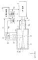
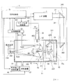
- FIG. 15 schematically shows a configuration example of an EUV light generation apparatus including a focused laser beam measuring apparatus for pulsed laser light.
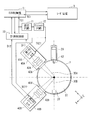
- FIG. 16 schematically shows a configuration example in the cross section along the line Y2-Y2 ′ of the EUV light generation apparatus including the focused beam measurement apparatus for pulsed laser light shown in FIG.
- FIG. 17 is a flowchart illustrating an example of a processing operation in the case of measuring a focused beam in an EUV light generation apparatus including a focused beam measuring apparatus for pulsed laser light.
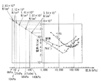
- FIG. 18 shows an example of the relationship between the pressure of the inert gas and the plasma generation.
- FIG. 19 shows an example of the hardware environment of the control unit.
- EUV Light Generation Device Including Pulsed Laser Light Condensing Beam Measurement Device] (Second Embodiment) 4.1 Configuration 4.2 Operation 4.2.1 Operation at EUV Light Generation 4.2.2 Operation at Focused Beam Measurement 4.3 Action [5. Others] 5.1 Relationship between inert gas pressure and plasma generation 5.2 Hardware environment of controller
- the present disclosure relates to an apparatus for measuring an image of plasma emission generated when pulse laser light is collected in an inert gas.
- FIG. 1 schematically shows a configuration of an exemplary LPP type EUV light generation system.
- the EUV light generation apparatus 1 may be used together with at least one laser apparatus 3.
- a system including the EUV light generation apparatus 1 and the laser apparatus 3 is referred to as an EUV light generation system 11.
- the EUV light generation apparatus 1 may include a chamber 2 and, for example, a target supply unit 26 as a target supply apparatus.
- the chamber 2 may be sealable.
- the target supply unit 26 may be attached so as to penetrate the wall of the chamber 2, for example.
- the material of the target substance supplied from the target supply unit 26 may include, but is not limited to, tin, terbium, gadolinium, lithium, xenon, or a combination of any two or more thereof.
- the wall of the chamber 2 may be provided with at least one through hole.
- a window 21 may be provided in the through hole.
- the pulse laser beam 32 output from the laser device 3 may pass through the window 21.
- an EUV collector mirror 23 having a spheroidal reflecting surface may be disposed.
- the EUV collector mirror 23 may have first and second focal points.
- On the surface of the EUV collector mirror 23, for example, a multilayer reflective film in which molybdenum and silicon are alternately laminated may be formed.
- the EUV collector mirror 23 is, for example, an intermediate collector whose first focus is located at or near the plasma generation region 25 and whose second focus is a desired focus position defined by the specifications of the exposure apparatus. It is preferable to be disposed at the point (IF) 292.
- a through hole 24 may be provided at the center of the EUV collector mirror 23, and the pulse laser beam 33 may pass through the through hole 24.
- the EUV light generation apparatus 1 can include an EUV light generation control unit 5. Further, the EUV light generation control unit 5 can include a target sensor 4 and the like. The target sensor 4 may detect at least one of the presence, trajectory, position, and speed of the target 27. The target sensor 4 may have an imaging function.
- the EUV light generation apparatus 1 may include a connection portion 29 that communicates the inside of the chamber 2 and the inside of the exposure apparatus 6.
- a wall 291 in which an aperture 293 is formed may be provided inside the connection portion 29.
- the wall 291 may be arranged such that its aperture 293 is located at the second focal position of the EUV collector mirror 23.
- the EUV light generation apparatus 1 may include a laser beam traveling direction control unit 34, a laser beam focusing mirror 22, a target recovery unit 28 for recovering the target 27, and the like.
- the laser beam traveling direction control unit 34 includes an optical element for defining the traveling direction of the laser beam and an actuator for adjusting the position, posture, and the like of the optical element in order to control the traveling direction of the laser beam. You may prepare.
- the pulsed laser beam 31 output from the laser device 3 passes through the window 21 as the pulsed laser beam 32 through the laser beam traveling direction control unit 34 and enters the chamber 2. May be.
- the pulse laser beam 32 may travel along the path of at least one laser beam into the chamber 2, be reflected by the laser beam collector mirror 22, and irradiate at least one target 27 as the pulse laser beam 33.
- the target supply unit 26 may be configured to output the target 27 toward the plasma generation region 25 inside the chamber 2.
- the target 27 may be irradiated with at least one pulse included in the pulse laser beam 33.
- the target 27 irradiated with the pulsed laser light is turned into plasma, and EUV light 251 can be emitted from the plasma together with the emitted light.
- the EUV light 251 may be reflected and collected by the EUV collector mirror 23.
- the EUV light 252 reflected by the EUV collector mirror 23 may be output to the exposure apparatus 6 through the intermediate condensing point 292.
- a single target 27 may be irradiated with a plurality of pulses included in the pulse laser beam 33.
- the EUV light generation controller 5 may be configured to control the entire EUV light generation system 11.
- the EUV light generation controller 5 may be configured to process image data of the target 27 imaged by the target sensor 4. Further, the EUV light generation controller 5 may be configured to control at least one of, for example, control of the timing at which the target 27 is output and control of the output direction of the target 27.
- the EUV light generation control unit 5 controls at least one of, for example, control of the oscillation timing of the laser device 3, control of the traveling direction of the pulse laser light 32, and control of the focusing position of the pulse laser light 33. It may be configured to do.
- the various controls described above are merely examples, and other controls may be added as necessary.
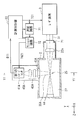
- FIG. 2 shows a configuration example of a focused beam measuring apparatus for pulsed laser light according to the first embodiment.
- FIG. 3 schematically shows an example of plasma emission image data as image data obtained when measuring a focused beam.
- the focused beam measurement device may be used together with the chamber 2 and the laser device 3.
- the focused beam measurement apparatus may include a camera 40, a measurement control unit 53, a delay circuit 71, and a one-shot circuit 72.
- the laser device 3 may include a laser oscillator that outputs the pulsed laser light 31 and a plurality of amplifiers that amplify the pulsed laser light 31.
- the laser oscillator and amplifier may include a CO 2 laser gas.
- the pulse laser beam 31 output from the laser device 3 may have a pulse energy of 50 mJ to 400 mJ and a pulse width of 10 ns to 25 ns.
- An oscillation trigger TG1 may be input to the laser oscillator.
- the chamber 2 may include a window 21, a laser focusing optical system 22a, a damper 44, and a window 43.
- the window 21 may be disposed on the wall of the chamber 2.
- the window 21, the laser focusing optical system 22a, and the damper 44 are arranged in this order along the traveling direction of the pulse laser beam 31 on the optical path of the pulse laser beam 31 output from the laser device 3. May be.
- the window 21 may be a diamond window through which CO 2 laser light is transmitted.
- the window 43 is formed on the wall of the chamber 2 so that an image of plasma emission generated by the beam waist of the pulse laser beam 31 by the laser focusing optical system 22a can be measured by the camera 40 from the off-axis of the optical path of the pulse laser beam 31. You may arrange.
- the window 43 may be arranged so that an image of plasma emission generated at the beam waist of the pulse laser beam 31 can be measured by the camera 40 from a direction substantially orthogonal to the optical path axis of the pulse laser beam 31.
- the beam waist of the pulse laser beam 31 is preferably set at the plasma generation region 25 or in the vicinity thereof.
- the laser condensing optical system 22 a may be a condensing lens that transmits the pulsed laser light 31.
- the laser focusing optical system 22a may be an optical system in which a plurality of lenses are combined. In that case, the lens material may be ZnSe.
- the laser focusing optical system 22a may be an optical system in which a plurality of mirrors are combined.
- the resolution of the laser focusing optical system 22a may be designed to be 70 ⁇ m to 300 ⁇ m.
- the chamber 2 may be filled with an inert gas 37 having a predetermined pressure in advance as a predetermined gas.
- the inert gas 37 may be Ar gas, for example, and the pressure may be a predetermined pressure in the range of 8 kPa to 140 kPa, for example.
- the pressure of the inert gas 37 may be adjusted according to the light intensity of the pulse laser beam 31.
- the measurement control unit 53 may output the signal of the oscillation trigger TG1 to the laser device 3 and the delay circuit 71.
- the delay circuit 71 may output a signal to the one-shot circuit 72.
- the one-shot circuit 72 may output a signal of the shutter trigger TG2 having a predetermined pulse width to the image sensor 41.
- the camera 40 may include a transfer optical system 42 and an image sensor 41.
- the transfer optical system 42 and the image sensor 41 may be arranged so that an image of plasma emission generated by the beam waist of the pulsed laser light 31 is formed on the light receiving surface of the image sensor 41.
- the transfer optical system 42 may be constituted by a resolving power combination lens capable of measuring the beam diameter of the focused beam of the pulsed laser light 31.
- the image sensor 41 may be a CCD (Charge Coupled Device) with an image intensifier.
- the image sensor 41 is an image sensor with a high-speed shutter, and may have a function of opening and closing the shutter for a predetermined time by a signal of the shutter trigger TG2.
- the image sensor 41 and the measurement control unit 53 may be connected so that the image data D1 captured by the image sensor 41 can be sent to the measurement control unit 53.
- the image data D1 may include plasma emission image data.
- the camera 40 is provided outside the optical path of the pulse laser beam 31 and has a function of capturing an image of plasma emission generated inside the chamber 2 by irradiating the inert gas 37 with the pulse laser beam 31, for example. You may have.
- the camera 40 may be disposed so as to face a direction substantially orthogonal to the optical path axis of the pulsed laser light 31.
- the plasma emission image captured by the camera 40 may be, for example, as illustrated in FIG.
- the measurement control unit 53 may have a function as a measurement unit that measures the condensing position and the condensing width of the pulsed laser light 31 based on the image data D1 obtained from the camera 40. For example, as shown in FIG. 3, the measurement control unit 53 may measure the condensing position of the condensing beam as the beam waist position Pw and the condensing width as the beam waist full width Dw based on the image data D1.
- FIG. 4 shows an example of the oscillation trigger TG1, the pulse laser beam 31, the plasma emission light 35, and the shutter trigger TG2 when measuring the condensed beam. With reference to the timing chart of FIG. 4 as appropriate, the overall operation when measuring the focused beam of the pulse laser beam 31 will be described.
- a pulse laser beam 31 having a wavelength of 10.6 ⁇ m can be output from the laser device 3.
- the pulsed laser light 31 can pass through the window 21 and enter the chamber 2.
- the pulse laser beam 31 can be condensed on the beam waist formed by this optical system by the laser condensing optical system 22a.
- the pulsed laser light 31 is condensed in an inert gas 37, and when a predetermined light intensity is exceeded, plasma is generated and plasma emission light 35 can be generated.
- the inert gas 37 may be, for example, Ar gas.
- the camera 40 can capture an image of plasma emission generated from this plasma.
- the image data D1 obtained by the camera 40 may be obtained as shown in FIG. 3, for example.
- the obtained image data D1 may be sent from the camera 40 to the measurement control unit 53.
- the measurement control unit 53 may calculate the beam waist full width Dw and the beam waist position Pw based on the image data D1.
- the measurement control unit 53 may synchronize the imaging timing by the camera 40 with the timing delayed from the output timing of the pulse laser beam 31 by the laser device 3.
- the measurement control unit 53 may control the delay circuit 71 and the one-shot circuit 72.
- the measurement control unit 53 may output the oscillation trigger TG1 as a pulse signal to the laser device 3 and the delay circuit 71.
- the laser apparatus 3 can output the pulse laser beam 31 after a predetermined delay time ta. Then, after tb time, the pulse laser beam 31 can reach the vicinity of the beam waist by the laser focusing optical system 22a.
- an electrical pulse signal can be output from the delay circuit 71 and input to the one-shot circuit 72 after a predetermined delay time td from the input of the pulse signal of the oscillation trigger TG1.
- a shutter trigger TG2 signal having a predetermined pulse width can be output to the camera 40.
- the predetermined delay time td is the time ta from when the oscillation trigger TG1 is input to the laser device 3 until the pulse laser beam 31 is output from the laser device 3, and the pulse laser beam 31 output from the laser device 3. May be set to be the sum of the time tb to reach the beam waist by the laser focusing optical system 22a.
- the plasma diffuses into the space immediately after the generation, and the light emitting region is enlarged accordingly.
- the elapsed time after the plasma generation and the opening / closing time of the shutter can affect the measurement accuracy in measuring the beam waist full width Dw and the beam waist position Pw.
- the plasma diffusion rate is 10 5 m / s, it can spread by 1 ⁇ m at 0.01 ns.
- the diameter of the beam waist is assumed to be 300 ⁇ m, for example, an accuracy of about 30 ⁇ m may be obtained as a measurement accuracy of 1/10 of the diameter.
- the delay circuit 71 may set the delay time to be td, and the shutter opening / closing time of the camera 40 may be opened and closed for 0.3 ns, for example. Furthermore, when a measurement accuracy of 1 ⁇ m is required, the shutter open time may be set to 0.01 ns. Further, when the diameter of the beam waist to be measured is assumed to be 1000 ⁇ m and a measurement accuracy of 100 ⁇ m is desired, the shutter open time may be set to 1 ns. The shutter open time may be defined by the pulse width of the shutter trigger TG2 signal output from the one-shot circuit 72.
- FIG. 5 shows an example of the main processing operation by the measurement control unit 53.
- the measurement control unit 53 may output the signal of the oscillation trigger TG1 to the laser device 3 and the delay circuit 71 (step S101).
- the measurement control unit 53 may perform processing for capturing the image data D1 by the camera 40 (step S102).
- the measurement control unit 53 may calculate the beam waist position Pw and the full width Dw of the beam waist based on the image data D1 (step S103).
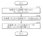
- FIG. 7 shows an example of the image data D1 acquisition process shown in FIG.
- the capturing process shown in FIG. 7 may be performed by the measurement control unit 53 as a subroutine of step S102 shown in FIG.
- FIG. 6 shows an example of the capture range of the image data D1.
- the measurement control unit 53 may cut out the data of the designated area 91 designated in advance from the image captured by the camera 40 as the image data D1. In this way, the data size of the image data to be captured is reduced, so that the processing time can be increased. However, when the position of the beam waist is greatly deviated from the designated area 91, the entire image size 90 may be captured as the image data D1.
- the image data D1 can be expressed as bitmap data, for example.
- Bitmap data may be data in which an image is divided into a number of pixels (pixels) in a grid pattern, and the light intensity at those pixels is represented by a numerical value.
- the upper right corner of the bitmap data image is the origin I (0, 0)
- the column number when the pixels are counted in the horizontal direction is represented by J
- the pixels are counted in the vertical direction.
- the line number of the hour may be represented by K.
- a pixel at a specific position is specified by a column number J and a row number K, and may be expressed as (K, J).
- the light intensity at the pixel (K, J) may be expressed as I (K, J) .
- the number of pixels of the image sensor 41 may be, for example, 512 columns ⁇ 512 rows.
- the value of J can be an integer in the range from 0 to 511
- the value of K can be an integer in the range from 0 to 511.
- the measurement control unit 53 may read a value indicating the image capture range, for example, when an image capture range as indicated by the designation area 91 in FIG. 6 is designated (step S111).
- the value indicating the capture range can be given by the minimum value (J min ) and the maximum value (J max ) of the column number J, and the minimum value (K min ) and the maximum value (K max ) of the row number K.
- the values of J min and J max are integers in the range of 0 ⁇ J min ⁇ J max ⁇ 511
- K min and K max May be an integer in the range of 0 ⁇ K min ⁇ K max ⁇ 511.
- the read values of J min and J max , K min and K max may always be constant values or may be changed depending on the situation.
- the measurement control unit 53 may read light intensity data at each pixel (K, J) within a predetermined capture range from the captured image data D1 (step S112). For example, in the example shown in FIG. 6, the pixel (K min , J min ), the pixel (K min , J max ), the pixel (K max , J max ), the pixel (K max , J min ), and these four The light intensity data I (K, J) in each of the pixels surrounded by the pixels may be read. By reading the light intensity data in the pixels within the limited range in this way, the subsequent processing can be speeded up.
- the measurement control unit 53 may perform a process of replacing the light intensity data in each pixel (K, J) with the data of the predefined array I (K, J) (step S113).
- the data I (K, J) of each light intensity of the image may be 8 to 10 bit data (for example, 0 to 1024).
- the measurement control unit 53 may end the subroutine according to this flowchart after performing the process of replacing the data with the array I (K, J).
- FIG. 8 shows an example of a process for calculating the beam waist position Pw and the beam waist full width Dw shown in FIG.
- the calculation process shown in FIG. 8 may be performed by the measurement control unit 53 as a subroutine of step S103 shown in FIG.
- FIG. 9 shows an example of a calculation process of the beam waist position Pw and the beam waist full width Dw.
- FIG. 9 shows an example of the light intensity distribution in the direction (J row) perpendicular to the Z axis in the image data D1.
- the measurement control unit 53 may set the column number J to J min (step S121). Next, as shown in FIG. 9, the measurement control unit 53 obtains the beam waist center position P and the beam waist full width D in the current column number J from the distribution of the light intensity data I (K, J) in the J column. You may calculate (step S122). The beam waist full width D may be calculated based on a position that is 1 / e 2 of the maximum value I max of the light intensity in the J column, as shown in FIG. Next, the measurement control unit 53 sets the calculated value X of the center position P to the data of the predefined array X (J) and the value of the beam waist full width D to the predefined array D. You may perform the process replaced with the data of (J) (step S123).
- the measurement control unit 53 may determine whether or not the current column number J has reached the maximum value J max of the J column in the image capture range as shown in FIG. 6 (step S124). .
- the measurement control unit 53 adds 1 to the current column number J, and updates the counter value of the column number J (step S125).
- the center position P of the beam waist and the full beam waist width D may be calculated again (step S122).
- the measurement control unit 53 When the maximum value J max is reached (step S124: Y), the measurement control unit 53 resets the column number J to J min (step S126), and then the value of the array D (J) is the array D. It may be determined whether or not the value is equal to or less than the value of (J + 1) (step S127). When the value of the array D (J) exceeds the value of the array D (J + 1) (step S127: N), the measurement control unit 53 adds 1 to the current column number J, and the counter of the column number J The value may be updated (step S128), and it may be determined again whether or not the value of the array D (J) is equal to or less than the value of the array D (J + 1) (step S127). In this way, the measurement control unit 53 may perform a process of comparing values in order to obtain the minimum value stored in the array D (J).
- the measurement control unit 53 determines that the value of the full beam waist width D in the current column number J is the minimum value. You may judge that. And the measurement control part 53 may perform the process which replaces the value of arrangement
- the measurement control unit 53 may perform processing for calculating the position Zw in the Z direction of the beam waist at the current column number J by the following equation (step S131).
- pz may be a pitch width per pixel in the Z direction in the image data D1.
- Zw J ⁇ pz ⁇ ⁇
- the measurement control unit 53 calculates the beam waist position Pw (x, z) by replacing the position Xw calculated as described above with x and the position Zw with z (step S132), and according to this flowchart.
- the subroutine may be terminated.
- (X, z) may be coordinates in the X direction and coordinates in the Z direction.
- FIG. 10 shows an example of a process for calculating the beam waist center position P and the beam waist full width D shown in FIG.
- the calculation process shown in FIG. 10 may be performed by the measurement control unit 53 as a subroutine of step S122 shown in FIG.
- the measurement control unit 53 may set the column number J to J min (step S141). Next, the measurement control unit 53 may obtain the maximum value I max from the light intensity distribution of the J row (step S142). Next, the measurement control unit 53 obtains a value of 1 / e 2 (I max / e 2 ) of the maximum value I max of the light intensity of the J row, and the position of the beam waist is expressed by, for example, FIG.
- the measurement control unit 53 may set the line number K to K min (step S144).
- the measurement control unit 5 may determine whether or not the light intensity I (K, J) at the row number K and the column number J is greater than or equal to the threshold value Ith (step S145). If it is not equal to or greater than the threshold value Ith (step S145: N), the measurement control unit 53 adds 1 to the current line number K, updates the counter value of the line number K (step S146), and again returns to the threshold value. It may be determined whether or not it is equal to or greater than Ith (step S145).
- the measurement control unit 53 may perform a process of calculating the beam waist upper end position X1 as shown in FIG. (Step S147).
- px may be a pitch width per pixel in the X direction in the image data D1.
- X1 K ⁇ px ⁇ ⁇
- the measurement control unit 53 may determine whether or not the light intensity I (K, J) at the row number K and the column number J is equal to or less than the threshold value Ith (step S148). If it is not less than or equal to the threshold value Ith (step S148: N), the measurement control unit 53 adds 1 to the current line number K, updates the counter value of the line number K (step S149), and again returns to the threshold value. It may be determined whether it is equal to or less than Ith (step S148).
- the measurement control unit 53 may perform processing for calculating the lower end position X2 of the beam waist as shown in FIG. (Step S150).
- px may be a pitch width per pixel in the X direction in the image data D1.
- X2 K ⁇ px ⁇ ⁇
- the measurement control unit 53 may perform the process of calculating the beam waist full width D as shown in FIG. 9 by the following formula (step S151).
- D X2-X1
- the measurement control unit 53 may perform a process of calculating the center position P of the beam waist as shown in FIG. 9 by the following formula (step S152), and the subroutine according to this flowchart may be terminated.
- X (X2 + X1) / 2
- plasma is generated by focusing the pulsed laser light 31 in the inert gas 37, and an image of the plasma emission is displayed on the high-speed shutter. Images can be taken with the camera 40 including the image. Thereby, as shown in FIG. 3, the propagation state of the condensed beam of the pulse laser beam 31 can be measured as an image.
- the beam waist full width Dw and the beam waist position Pw can be calculated from at least one pulse of the image data D1 of the pulse laser beam 31. According to this measurement, for example, there is no need to measure the beam profile at a plurality of positions along the optical path axis of the pulsed laser light 31 by moving the laser focusing optical system 22a or the image sensor 41 in the Z direction. The cross section of the beam waist need not be measured multiple times.
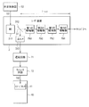
- the laser device 3 may include a master oscillator (MO) 311, a plurality of amplifiers, a beam splitter 312, and an optical sensor 313.
- the plurality of amplifiers may include, for example, a first amplifier PA1, a second amplifier PA2, a third amplifier PA3, and a fourth amplifier PA4.
- the master oscillator 311 may be a laser device that oscillates in the amplification wavelength region of the CO 2 laser.
- a laser oscillator including a quantum cascade laser and a Q switch may be used.
- the first amplifier PA1, the second amplifier PA2, the third amplifier PA3, and the fourth amplifier PA4 are amplifiers that are disposed on the optical path of the pulse laser beam 31 output from the master oscillator 311 and include CO 2 laser gas. There may be.
- the beam splitter 312 may be disposed on the optical path between the master oscillator 311 and the first amplifier PA1.
- a substrate that transmits the pulsed laser light 31 may be coated with a film that reflects part of the light output from the master oscillator 311 and transmits part of the light.
- the optical sensor 313 may detect the reflected light from the beam splitter 312.
- the optical sensor 313 is a pyroelectric sensor, and may include a circuit (not shown) that outputs an electric pulse signal.
- the pulse laser beam 31 can be output from the master oscillator 311.
- the pulsed laser light 31 is incident on the beam splitter 312, and part of the light is reflected and can be incident on the optical sensor 313.
- the pulse laser beam 31 transmitted through the beam splitter 312 can be amplified by passing through the first amplifier PA1 to the fourth amplifier PA4.
- the optical sensor 313 can output an electric pulse signal to the delay circuit 71 according to the timing at which the pulse laser beam 31 is incident.
- the delay circuit 71 can output to the one-shot circuit 72 an electrical pulse signal delayed by td from the input electrical pulse signal.
- the one-shot circuit 72 can output a shutter trigger TG2 signal having a predetermined pulse width to the image sensor 41 of the camera 40.
- the shutter trigger TG2 A signal can be generated.
- the opening / closing timing of the shutter of the image sensor 41 with respect to the timing of plasma emission generated by the beam waist of the pulse laser beam 31 can be controlled with high accuracy. This is particularly effective when there is jitter that cannot be ignored in the output timing of the pulse laser beam 31 output from the master oscillator 311 with respect to the oscillation trigger TG1.
- the beam splitter 312 is arranged on the optical path between the master oscillator 311 and the first amplifier PA1, but the beam splitter 312 is not limited to the configuration example of FIG. A splitter 312 may be arranged.
- the beam splitter 312 may be disposed on the optical path between the first amplifier PA1 and the second amplifier PA2, and the timing of the transmitted pulsed laser light 31 may be measured.
- the beam splitter 312 may be disposed on the optical path between the second amplifier PA2 and the third amplifier PA3.
- the beam splitter 312 may be disposed on the optical path between the third amplifier PA3 and the fourth amplifier PA4.
- the beam splitter 312 may be arranged on the optical path of the final output of the laser apparatus 3 or on the optical path between the laser apparatus 3 and the beam waist. The more the beam splitter 312 is arranged on the optical path closer to the beam waist, the shorter the delay time td of the delay circuit 71 is.
- FIGS. 12 and 13 illustrate a configuration example of the focused beam measurement apparatus according to the second modification of the first embodiment.
- FIG. 2 shows an example in which one camera 40 is provided as an imaging unit for measuring the condensed beam
- a configuration having two imaging units as shown in FIGS. 12 and 13 may be used.
- Each of the two imaging units may include a first camera 40A and a second camera 40B.
- 12 shows a configuration in the YZ section
- FIG. 13 shows a configuration in the YX section including the Y1-Y1 ′ line of FIG.
- the first camera 40A may have substantially the same configuration as the camera 40 of FIG.
- the first camera 40A may include a first transfer optical system 42A and a first image sensor 41A.
- the second camera 40B may include a second transfer optical system 42B and a second image sensor 41B.
- a window 43A may be provided on the wall of the chamber 2 corresponding to the position where the first camera 40A is disposed.
- a window 43B may be provided on the wall of the chamber 2 so as to correspond to the position where the second camera 40B is disposed.
- the first camera 40A may be arranged to face the first direction
- the second camera 40B may be arranged to face the second direction different from the first direction.
- the first direction may be the Y-axis direction
- the second direction may be the X-axis direction.
- the first camera 40 ⁇ / b> A and the second camera 40 ⁇ / b> B may be arranged so as to face in directions orthogonal to each other.
- the first camera 40 ⁇ / b> A and the second camera 40 ⁇ / b> B may be arranged so as to face each other in a direction orthogonal to the optical path of the pulse laser beam 31.
- the first camera 40A may capture an image of plasma emission from the first direction and output first image data D11 as first plasma emission image data.
- the second camera 40B may capture an image of plasma emission from the second direction and output the second image data D12 as the second plasma emission image data.
- a signal of the first shutter trigger TG21 having a predetermined pulse width is input to the first image sensor 41A
- a signal of the second shutter trigger TG22 having a predetermined pulse width is input to the second image sensor 41A.
- the first shutter trigger TG21 and the second shutter trigger TG22 may be obtained by branching substantially the same signal into two.
- the first image sensor 41 ⁇ / b> A and the measurement control unit 53 may be connected to send the first image data D ⁇ b> 11 captured by the first image sensor 41 ⁇ / b> A to the measurement control unit 53.
- the second image sensor 41B and the measurement control unit 53 may be connected so as to send the second image data D12 captured by the second image sensor 41B to the measurement control unit 53.
- the measurement control unit 53 measures the first condensing position and the first condensing width of the condensing beam of the pulsed laser light 31 based on the first image data D11 obtained from the first camera 40A. It may have a function.
- the first light collection position may be the first beam waist position Pxw, and the first light collection width may be the first beam waist full width Dxw.
- the measurement controller 53 also measures the second condensing position and the second condensing width of the condensing beam of the pulsed laser light 31 based on the second image data D12 obtained from the second camera 40B. It may have the function to do.
- the second condensing position may be the second beam waist position Pyw, and the second condensing width may be the second beam waist full width Dyw.
- the pulse laser beam 31 can be output from the laser apparatus 3.
- the pulsed laser light 31 can pass through the window 21 and enter the chamber 2.
- the pulse laser beam 31 can be condensed on the beam waist formed by this optical system by the laser condensing optical system 22a.
- the pulse laser beam 31 is condensed in an inert gas 37, and when a predetermined light intensity is exceeded, plasma is generated, and plasma emission light can be generated.
- the inert gas 37 may be, for example, Ar gas.
- the first camera 40A can capture an image of the first plasma emission light 35A observed from the first direction.
- the first image data D11 from the first camera 40A may be sent to the measurement control unit 53.
- the measurement control unit 53 may calculate the first beam waist position Pxw and the first beam waist full width Dxw from the first image data D11.
- the second camera 40B can capture an image of the second plasma emission light 35B observed from the second direction.
- the second image data D12 from the second camera 40B may be sent to the measurement control unit 53.
- the measurement control unit 53 may calculate the second beam waist position Pyw and the second beam waist full width Dyw from the second image data D12.
- FIG. 14 shows an example of the processing operation by the measurement control unit 53.
- the measurement control unit 53 may output the signal of the oscillation trigger TG1 to the laser device 3 and the delay circuit 71 (step S161).
- the measurement control unit 53 may perform a process of taking in the first image data D11 from the first camera 40A and the second image data D12 from the second camera 40B (step S162).
- the process of taking in the first image data D11 may be substantially the same as the process shown in FIG.
- the process of taking in the second image data D12 may be substantially the same as the process shown in FIG. 7 except that the coordinate system is replaced.
- the measurement control unit 53 may perform a process of replacing (Xw, Zw) with the first beam waist position Pxw (x, z) and replacing the full width Dw with the first beam waist full width Dxw ( Step S164).
- the beam waist full width and beam waist position can be measured for each of the X direction and the Y direction.
- the three-dimensional coordinate position (x, y, z) of the beam waist position can be measured.
- the beam waist full width and the beam waist position are measured differently in the X direction and the Y direction, it can mean that the curvature of the wavefront of the laser beam is different in the X direction and the Y direction.
- it can be determined that astigmatism has occurred in the pulsed laser beam 31 output from the laser device 3 and the laser focusing optical system 22a. You may evaluate the astigmatism of a condensing beam using this measurement result.
- any pulse laser device may be used.
- a solid-state pulse laser device may be used.
- a YAG laser device, a fiber laser device, or a titanium sapphire laser device may be used.
- Other laser devices that generate harmonics may be used.
- the lens is exemplified as the laser condensing optical system 22a, but it may be composed of a plurality of mirrors including a concave mirror. For example, a combination of an off-axis parabolic mirror and a plane mirror may be used.
- Ar gas is illustrated as an embodiment of the inert gas 37, an inert gas containing He gas, Kr gas, N 2 gas, or the like may be used. Further, a gas other than the inert gas 37 may be enclosed in the chamber 2. For example, hydrogen gas may be sealed. The gas sealed in the chamber 2 may be a mixed gas of a plurality of types of gases.
- the window 21 is exemplified by a diamond window, but may be a material that transmits CO 2 laser light, for example, ZnSe. However, when the output of the pulse laser beam 31 output from the laser device 3 is several hundred W or more, a diamond window is preferable.
- the measurement control unit 53 may set the delay time td of the delay circuit 71 and the pulse width of the one-shot circuit 72. Although the measurement control unit 53, the delay circuit 71, and the one-shot circuit 72 are described separately, the measurement control unit 53 may be configured to include the delay circuit 71 and the one-shot circuit 72.
- FIGS. 15 and 16 illustrate a configuration example of the EUV light generation apparatus according to the second embodiment.
- FIGS. 15 and 16 show an embodiment in which a measurement device similar to the focused beam measurement device shown in FIGS. 12 and 13 is mounted on the EUV light generation device.
- 15 shows a configuration in a cross section including the Z axis
- FIG. 16 shows a configuration in a cross section taken along line Y2-Y2 ′ of FIG.
- the EUV light generation apparatus may be used together with at least one laser apparatus 3.
- the EUV light generation apparatus includes a chamber 2, an EUV light generation control unit 5, a laser light traveling direction control unit 34, an exhaust device 47, an inert gas supply device 46, a delay circuit 71, and a one-shot circuit 72. And may be included.
- the EUV light generation controller 5 may include an EUV controller 51, a target generation controller 52, and a measurement controller 53.
- the laser beam traveling direction control unit 34 may be arranged so that the pulsed laser beam 31 output from the laser device 3 enters the chamber 2.
- the laser device 3 may be a CO 2 laser device that outputs a pulse laser beam 31 having a wavelength of 10.6 ⁇ m, a pulse width of 10 to 50 ns, a frequency of 50 mJ to 400 mJ, and a repetition frequency of 50 k to 100 kHz.
- the inert gas supply device 46 and the exhaust device 47 may be connected to the chamber 2 via a gas pipe.
- the chamber 2 may include a target supply unit 26, a laser focusing optical system 22a, a plate 82, and an XYZ axis stage 84. Further, the chamber 2 may include an EUV collector mirror 23, a mirror holder 81, a damper 44, a window 21, a target recovery unit 28, and a gate valve 294.
- a first camera 40A may be attached to the chamber 2 via a window 43A.
- a second camera 40B may also be attached to the chamber 2 via a window 43B.
- the target supply unit 26 may be arranged so that the target 27 output from the nozzle 62 reaches the plasma generation region 25 in a droplet shape.
- the target collection unit 28 may be installed on an extension line of the trajectory of the droplet-like target 27.
- the window 21 may be sealed and fixed to the inner wall of the chamber 2.
- the laser condensing optical system 22 a may include a plate 83, a holder 223, a holder 224, an off-axis parabolic mirror 221, and a flat mirror 222.
- the off-axis parabolic mirror 221 may be held on the plate 83 by the holder 223.
- the plane mirror 222 may be held on the plate 83 by the holder 224. The positions and postures of these mirrors may be maintained so that the pulsed laser light 31 reflected by the off-axis paraboloid mirror 221 and the plane mirror 222 is condensed in the plasma generation region 25.
- the damper 44 may be disposed on the optical path of the pulsed laser light 31 condensed by the laser condensing optical system 22a by a holder of the damper 44 (not shown).
- the XYZ axis stage 84 may be arranged so that the beam waist formed by the laser focusing optical system 22a moves in the X axis direction, the Y axis direction, and the Z axis direction.
- Each of the first camera 40A and the second camera 40B is arranged so as to face orthogonal directions as in the configuration example shown in FIG. You may arrange
- An image of plasma emission may be taken from the first direction by the first camera 40A and output as the first image data D11.
- an image of plasma emission may be taken from the second direction by the second camera 40B and output as the second image data D12.
- the first direction may be, for example, the Y-axis direction
- the second direction may be, for example, the X-axis direction.
- the plate 82 may be fixed to the wall inside the chamber 2.
- the EUV collector mirror 23 may be a spheroid mirror centered on the Z axis.
- the first focal point of the spheroid may be fixed to the plate 82 via the mirror holder 81 so as to substantially coincide with the plasma generation region 25.
- the EUV control unit 51 outputs output signals to the inert gas supply device 46, the exhaust device 47, the laser device 3, the target generation control unit 52, the measurement control unit 53, and the gate valve 294, respectively. Good.
- the signal of the oscillation trigger TG1 of the measurement control unit 53 may be input to the laser device 3 via the EUV control unit 51.
- the gate valve 294 may be opened and closed by a signal from the EUV control unit 51 to communicate or isolate the inside of the chamber 2 and the inside of the exposure apparatus 6.
- the laser beam traveling direction control unit 34 may be composed of two plane mirrors 341 and 342.
- the reflection surfaces of the plane mirrors 341 and 342, the plane mirror 222, and the off-axis paraboloidal mirror 221 may be coated with a film that highly reflects the pulsed laser light 31.
- the reflective surface of the EUV collector mirror 23 may be coated with a Mo / Si multilayer film.
- the EUV control unit 51 may transmit a droplet generation signal to the target supply unit 26 via the target generation control unit 52.
- a droplet-shaped target 27 can be generated from the nozzle 62 of the target supply unit 26.
- the EUV control unit 51 controls the laser device 3 so that the droplet-shaped target 27 is irradiated with the pulsed laser light 31 when the generated droplet-shaped target 27 reaches the plasma generation region 25.
- the oscillation trigger TG1 may be output.
- the pulse laser beam 31 can be output from the laser device 3.
- the pulse laser beam 31 can be highly reflected by the plane mirrors 341 and 342 of the laser beam traveling direction control unit 34 and can enter the window 21.
- the pulsed laser light 31 that has passed through the window 21 can be focused on the plasma generation region 25 by the off-axis parabolic mirror 221 and the flat mirror 222.
- the droplet-shaped target 27 that has reached the plasma generation region 25 is irradiated with the pulsed laser light 31 to be turned into plasma and generate EUV light.
- the EUV light may be condensed at an intermediate condensing point (IF) 292 by the EUV condensing mirror 23 and output to the exposure apparatus 6.
- IF intermediate condensing point
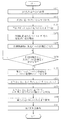
- FIG. 17 shows an example of the processing operation of the EUV control unit 51 when measuring the condensed beam of the pulsed laser light 31.
- the EUV control unit 51 may perform the following operation when it is necessary to measure the condensed beam.
- the processing operation by the EUV control unit 51 shown in FIG. 17 may be executed at the start-up or maintenance of the EUV light generation apparatus. In addition, when it is necessary to confirm the condensing state of the pulse laser beam 31, you may perform suitably.
- the EUV controller 51 may confirm that the EUV light generation operation is stopped (step S171). At this time, the EUV control unit 51 may confirm through the target generation control unit 52 that the generation of the droplet-shaped target 27 is stopped. Further, the EUV control unit 51 may confirm that the output of the pulsed laser light 31 is stopped in the laser device 3. At this time, the EUV control unit 51 may close the gate valve 294.
- the EUV control unit 51 may control the exhaust device 47 so that when the buffer gas or the like is present in the chamber 2, the exhaust may be performed until the pressure becomes close to a vacuum (step S172).
- the buffer gas may contain hydrogen gas, for example.
- the pressure close to vacuum may be, for example, 1 hPa or less.
- the EUV control unit 51 may control the inert gas supply device 46 to supply an inert gas 37 such as Ar gas, for example, until a predetermined pressure for generating plasma is reached (step S173).
- the EUV control unit 51 may start accepting the oscillation trigger TG1 (step S174). Thereby, when the signal of the oscillation trigger TG1 of the pulse laser beam 31 is output from the measurement control unit 53 to the EUV control unit 51, the signal of the oscillation trigger TG1 is input to the laser device 3 via the EUV control unit 51. It may be in a state.
- the EUV controller 51 may output a measurement signal to the measurement controller 53 so that the measurement process shown in the flowchart of FIG. 14 is executed in the measurement controller 53 (step S175).
- the measurement control part 53 may perform the measurement process shown by the flowchart of FIG.
- the measurement control unit 53 may transmit a signal indicating that the measurement process is completed to the EUV control unit 51.
- the EUV control unit 51 may determine whether or not a signal indicating that the measurement of the focused beam has been completed is received from the measurement control unit 53 (step S176).
- the EUV control unit 51 receives the beam waist full width Dw and the beam waist position Pw (from the measurement control unit 53). x, y, z) may be received (step S177).
- the EUV control unit 51 calculates the difference ⁇ P ( ⁇ x, ⁇ ) between the beam waist position Pw (x, y, z) and the coordinates Pt (xt, yt, zt) of the desired plasma generation region as in the following equation.
- ⁇ y, ⁇ z may be calculated (step S178).
- ⁇ P ( ⁇ x, ⁇ y, ⁇ z) Pw (x, y, z) ⁇ Pt (xt, yt, zt)
- the EUV controller 51 drives the XYZ axis stage 84 based on ⁇ P ( ⁇ x, ⁇ y, ⁇ z) so that the beam waist formed by the laser focusing optical system 22a is at an appropriate position. It is also possible (step S179).
- the EUV control unit 51 may control the exhaust device 47 to exhaust the inert gas 37 such as Ar gas present in the chamber 2 until the pressure is close to vacuum (step S180).
- the EUV control unit 51 may prepare for generating EUV light (step S181).
- the EUV control unit 51 may prepare for generating the droplet-shaped target 27 via the target generation control unit 52.
- the EUV controller 51 may make preparations for supplying a buffer gas into the chamber 2.
- the EUV control unit 51 may open the gate valve 294.
- the beam waist of the pulsed laser light 31 that is actually focused on the droplet-shaped target 27 by mounting the focused beam measurement device on the EUV light generation device The full width Dw and the beam waist position Pw can be measured with high accuracy. Further, the condensing position by the laser condensing optical system 22a can be controlled with high accuracy so that the beam waist position of the pulsed laser light 31 is an appropriate position with respect to the position of the desired plasma generation region 25. As a result, the condensing state of the pulse laser light may be stabilized, and stable EUV light generation may be possible.
- FIG. 18 shows an example of the relationship between inert gas pressure and plasma generation.
- the horizontal axis represents pressure (kpa), and the vertical axis represents electric field (V / cm).
- FIG. 18 shows an example of argon (Ar) gas, helium (He) gas, and nitrogen (N 2 ) gas as examples of the inert gas.
- Ar argon
- He helium
- N 2 nitrogen
- the light intensity In is expressed by the following formula.
- Dw is the full width of the beam waist of the pulse laser beam
- ⁇ is the pulse width
- E is the pulse energy.
- Dw may be 300 ⁇ m
- ⁇ may be 20 ns
- E may be 50 mJ, 100 mJ, 200 mJ, 300 mJ, or 400 mJ, for example.
- In E / ( ⁇ ⁇ ⁇ (Dw / 2) 2 )
- FIG. 19 is a block diagram illustrating an example hardware environment in which various aspects of the disclosed subject matter may be implemented.
- the exemplary hardware environment 100 of FIG. 19 includes a processing unit 1000, a storage unit 1005, a user interface 1010, a parallel I / O controller 1020, a serial I / O controller 1030, A / D, D / A.
- the converter 1040 may be included, the configuration of the hardware environment 100 is not limited to this.
- the processing unit 1000 may include a central processing unit (CPU) 1001, a memory 1002, a timer 1003, and an image processing unit (GPU) 1004.
- the memory 1002 may include random access memory (RAM) and read only memory (ROM).
- the CPU 1001 may be any commercially available processor. A dual microprocessor or other multiprocessor architecture may be used as the CPU 1001.
- FIG. 19 may be interconnected to perform the processes described in this disclosure.
- the processing unit 1000 may read and execute a program stored in the storage unit 1005. Further, the processing unit 1000 may read data from the storage unit 1005 together with the program. Further, the processing unit 1000 may write data to the storage unit 1005.
- the CPU 1001 may execute a program read from the storage unit 1005.
- the memory 1002 may be a work area for temporarily storing programs executed by the CPU 1001 and data used for the operation of the CPU 1001.
- the timer 1003 may measure the time interval and output the measurement result to the CPU 1001 according to the execution of the program.
- the GPU 1004 may process the image data according to a program read from the storage unit 1005 and output the processing result to the CPU 1001.
- the parallel I / O controller 1020 is a parallel I / O device that can communicate with the processing unit 1000, such as the delay circuit 71, the laser device 3, the image sensor 41, the first image sensor 41A, and the second image sensor 41B. They may be connected and may control communication between the processing unit 1000 and their parallel I / O devices.
- the serial I / O controller 1030 may be connected to a serial I / O device that can communicate with the processing unit 1000, such as the one-shot circuit 72, and performs communication between the processing unit 1000 and these serial I / O devices. You may control.
- the A / D and D / A converter 1040 may be connected to analog devices such as a temperature sensor, a pressure sensor, and various vacuum gauge sensors via an analog port, and communication between the processing unit 1000 and these analog devices. Or A / D and D / A conversion of communication contents may be performed.
- the user interface 1010 may display the progress of the program executed by the processing unit 1000 to the operator so that the operator can instruct the processing unit 1000 to stop the program or execute the interrupt routine.
- the exemplary hardware environment 100 may be applied to the configurations of the EUV light generation control unit 5, the laser light traveling direction control unit 34, the EUV control unit 51, the target generation control unit 52, and the measurement control unit 53 in the present disclosure.
- controllers may be implemented in a distributed computing environment, i.e., an environment where tasks are performed by processing units connected via a communications network.
- the EUV light generation control unit 5, the laser beam traveling direction control unit 34, the EUV control unit 51, the target generation control unit 52, and the measurement control unit 53 are connected via a communication network such as Ethernet (registered trademark) or the Internet. They may be connected to each other.
- program modules may be stored in both local and remote memory storage devices.
- CPU Central processing unit
- Memory 1003 ...
- Timer 1004 Image processing unit (GPU), 1005 Storage unit, 1010 User interface, 1020 Parallel I / O controller, 1030 Serial I / O controller, 1040 A / D, D / A converter, D1 Image data ( Plasma emission image data), D11 ... first image data (first plasma emission image data), D12 ... second image data (second plasma emission image data), td ... delay time, TG1 ... oscillation trigger, TG21 ... first shutter trigger, TG22 ... second Shutter trigger, Pw ... beam waist position (condensing position), Dw ... full beam waist width (condensing width), PA1 ... first amplifier, PA2 ... second amplifier, PA3 ... third amplifier, PA4 ... fourth Amplifier.
- D1 Image data Plasma emission image data
- D11 ... first image data first plasma emission image data
- D12 ... second image data second plasma emission image data
- td ... delay time TG1 ... oscillation trigger
- TG21 ... first shutter trigger TG22
Landscapes
- Physics & Mathematics (AREA)
- Engineering & Computer Science (AREA)
- Optics & Photonics (AREA)
- Plasma & Fusion (AREA)
- General Physics & Mathematics (AREA)
- Health & Medical Sciences (AREA)
- Environmental & Geological Engineering (AREA)
- Epidemiology (AREA)
- Public Health (AREA)
- Spectroscopy & Molecular Physics (AREA)
- General Engineering & Computer Science (AREA)
- High Energy & Nuclear Physics (AREA)
- Exposure And Positioning Against Photoresist Photosensitive Materials (AREA)
- X-Ray Techniques (AREA)
Abstract
La présente invention concerne un dispositif de génération de lumière ultraviolette extrême, comprenant : une chambre renfermant un gaz prescrit ; un système optique de convergence de lumière qui est disposé dans un chemin de lumière pour lumière laser à impulsions sortie à l'aide d'un dispositif laser, et qui collecte la lumière laser à impulsions ; et une unité d'imagerie, qui est disposée à l'extérieur de l'axe du chemin optique de la lumière laser à impulsions, et qui permet d'imager l'image de lumière générée à partir du plasma généré à l'intérieur de la chambre par la lumière laser à impulsions collectée par le système optique de convergence de lumière irradiant le gaz prescrit.
Priority Applications (2)
| Application Number | Priority Date | Filing Date | Title |
|---|---|---|---|
| JP2015506552A JP6381520B2 (ja) | 2013-03-21 | 2013-12-10 | 極端紫外光生成装置及びパルスレーザ光の集光ビーム計測装置 |
| US14/824,270 US9510434B2 (en) | 2013-03-21 | 2015-08-12 | Extreme ultraviolet light generating apparatus, method of generating extreme ultraviolet light, concentrated pulsed laser light beam measuring apparatus, and method of measuring concentrated pulsed laser light beam |
Applications Claiming Priority (2)
| Application Number | Priority Date | Filing Date | Title |
|---|---|---|---|
| JP2013057994 | 2013-03-21 | ||
| JP2013-057994 | 2013-03-21 |
Related Child Applications (1)
| Application Number | Title | Priority Date | Filing Date |
|---|---|---|---|
| US14/824,270 Continuation US9510434B2 (en) | 2013-03-21 | 2015-08-12 | Extreme ultraviolet light generating apparatus, method of generating extreme ultraviolet light, concentrated pulsed laser light beam measuring apparatus, and method of measuring concentrated pulsed laser light beam |
Publications (1)
| Publication Number | Publication Date |
|---|---|
| WO2014147901A1 true WO2014147901A1 (fr) | 2014-09-25 |
Family
ID=51579612
Family Applications (1)
| Application Number | Title | Priority Date | Filing Date |
|---|---|---|---|
| PCT/JP2013/083048 Ceased WO2014147901A1 (fr) | 2013-03-21 | 2013-12-10 | Dispositif de génération de lumière ultraviolette extrême, procédé de génération de lumière ultraviolette extrême, dispositif de mesure de faisceau de lumière convergente pour lumière laser à impulsions, et procédé de mesure de faisceau de lumière convergente |
Country Status (3)
| Country | Link |
|---|---|
| US (1) | US9510434B2 (fr) |
| JP (1) | JP6381520B2 (fr) |
| WO (1) | WO2014147901A1 (fr) |
Cited By (6)
| Publication number | Priority date | Publication date | Assignee | Title |
|---|---|---|---|---|
| JP2018513989A (ja) * | 2015-03-03 | 2018-05-31 | エーエスエムエル ネザーランズ ビー.ブイ. | 放射センサ装置 |
| WO2018123035A1 (fr) * | 2016-12-28 | 2018-07-05 | ギガフォトン株式会社 | Appareil photographique cible et appareil de génération de lumière ultraviolette extrême |
| CN108475027A (zh) * | 2016-01-18 | 2018-08-31 | Asml荷兰有限公司 | 射束测量系统、光刻系统和方法 |
| WO2019163029A1 (fr) * | 2018-02-21 | 2019-08-29 | ギガフォトン株式会社 | Système laser |
| JP2025032299A (ja) * | 2019-08-30 | 2025-03-11 | ティーエーイー テクノロジーズ, インコーポレイテッド | ビーム位置監視およびビーム撮像のためのシステム、デバイス、ならびに方法 |
| JP2025039831A (ja) * | 2022-08-31 | 2025-03-21 | レーザーテック株式会社 | 位置検出装置及び位置検出方法 |
Families Citing this family (1)
| Publication number | Priority date | Publication date | Assignee | Title |
|---|---|---|---|---|
| WO2014192872A1 (fr) * | 2013-05-31 | 2014-12-04 | ギガフォトン株式会社 | Système de génération d'ultraviolet extrême |
Citations (7)
| Publication number | Priority date | Publication date | Assignee | Title |
|---|---|---|---|---|
| JP2004303725A (ja) * | 2003-03-28 | 2004-10-28 | Xtreme Technologies Gmbh | プラズマの放射発散を安定化するための装置 |
| JP2007109451A (ja) * | 2005-10-12 | 2007-04-26 | Komatsu Ltd | 極端紫外光源装置の初期アライメント方法 |
| JP2008103151A (ja) * | 2006-10-18 | 2008-05-01 | Komatsu Ltd | 極端紫外光源装置 |
| JP2010103499A (ja) * | 2008-09-29 | 2010-05-06 | Komatsu Ltd | 極端紫外光源装置および極端紫外光生成方法 |
| WO2011013779A1 (fr) * | 2009-07-29 | 2011-02-03 | 株式会社小松製作所 | Source de lumière ultraviolette extrême, son procédé de commande, et support denregistrement sur lequel est enregistré un programme pour ledit procédé |
| JP2011216851A (ja) * | 2010-03-18 | 2011-10-27 | Komatsu Ltd | チャンバ装置および極端紫外光生成装置 |
| JP2012199512A (ja) * | 2011-03-10 | 2012-10-18 | Gigaphoton Inc | 極端紫外光生成装置及び極端紫外光生成方法 |
Family Cites Families (8)
| Publication number | Priority date | Publication date | Assignee | Title |
|---|---|---|---|---|
| US5017012A (en) | 1989-08-04 | 1991-05-21 | Chapman Instruments, Inc. | Viewing system for surface profiler |
| US7989786B2 (en) * | 2006-03-31 | 2011-08-02 | Energetiq Technology, Inc. | Laser-driven light source |
| WO2010137625A1 (fr) * | 2009-05-27 | 2010-12-02 | ギガフォトン株式会社 | Dispositif de sortie de cible et dispositif à source de lumière dans l'ultraviolet extrême |
| JP5625414B2 (ja) * | 2010-03-18 | 2014-11-19 | 株式会社Ihi | X線発生方法 |
| JP2013065804A (ja) * | 2010-12-20 | 2013-04-11 | Gigaphoton Inc | レーザ装置およびそれを備える極端紫外光生成システム |
| JP2012178534A (ja) | 2011-02-02 | 2012-09-13 | Gigaphoton Inc | 光学システムおよびそれを用いた極端紫外光生成システム |
| US8633459B2 (en) | 2011-03-02 | 2014-01-21 | Cymer, Llc | Systems and methods for optics cleaning in an EUV light source |
| US9000405B2 (en) * | 2013-03-15 | 2015-04-07 | Asml Netherlands B.V. | Beam position control for an extreme ultraviolet light source |
-
2013
- 2013-12-10 WO PCT/JP2013/083048 patent/WO2014147901A1/fr not_active Ceased
- 2013-12-10 JP JP2015506552A patent/JP6381520B2/ja active Active
-
2015
- 2015-08-12 US US14/824,270 patent/US9510434B2/en active Active
Patent Citations (7)
| Publication number | Priority date | Publication date | Assignee | Title |
|---|---|---|---|---|
| JP2004303725A (ja) * | 2003-03-28 | 2004-10-28 | Xtreme Technologies Gmbh | プラズマの放射発散を安定化するための装置 |
| JP2007109451A (ja) * | 2005-10-12 | 2007-04-26 | Komatsu Ltd | 極端紫外光源装置の初期アライメント方法 |
| JP2008103151A (ja) * | 2006-10-18 | 2008-05-01 | Komatsu Ltd | 極端紫外光源装置 |
| JP2010103499A (ja) * | 2008-09-29 | 2010-05-06 | Komatsu Ltd | 極端紫外光源装置および極端紫外光生成方法 |
| WO2011013779A1 (fr) * | 2009-07-29 | 2011-02-03 | 株式会社小松製作所 | Source de lumière ultraviolette extrême, son procédé de commande, et support denregistrement sur lequel est enregistré un programme pour ledit procédé |
| JP2011216851A (ja) * | 2010-03-18 | 2011-10-27 | Komatsu Ltd | チャンバ装置および極端紫外光生成装置 |
| JP2012199512A (ja) * | 2011-03-10 | 2012-10-18 | Gigaphoton Inc | 極端紫外光生成装置及び極端紫外光生成方法 |
Cited By (13)
| Publication number | Priority date | Publication date | Assignee | Title |
|---|---|---|---|---|
| JP2018513989A (ja) * | 2015-03-03 | 2018-05-31 | エーエスエムエル ネザーランズ ビー.ブイ. | 放射センサ装置 |
| US10900829B2 (en) | 2015-03-03 | 2021-01-26 | Asml Netherlands B.V. | Radiation sensor apparatus |
| CN108475027A (zh) * | 2016-01-18 | 2018-08-31 | Asml荷兰有限公司 | 射束测量系统、光刻系统和方法 |
| WO2018123035A1 (fr) * | 2016-12-28 | 2018-07-05 | ギガフォトン株式会社 | Appareil photographique cible et appareil de génération de lumière ultraviolette extrême |
| US10976664B2 (en) | 2016-12-28 | 2021-04-13 | Gigaphoton Inc. | Target image capturing device and extreme ultraviolet light generation device |
| JPWO2018123035A1 (ja) * | 2016-12-28 | 2019-10-31 | ギガフォトン株式会社 | ターゲット撮影装置及び極端紫外光生成装置 |
| JPWO2019163029A1 (ja) * | 2018-02-21 | 2021-03-11 | ギガフォトン株式会社 | レーザシステム |
| WO2019163029A1 (fr) * | 2018-02-21 | 2019-08-29 | ギガフォトン株式会社 | Système laser |
| US11350515B2 (en) | 2018-02-21 | 2022-05-31 | Gigaphoton Inc. | Laser system |
| JP7123323B2 (ja) | 2018-02-21 | 2022-08-23 | ギガフォトン株式会社 | レーザシステム |
| JP2025032299A (ja) * | 2019-08-30 | 2025-03-11 | ティーエーイー テクノロジーズ, インコーポレイテッド | ビーム位置監視およびビーム撮像のためのシステム、デバイス、ならびに方法 |
| JP2025039831A (ja) * | 2022-08-31 | 2025-03-21 | レーザーテック株式会社 | 位置検出装置及び位置検出方法 |
| JP7802218B2 (ja) | 2022-08-31 | 2026-01-19 | レーザーテック株式会社 | 位置検出装置及び位置検出方法 |
Also Published As
| Publication number | Publication date |
|---|---|
| US20150351211A1 (en) | 2015-12-03 |
| JPWO2014147901A1 (ja) | 2017-02-16 |
| JP6381520B2 (ja) | 2018-08-29 |
| US9510434B2 (en) | 2016-11-29 |
Similar Documents
| Publication | Publication Date | Title |
|---|---|---|
| JP6381520B2 (ja) | 極端紫外光生成装置及びパルスレーザ光の集光ビーム計測装置 | |
| US8653491B2 (en) | System, method and apparatus for aligning and synchronizing target material for optimum extreme ultraviolet light output | |
| US12085585B2 (en) | Particle image velocimetry of extreme ultraviolet lithography systems | |
| JP6168797B2 (ja) | 極端紫外光生成装置 | |
| US10674591B2 (en) | Target expansion rate control in an extreme ultraviolet light source | |
| JP6689255B2 (ja) | ターゲット撮像装置、極端紫外光生成装置及び極端紫外光生成システム | |
| JP2022008595A (ja) | 極端紫外光源におけるターゲット膨張率制御 | |
| JP6715259B2 (ja) | 極端紫外光生成装置 | |
| US9713240B2 (en) | Stabilizing EUV light power in an extreme ultraviolet light source | |
| CN102185250A (zh) | 一种产生飞秒级时间分辨的x射线源的装置及方法 | |
| KR20220022472A (ko) | 레이저 집속 모듈 | |
| JP6799583B2 (ja) | 極端紫外光生成装置及び極端紫外光の重心位置の制御方法 | |
| JP2018525666A (ja) | Lpp euv光源におけるソースレーザの発射を制御するためのシステム及び方法 | |
| CN109041393A (zh) | 一种超快硬x射线源的产生装置及方法 | |
| WO2018203370A1 (fr) | Dispositif d'alimentation cible, générateur de lumière uv extrême et procédé d'alimentation cible | |
| JP6434404B2 (ja) | 極端紫外光生成システム | |
| US20230010985A1 (en) | Source material delivery system, euv radiation system, lithographic apparatus, and methods thereof | |
| US12282262B2 (en) | Method for controlling extreme ultraviolet light | |
| JPWO2016079810A1 (ja) | 極端紫外光生成装置及び極端紫外光の生成方法 | |
| WO2020183550A1 (fr) | Dispositif de piégeage d'étain, dispositif de génération de lumière ultraviolette extrême, et procédé de fabrication d'un dispositif électronique | |
| JP7780948B2 (ja) | 極端紫外光生成装置及び電子デバイスの製造方法 | |
| US11043784B2 (en) | Laser apparatus and EUV light generation system | |
| NL2012718A (en) | Radiation systems and associated methods. |
Legal Events
| Date | Code | Title | Description |
|---|---|---|---|
| 121 | Ep: the epo has been informed by wipo that ep was designated in this application |
Ref document number: 13879102 Country of ref document: EP Kind code of ref document: A1 |
|
| ENP | Entry into the national phase |
Ref document number: 2015506552 Country of ref document: JP Kind code of ref document: A |
|
| NENP | Non-entry into the national phase |
Ref country code: DE |
|
| 122 | Ep: pct application non-entry in european phase |
Ref document number: 13879102 Country of ref document: EP Kind code of ref document: A1 |