WO2014148162A1 - Procédé de positionnement et dispositif de positionnement - Google Patents
Procédé de positionnement et dispositif de positionnement Download PDFInfo
- Publication number
- WO2014148162A1 WO2014148162A1 PCT/JP2014/053374 JP2014053374W WO2014148162A1 WO 2014148162 A1 WO2014148162 A1 WO 2014148162A1 JP 2014053374 W JP2014053374 W JP 2014053374W WO 2014148162 A1 WO2014148162 A1 WO 2014148162A1
- Authority
- WO
- WIPO (PCT)
- Prior art keywords
- positioning
- laminated
- separator
- moving
- mea
- Prior art date
- Legal status (The legal status is an assumption and is not a legal conclusion. Google has not performed a legal analysis and makes no representation as to the accuracy of the status listed.)
- Ceased
Links
Images







Classifications
-
- B—PERFORMING OPERATIONS; TRANSPORTING
- B32—LAYERED PRODUCTS
- B32B—LAYERED PRODUCTS, i.e. PRODUCTS BUILT-UP OF STRATA OF FLAT OR NON-FLAT, e.g. CELLULAR OR HONEYCOMB, FORM
- B32B38/00—Ancillary operations in connection with laminating processes
- B32B38/18—Handling of layers or the laminate
- B32B38/1825—Handling of layers or the laminate characterised by the control or constructional features of devices for tensioning, stretching or registration
- B32B38/1833—Positioning, e.g. registration or centering
- B32B38/1841—Positioning, e.g. registration or centering during laying up
-
- B—PERFORMING OPERATIONS; TRANSPORTING
- B32—LAYERED PRODUCTS
- B32B—LAYERED PRODUCTS, i.e. PRODUCTS BUILT-UP OF STRATA OF FLAT OR NON-FLAT, e.g. CELLULAR OR HONEYCOMB, FORM
- B32B2457/00—Electrical equipment
- B32B2457/18—Fuel cells
-
- B—PERFORMING OPERATIONS; TRANSPORTING
- B32—LAYERED PRODUCTS
- B32B—LAYERED PRODUCTS, i.e. PRODUCTS BUILT-UP OF STRATA OF FLAT OR NON-FLAT, e.g. CELLULAR OR HONEYCOMB, FORM
- B32B37/00—Methods or apparatus for laminating, e.g. by curing or by ultrasonic bonding
- B32B37/0046—Methods or apparatus for laminating, e.g. by curing or by ultrasonic bonding characterised by constructional aspects of the apparatus
-
- H—ELECTRICITY
- H01—ELECTRIC ELEMENTS
- H01M—PROCESSES OR MEANS, e.g. BATTERIES, FOR THE DIRECT CONVERSION OF CHEMICAL ENERGY INTO ELECTRICAL ENERGY
- H01M8/00—Fuel cells; Manufacture thereof
- H01M8/02—Details
- H01M8/0202—Collectors; Separators, e.g. bipolar separators; Interconnectors
- H01M8/0247—Collectors; Separators, e.g. bipolar separators; Interconnectors characterised by the form
-
- H—ELECTRICITY
- H01—ELECTRIC ELEMENTS
- H01M—PROCESSES OR MEANS, e.g. BATTERIES, FOR THE DIRECT CONVERSION OF CHEMICAL ENERGY INTO ELECTRICAL ENERGY
- H01M8/00—Fuel cells; Manufacture thereof
- H01M8/10—Fuel cells with solid electrolytes
- H01M8/1004—Fuel cells with solid electrolytes characterised by membrane-electrode assemblies [MEA]
-
- Y—GENERAL TAGGING OF NEW TECHNOLOGICAL DEVELOPMENTS; GENERAL TAGGING OF CROSS-SECTIONAL TECHNOLOGIES SPANNING OVER SEVERAL SECTIONS OF THE IPC; TECHNICAL SUBJECTS COVERED BY FORMER USPC CROSS-REFERENCE ART COLLECTIONS [XRACs] AND DIGESTS
- Y02—TECHNOLOGIES OR APPLICATIONS FOR MITIGATION OR ADAPTATION AGAINST CLIMATE CHANGE
- Y02E—REDUCTION OF GREENHOUSE GAS [GHG] EMISSIONS, RELATED TO ENERGY GENERATION, TRANSMISSION OR DISTRIBUTION
- Y02E60/00—Enabling technologies; Technologies with a potential or indirect contribution to GHG emissions mitigation
- Y02E60/30—Hydrogen technology
- Y02E60/50—Fuel cells
Definitions
- the present invention relates to a positioning method and a positioning device that embodies the positioning method.
- a fuel cell is configured by alternately laminating separators and membrane electrode assemblies (MEAs). Since the fuel cell can obtain a high output according to the number of stacks of separators and MEAs, it is desirable to increase the number of stacks. On the other hand, if the positions of the separator and MEA to be laminated are relatively shifted, for example, the reference positions of the through holes for anode gas, cathode gas, and cooling water provided in the separator and MEA respectively do not match, The original battery performance cannot be achieved.
- the shapes of the first laminated member (for example, the separator) and the second laminated member (for example, MEA) that are alternately laminated are different from each other due to specifications and manufacturing tolerances, they are accurately obtained. A technique capable of positioning has been demanded.
- the present invention has been made to solve the above-described problems, and can position each of the first laminated member and the second laminated member with high accuracy even when the shapes of the first laminated member and the second laminated member are different from each other due to specifications and manufacturing tolerances.
- An object is to provide a positioning method and a positioning device that embodies the positioning method.
- the positioning method has a positioning step.
- the first laminated member and the second laminated member are independently moved in the direction intersecting the laminating direction, so that they are independently brought into contact with positioning positioning members arranged along the laminating direction.
- the first laminated member and the second laminated member are positioned relative to each other.
- the positioning device that achieves the above object positions at least a first laminated member and a second laminated member that are each formed in a plate shape and are laminated in a plane crossing the lamination direction.
- the positioning device includes a positioning member, a moving member, and a control unit.
- the positioning member is disposed in a direction intersecting with the stacking direction of the first stacked member and the second stacked member to be stacked.
- the moving member moves the first laminated member and the second laminated member, which are plurally laminated, independently.
- the control unit controls the operation of the moving member, moves the first laminated member and the second laminated member by the moving member, and abuts the positioning member independently.
- FIG. 3 is a top view showing the configuration shown in FIG. 2 from above in the first embodiment. It is a figure which shows the principal part of the state before positioning a separator and MEA mutually independently using the positioning device which concerns on 1st Embodiment. It is a figure which shows the principal part of the state after positioning a separator and MEA mutually independently using the positioning device which concerns on 1st Embodiment.
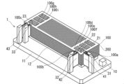
- FIG. 1 is a perspective view schematically showing a state in which a plurality of separators 100 and MEAs 200 are alternately stacked on a positioning device 1 that embodies a positioning method.
- FIG. 2 is a perspective view showing a state in which the separator 100 and the MEA 200 are positioned independently of each other using the positioning device 1.
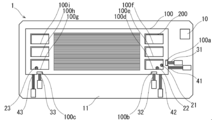
- FIG. 3 is a top view showing the configuration shown in FIG. 2 from above.
- FIG. 4 is a diagram showing a main part in a state before the separator 100 and the MEA 200 are positioned independently of each other using the positioning device 1.
- FIG. 4A is a perspective view showing the main part
- FIG. 4B is a top view showing the main part.
- FIG. 5 is a diagram illustrating a main part in a state after the separator 100 and the MEA 200 are positioned independently of each other using the positioning device 1.
- FIG. 5A is a perspective view showing the main part
- FIG. 5B is a top view showing the main part.
- FIG. 6 is a cross-sectional view showing a state in which the MEA 200 is positioned with respect to the longitudinal direction using the positioning device 1.
- FIG. 7 is a cross-sectional view showing a state in which the plurality of separators 100 are positioned with respect to the longitudinal direction using the positioning device 1.
- FIG. 8 is a diagram showing a main part in a state after the separator 100 and the MEA 200 are positioned independently of each other using the positioning device 2.
- FIG. 8A is a perspective view showing the main part
- FIG. 8B is a top view showing the main part.
- FIG. 9 is a diagram illustrating a main part in a state after the separator 100 and the MEA 200 are positioned independently of each other using the positioning device 3.
- FIG. 9A is a perspective view showing the main part
- FIG. 9B is a top view showing the main part.
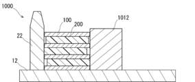
- FIG. 14 is a diagram illustrating a main part in a state after the separator 100 and the MEA 200 are positioned by using the positioning device 1000 according to the comparative example.
- FIG. 14A is a perspective view showing the main part
- FIG. 14B is a top view showing the main part.
- FIG. 15 is a cross-sectional view showing a main part in a state after the separator 100 and the MEA 200 are positioned using the positioning device 1000 according to the proportionality.
- FIG. 15 is a sectional view taken along line 15-15 in FIG. 14 (b).
- FIGS. 1 to 9 the numbers of separators 100 and MEAs 200 shown in FIGS. Actually, the separator 100 and the MEA 200 are positioned with respect to the positioning device 1 in a state where the separator 100 and the MEA 200 are alternately stacked over several tens to several thousand layers, for example.
- FIG. 2 as an example, a state in which a total of ten separators 100 are alternately arranged with a total of nine MEAs 200 is illustrated.
- FIG. 4 to FIG. 9, FIG. 14, and FIG. 15 the number of stacked layers of the separator 100 and the MEA 200 is shown as being reduced from the actual number.
- FIGS. 4, 5, 8, 9, and 14, one MEA 200 is disposed between the two separators 100.
- FIGS. 6, 7, and 15 show a configuration in which a total of four separators 100 are alternately arranged with a total of three MEAs 200.
- the size of the manifold hole and the outer shape is changed to the separator 100 and the MEA 200. It is very different.
- the positioning method according to the first embodiment can be applied even when the design dimensions of the manifold hole and the outer shape are the same.
- first laminated member (separator 100) and the second laminated member (MEA 200) that perform positioning using the positioning device 1 will be described with reference to FIG.
- the first laminated member corresponds to, for example, a separator 100 used for a fuel cell.
- the separator 100 is formed in a long plate shape.
- the separator 100 includes a through hole corresponding to a cathode gas supply port 100d, a cooling fluid supply port 100e, and an anode gas supply port 100f at one end in the longitudinal direction.
- the separator 100 includes through holes corresponding to the anode gas discharge port 100g, the cooling fluid discharge port 100h, and the cathode gas discharge port 100i at the other end in the longitudinal direction.
- Positioning members 21 and 22, which will be described later, are inserted into the separator 100, for example, the cathode gas supply port 100d.
- a positioning member 23 to be described later is inserted into, for example, the anode gas discharge port 100g of the separator 100.
- the separator 100 has rectangular cutouts 100a, 100b, and 100c formed on the outer peripheral edge thereof.
- the notch 100a is formed from the outer peripheral edge of the separator 100 in the short direction toward the cathode gas supply port 100d.
- the notch 100a is for avoiding interference with the second moving member 31 described later.
- the notch 100b is formed from the outer peripheral edge in the longitudinal direction of the separator 100 toward the cathode gas supply port 100d.
- the notch 100b is for avoiding interference with the second moving member 32 described later.
- the notch 100c is formed from the outer peripheral edge of the separator 100 in the longitudinal direction toward the anode gas discharge port 100g.
- the notch 100c is for avoiding interference with the second moving member 33 described later.
- the second laminated member corresponds to, for example, a membrane electrode assembly (MEA 200) used for a fuel cell.
- the MEA 200 is formed in a long plate shape.
- the MEA 200 includes a through hole corresponding to a cathode gas supply port 200d, a cooling fluid supply port 200e, and an anode gas supply port 200f at one end in the longitudinal direction.
- the MEA 200 is provided with through holes corresponding to the anode gas discharge port 200g, the cooling fluid discharge port 200h, and the cathode gas discharge port 200i at the other end in the longitudinal direction.
- the MEA 200 inserts positioning members 21 and 22 described later into the cathode gas supply port 200d. Similarly, a positioning member 23 described later is inserted through the anode gas discharge port 200g of the MEA 200.
- the positioning device 1 includes, for example, a controller 10, a support base 11, a mounting base 12, positioning members 21 to 23, second moving members 31 to 33, and first moving members 41 to 43. Each component of the positioning device 1 will be described in order.
- the controller 10 corresponds to a control unit.
- the controller 10 is a ROM (Read Only Memory) that stores the control program for the positioning device 1, a CPU (Central Processing Unit) that controls the operation of the positioning device 1 based on the control program, and various data under control. RAM (Random Access Memory) to be included.
- the controller 10 moves the separator 100 and the MEA 200 by the moving members (the second moving members 31 to 33 and the first moving members 41 to 43) and makes them contact with the positioning members 21 to 23 independently.
- the support table 11 is a table on which the mounting table 12, the second moving members 31 to 33, and the first moving members 41 to 43 are disposed.
- the support base 11 is made of metal, for example, and is formed in a long shape.
- the mounting table 12 is a table for mounting the separator 100 and the MEA 200 in an alternately stacked state.
- the mounting table 12 is disposed on the upper side of the support table 11.
- the mounting table 12 is made of metal, for example, and is formed in a long shape smaller than the support table 11. Positioning members 21 to 23, which will be described later, are disposed on the mounting table 12.
- the positioning members 21 to 23 contact the separator 100 and the MEA 200 to position the separator 100 and the MEA 200.
- the positioning members 21 to 23 are made of metal and are formed in a cylindrical shape.
- the positioning members 21 to 23 are disposed on the mounting table 12. Specifically, the positioning member 21 is disposed inside the cathode gas supply port 100d provided in the separator 100 mounted on the mounting table 12 so as to face the notch 100a.
- the positioning member 22 is disposed inside the cathode gas supply port 100d provided in the separator 100 mounted on the mounting table 12 so as to face the notch 100b.
- the positioning member 23 is disposed inside the anode gas discharge port 100g provided in the separator 100 mounted on the mounting table 12 so as to face the notch 100c.
- the positioning members 22 and 23 position the separator 100 and the MEA 200 along the short direction.
- the positioning member 21 positions the separator 100 and the MEA 200 along the longitudinal direction.
- the second moving members 31, 32, and 33 press the MEA 200 while avoiding interference with the separator 100 by the notches 100a, 100b, and 100c, respectively.
- the second moving members 31, 32, and 33 have a configuration in which a protruding portion is linearly expanded and contracted using a uniaxial electric stage or compressed gas supplied from the outside.
- the second moving member 31 is disposed on the support table 11 in a state of being adjacent to the mounting table 12 along the short direction of the separator 100 and the MEA 200 so as to face the positioning member 21.
- the second moving member 32 is disposed on the support table 11 in a state of being adjacent to the mounting table 12 along the longitudinal direction of the separator 100 and the MEA 200 so as to face the positioning member 22.
- the second moving member 33 is disposed on the support table 11 in a state of being adjacent to the mounting table 12 along the longitudinal direction of the separator 100 and the MEA 200 so as to face the positioning member 23.
- the first moving members 41, 42 and 43 press the separator 100.
- the first moving members 41, 42, and 43 have a configuration in which the protruding portion is linearly expanded and contracted using a uniaxial electric stage or compressed gas supplied from the outside, like the second moving member 31 and the like.
- the first moving member 41 is disposed on the support base 11 adjacent to the second moving member 31 along the short direction of the separator 100 and the MEA 200 so as to face the positioning member 21.
- the first moving member 42 is disposed on the support 11 adjacent to the second moving member 32 along the longitudinal direction of the separator 100 and the MEA 200 so as to face the positioning member 22.
- the first moving member 43 is disposed on the support base 11 adjacent to the second moving member 33 along the longitudinal direction of the separator 100 and the MEA 200 so as to face the positioning member 23.
- a pair of handling hands 301 and 302 are used for transporting the separator 100 and the MEA 200. As shown in FIG. 1, the longitudinal end of the separator 100 is grasped by the handling hand 302 while the longitudinal end of the separator 100 is grasped by the handling hand 301.
- the pair of handling hands 301 and 302 can be moved to arbitrary positions in the horizontal and vertical directions by a three-axis moving stage (not shown).
- the separator 100 and the MEA 200 are brought into a state in which the positional deviation shown in FIG. FIG. 5 corresponds to FIG. 2 and FIG. 3 and shows a state in which the positioning of the separator 100 and the MEA 200 is completed.
- the positioning members 22 and 23 are simultaneously operated to position the separator 100 and the MEA 200 along the short direction. That is, the positioning members 22 and 23 are pressed against the outer peripheral edges of the separator 100 and the MEA 200 in the longitudinal direction.
- the positioning member 21 is operated to position the separator 100 and the MEA 200 along the longitudinal direction. That is, the positioning member 21 is pressed against the outer peripheral edge of the separator 100 and the MEA 200 in the short direction.
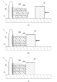
- FIG. 6A shows a state before starting positioning of the plurality of MEAs 200, corresponding to a cross section taken along line 6 (a) -6 (a) in FIG. It is sectional drawing which shows a state typically.
- FIG. 6A the positions of the three MEAs 200 are shifted from each other.
- FIG. 6B is a cross-sectional view schematically showing the way in which a plurality of MEAs 200 are being positioned.
- FIG. 6C shows a state in which the positioning of the plurality of MEAs 200 has been completed, and corresponds to the cross section taken along line 6 (c) -6 (c) in FIG. It is sectional drawing shown typically.
- the three MEAs 200 are positioned at the reference positions by contacting the positioning member 22.
- FIG. 7A shows a state before starting positioning of the plurality of separators 100, corresponding to the cross section taken along line 7 (a) -7 (a) in FIG. 4B. It is sectional drawing which shows the state in in.
- FIG. 7A the positions of the four separators 100 are shifted. However, of the four separators 100, the lowermost separator 100 is in contact with the positioning member 22 and already positioned.
- FIG. 7B is a cross-sectional view schematically showing the way in which the plurality of separators 100 are being positioned.
- FIG. 7B the three separators 100 excluding the lowermost one separator 100 are pressed against the first moving member 42, so that the relative displacement is corrected.
- FIG. 7C shows a state in which the positioning of the plurality of separators 100 is completed, corresponding to the cross section taken along line 7 (c) -7 (c) in FIG. It is sectional drawing which shows this typically.
- the three separators 100 are brought into contact with the positioning member 22, so that the four separators 100 including the lowermost one separator 100 that has been in contact with the positioning member 22 from the beginning. Each is positioned at a reference position.
- a positioning device 2 as shown in FIG. 8 may be configured.
- the positioning device 2 newly uses long positioning members 51 and 52 instead of the columnar positioning members 21 and 22 used in the above-described positioning device 1 shown in FIG.
- the positioning member 51 has its surface along the longitudinal direction opposed to the second moving member 31 and the first moving member 41 in a state orthogonal thereto.
- the positioning member 52 has its surface along the longitudinal direction opposed to the second moving member 32 and the first moving member 42 in a state of being orthogonal.
- the configuration corresponding to the positioning member 52 is arranged at both ends in the longitudinal direction of the separator 100 as in FIG. 3.
- the positioning member 51 and the second moving member 31 that presses the MEA 200 are respectively arranged on the same straight line along the moving direction of the second moving member 31. Can do.
- the positioning member 51 and the first moving member 41 that presses the separator 100 can be arranged on the same straight line along the moving direction of the first moving member 41.
- a positioning device 3 as shown in FIG. 9 may be configured.
- the positioning device 3 uses a rectangular parallelepiped positioning member 61 in place of the columnar positioning members 21 and 22 used in the above-described positioning device 1 shown in FIG.
- the positioning member 51 has one side surface opposed to the second moving member 31 and the first moving member 41 in a state of being orthogonal.
- the positioning member 52 is opposed to the second moving member 32 and the first moving member 42 in the state where the other surface orthogonal to one surface of the positioning member 52 is orthogonal.
- the configuration corresponding to the positioning member 61 is disposed at both ends in the longitudinal direction of the separator 100 as in FIG.
- the corners of the positioning member 61 are chamfered to avoid interference with the separator 100 and the MEA 200.
- the positioning device 1000 according to the proportional structure has a configuration as shown in FIGS.
- the positioning device 1000 does not necessarily contact all the separators 100 and the MEAs 200 with the positioning members 21 and 22 after positioning the separators 100 and the MEAs 200 alternately stacked. Unlike the positioning devices 1 to 3 described above, the relative positioning device 1000 moves the separator 100 and the MEA 200 together using the moving members 1011 and 1012 as shown in FIG. 22 respectively.
- FIG. 15 for example, due to manufacturing tolerances, when the size of the separator 100 is larger than the size of the MEA 200, when all the separators 100 come into contact with the positioning members 22, some of the MEA 200. Is not in contact with the positioning member 22.
- the positioning apparatus 1000 according to the proportionality when the positioning apparatus 1000 according to the proportionality is used, a part of the MEA 200 positioned between the positioning member 22 and the moving member 1012 is blocked by the separator 100 having a size larger than that of the MEA 200, so that the positioning member 22 Cannot touch.
- the positioning operation may be completed in a state where some of the MEAs 200 are not in contact with the positioning member 22.
- the positioning method at least the separator 100 and the MEA 200, which are each formed in a plate shape and stacked, are positioned in a plane intersecting the stacking direction.
- the positioning method has a positioning step. In the positioning step, the separator 100 and the MEA 200 are independently moved in the direction intersecting the stacking direction, so that they are brought into contact with the positioning positioning members 21 to 23 arranged along the stacking direction. The separator 100 and the MEA 200 are positioned relative to each other.
- Positioning devices 1 to 3 each position at least the separator 100 and the MEA 200, which are each formed in a plate shape and stacked, in a plane intersecting the stacking direction.
- the positioning devices 1 to 3 include positioning members 21 to 23, a moving member, and a control unit 10.
- the positioning members 21 to 23 are arranged in a direction crossing the stacking direction of the separators 100 and MEAs 200 to be stacked.
- the moving member moves a plurality of stacked separators 100 and MEAs 200 independently of each other.
- the control unit 10 controls the operation of the moving member, and moves the separator 100 and the MEA 200 by the moving member so as to contact each of the positioning members 21 to 23 independently.
- the separator 100 and the MEA 200 are moved independently of each other to be brought into contact with the positioning members 21 to 23 and positioned relative to each other. Therefore, for example, even when the shapes of the separator 100 and the MEA 200 are different from each other due to specifications and manufacturing tolerances, the separator 100 and the MEA 200 can be accurately positioned with respect to the positioning members 21 to 23, respectively.
- the positioning method and the positioning apparatuses 1 to 3 when the separator 100 and the MEA 200 having different shapes are stacked, the mutual positional deviation can be minimized.
- the positioning method and the positioning devices 1 to 3 can prevent an increase in the size of the stack and a decrease in battery performance due to the stacking variation of the separator 100 and the MEA 200.
- the MEA 200 including the cathode gas supply port 200d may be used.
- the inner surfaces of the first through hole and the second through hole are brought into contact with the positioning members 51 and the like inserted through the first through hole and the second through hole, respectively.
- the inner surfaces of the first through hole and the second through hole are brought into contact with the positioning members 61 inserted through the first through hole and the second through hole, respectively.
- the positioning member 52 and the moving member are moved to the moving member (the first moving member 42 and the moving member 42). You may arrange
- a plurality of positioning members 21 to 23 and a plurality of moving members may be used.
- the separator 100 and the MEA 200 are aligned with one direction in a plane intersecting the stacking direction. They are positioned with respect to each other in two directions perpendicular to the direction.
- the separator 100 and the MEA 200 can be positioned with respect to each other in two directions within a plane intersecting the stacking direction.
- the positioning method includes first moving members 41 to 43 that move the separator 100 independently, and second moving members 31 to 33 that move the MEA 200 independently, A separator 100 having notches 100a to 100c with a part of the outer periphery notched may be used.
- the first moving members 41 to 43 press or pull portions other than the notches 100a to 100c on the outer periphery of the separator 100.
- the second moving members 31 to 33 press or pull the region of the outer periphery of the MEA 200 that overlaps the notches 100a to 100c of the separator 100.
- the second moving members 31 to 33 are positioned when the separator 100 and the MEA 200 are positioned by a very simple configuration using the cutout portions 100a to 100c in which a part of the outer periphery of the separator 100 is cut. Does not interfere with the separator 100. This is particularly suitable when the laminated member is made of a thin material such as the separator 100 or the MEA 200.
- FIG. 10 is a diagram showing a main part in a state after the separator 100 and the MEA 200 are positioned independently of each other by using the positioning device 4.
- FIG. 10A is a top view showing the main part.
- FIG. 10B is a cross-sectional view showing the main part along the line 10 (b) -10 (b) in FIG. 10A.
- the manifold hole and the size of the outer shape are greatly different between the separator 100 and the MEA 200.
- the positioning method according to the second embodiment can be applied even when the design dimensions of the manifold hole and the outer shape are the same.
- the positioning device 4 according to the second embodiment uses a configuration in which a moving member 72 having a first protrusion 72a and a second protrusion 72b arranged in steps in a direction along the stacking direction of the separator 100 and the MEA 200 is used. This is different from the configuration of the positioning devices 1 to 3 according to the first embodiment described above.
- the moving members 71 and 72 have the same configuration. Although omitted in FIG. 10A, the configuration corresponding to the moving member 72 is disposed at both ends in the longitudinal direction of the separator 100 as in FIG. As shown in FIG. 10 (b), for example, the moving member 72 is made of, for example, hard plastics, and is formed in a rectangular shape having uneven projections on the contact surface with the separator 100 and the MEA 200. ing. Specifically, the moving member 72 includes a first protrusion 72a and a second protrusion 72b that have different protrusion lengths along the moving direction.
- the moving member 72 presses the separator 100 with the first protrusion 72 a and presses the MEA 200 with the second protrusion 72 b, thereby separating the separator 100 against the positioning member 22. And MEA 200 are brought into contact with each other. Since the moving member 72 sets the protrusion lengths of the first protrusions 72a and the second protrusions 72b individually according to the dimensions of the separator 100 and the separator 100, respectively, Even if the lengths of the MEAs 200 are different, they can be pressed and brought into contact with the positioning member 22.
- the positioning device 4 that embodies the positioning method according to the second embodiment described above, in addition to the functions and effects according to the first embodiment described above, the following functions and effects are further exhibited.
- the positioning device 4 uses a moving member 72 provided with a first protrusion 72a and a second protrusion 72b having different protrusion lengths along the stacking direction of the separator 100 and the MEA 200, respectively.
- the separator 100 is pressed by the first protrusion 72a, and the MEA 200 is pressed by the second protrusion 72b.
- the separator 100 and the MEA 200 are accurately positioned with respect to the positioning member with a very simple configuration using the first protrusion and the second protrusion disposed in different steps. be able to.
- the laminated member is not limited to the separator 100 and the MEA 200, and is particularly suitable when the layer thickness is sufficiently thick. Furthermore, it is suitable when the design dimensions of the separator 100 and the MEA 200 are different.
- FIG. 11 is a diagram showing a main part in a state after the separator 100 and the MEA 200 are positioned independently of each other using the positioning device 5.
- FIG. 11A is a top view showing the main part.
- FIG. 11B is a cross-sectional view showing the main part along the line 11 (b) -10 (b) in FIG. 11A.
- the manifold hole and the size of the outer shape are greatly different between the separator 100 and the MEA 200.
- the positioning method according to the third embodiment can be applied even when the design dimensions of the manifold hole and the outer shape are the same.
- the configuration of the positioning device 5 according to the third embodiment is different from the configuration of the positioning devices 1 to 4 according to the first and second embodiments described above, in that the configuration using the moving member 81 provided with an elastically deformable elastic body is used.
- the moving members 81 and 83 have the same configuration and are mounted on the holding members 82 and 84, respectively. Although omitted in FIG. 11A, the configuration corresponding to the moving member 83, the holding member 84, and the like are arranged at both ends in the longitudinal direction of the separator 100 as in FIG. 3.
- the moving members 81 and 83 correspond to elastic bodies that can be elastically deformed.
- the moving members 81 and 83 are made of a rubber material, for example, and are formed in a rectangular shape.
- the holding members 82 and 84 are made of, for example, hard plastics and are formed in a rectangular shape.
- the moving member 83 is contracted in a state where the separator 100 and the MEA 200 are in contact with the positioning member 22 respectively.
- the first contact portion 83 a of the moving member 83 that contacts the separator 100 is more contracted than the second contact portion 83 b of the moving member 83 that contacts the MEA 200.
- the positioning member 22 is used as a reference, since the separator 100 is longer than the MEA 200 in FIG. 11, the first contact portion 83a is relatively contracted relative to the second contact portion 83b.
- the movable member 83 can be elastically deformed, even if the separators 100 and the MEAs 200 alternately stacked are different in length, they can be pressed and brought into contact with the positioning member 22. Furthermore, since the moving member 83 can be elastically deformed, for example, even if the lengths of the plurality of separators 100 are different from each other, each separator 100 can be pressed and brought into contact with the positioning member 22.
- the positioning device 5 that embodies the positioning method according to the third embodiment described above, in addition to the functions and effects according to the first and second embodiments described above, the following functions and effects are further exhibited.
- the positioning device 5 uses a moving member 81 provided with an elastic body that can be elastically deformed at least in a portion that presses the separator 100 and the MEA 200.
- the separator 100 and the MEA 200 can be accurately positioned with respect to the positioning member with a very simple configuration using an elastic body that is easily stretchable, such as rubber.
- the laminated member is not limited to the separator 100 and the MEA 200, and is particularly suitable when the layer thickness is sufficiently thick and is made of a hard material that does not adhere to the elastic body.
- the elastic body may be configured to be provided at the tip of each of the moving members 72 including the first protrusions 72a and the second protrusions 72b disposed in the above-described steps.
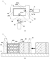
- FIG. 12 is a diagram showing a main part in a state after the separator 100 and the MEA 200 are positioned independently of each other by using the positioning device 6.
- FIG. 12A is a top view showing the main part.
- FIG. 12B is a cross-sectional view showing the main part along the line 12 (b) -12 (b) in FIG.
- FIG. 13 is a flowchart showing a control for positioning the separator 100 and the MEA 200 independently of each other using the positioning device 6.
- the manifold hole and the size of the outer shape are greatly different between the separator 100 and the MEA 200.
- the positioning method according to the fourth embodiment can be applied even when the design dimensions of the manifold hole and the outer shape are the same.
- the configuration of the positioning device 6 according to the fourth embodiment is different from the configuration of the positioning devices 1-5 according to the first to third embodiments described above in that the positioning device 6 is moved while detecting the state of the separator 100 and the MEA 200.
- the configuration of the positioning device 6 will be described with reference to FIG.
- the positioning device 6 corresponds to a configuration in which a detection member is added to the positioning device 5 described above.
- the detection member is controlled by the controller 10.
- the positioning device 6 has first detection members 91 and 92 embedded in holding members 82 and 84, respectively.
- the first detection members 91 and 92 may be disposed adjacent to the holding members 82 and 84.
- the first detection members 91 and 92 correspond to pressure sensors.
- the first detection members 91 and 92 detect the reaction force applied to the moving members 81 and 83 that pressed the separator 100 or the MEA 200.
- the positioning device 6 has second detection members 93 and 94 embedded in the positioning members 21 and 22, respectively.
- the second detection members 93 and 94 may be disposed adjacent to the positioning members 21 and 22.
- the second detection members 93 and 94 correspond to pressure sensors.
- the second detection members 93 and 94 detect the pressure applied to the positioning members 21 and 22 pressed from the separator 100 or the MEA 200.
- the structures corresponding to the first detection member 92 and the second detection member 94 are respectively disposed at both ends in the longitudinal direction of the separator 100 as in FIG.
- a plurality of separators 100 and MEAs 200 are alternately stacked on the positioning device 6 (S101 in FIG. 13).
- the moving member 83 and the like are moved so as to approach the separator 100 and the MEA 200 in the longitudinal direction (S102 in FIG. 13).
- the first detection member 92 or the like embedded in the holding member 84 or the like the pressure generated when the moving member 83 or the like comes into contact with the separator 100 and the MEA 200 is detected (S103 in FIG. 13).
- a control circuit (not shown) connected to the first detection member 92 or the like, it is determined whether or not the pressure applied to the first detection member 92 or the like is within a predetermined range.
- the process returns to S102. If the pressure is above the specified range (high pressure), the process proceeds to S105. If the pressure is within the specified range, the process returns to S106. move on. For example, when the separator 100 or the like is in contact with and interferes with some member, the pressure exceeds the specified pressure (S104 in FIG. 13). Here, when it progresses to S105 from S104, the separator 100 and MEA200 are replaced
- the separator 100 and the MEA 200 are pressed using the moving member 83 or the like, and the separator 100 and the MEA 200 are moved so as to approach the positioning member 22 or the like (S106 in FIG. 13).
- the second detection member 94 or the like embedded in the positioning member 22 or the like, the pressure generated when the separator 100 and the MEA 200 contact the positioning member 22 or the like is detected (S107 in FIG. 13).
- a control circuit (not shown) connected to the second detection member 94 or the like, it is determined whether or not the pressure applied to the second detection member 94 or the like is equal to or higher than a predetermined value.
- S109 to S114 correspond to S102 to S108, and the separator 100 and the MEA 200 are positioned in the direction along the longitudinal direction (S109 to S114 in FIG. 13).
- the separator 100 and the MEA 200 that have been positioned are held by a holding member (not shown) (S115 in FIG. 13).
- the positioning device 6 that embodies the positioning method according to the fourth embodiment described above, in addition to the functions and effects according to the first to third embodiments described above, the following functions and effects are further exhibited.
- the positioning device 6 uses, for example, a first detection member 92 that is embedded or adjacent to the holding member 84 connected to the moving member 83 and detects the pressure applied to the moving member 83.
- the first detection member 92 detects the pressure applied to the moving member 83 when the moving member comes into contact with the separator 100 or the MEA 200.
- the positioning device 6 configured in this manner, for example, in a state where the separator 100 or the MEA 200 interferes with other members and the movement is inhibited, the separator 100 or the MEA 200 is excessively pressed by the moving member and deformed. Can be prevented. Thus, even if a defect occurs during positioning of the separator 100 and the MEA 200, it can be appropriately handled.
- the positioning device 6 may be configured to use, for example, a second detection member 94 that is embedded in or adjacent to the positioning member 22 and detects the pressure applied to the positioning member 22.
- the second detection member 94 detects the pressure applied to the positioning member 22 when the positioning member 22 contacts the separator 100 or the MEA 200.
- the positioning device 6 configured as described above, it is possible to confirm whether or not the positioning of the separator 100 or the MEA 200 is completed. Therefore, it is possible to prevent the separator 100 and the MEA 200 that are not yet positioned from being conveyed to the next manufacturing process.
- the present invention is not limited to such a configuration, and a configuration in which three or more kinds of laminated members are laminated and the laminated members are positioned with respect to each other may be employed.
- the present invention is not limited to such a configuration, and a configuration may be adopted in which positioning is performed by holding the plurality of stacked separators 100 and MEAs 200 and pulling them.
- the configuration is not limited to such a configuration, and the MEA 200 may have a notch.
- the first detection member and the second detection member are described as being configured by contact sensors.
- the present invention is not limited to such a configuration, and the first detection member and the second detection member may be configured by a non-contact sensor such as a CCD camera.
- 1,2,3,4,5,6,1000 positioning device 10 Controller (corresponding to the control unit), 11 Support base, 12 mounting table, 21, 22, 23, 51, 52, 61 positioning member, 31, 32, 33 second moving member, 41, 42, 43 first moving member, 71, 72, 81, 83, 1011 and 1012 moving members, 72a first protrusion, 72b second protrusion, 83a first contact portion, 83b second contact portion, 82, 84 holding member, 91, 92 first detection member, 93, 94 second detection member, 100 separator (corresponding to the first laminated member), 200 MEA (corresponding to the second laminated member), 100a, 100b, 100c notch, 100d, 200d cathode gas supply port, 100e, 200e Cooling fluid supply port, 100f, 200f anode gas supply port, 100g, 200g anode gas outlet, 100h, 200h Cooling fluid outlet, 100i, 200i cathode gas outlet, 301,302 Hand for handling.
- 10 Controller corresponding to the control unit
Landscapes
- Fuel Cell (AREA)
- Laminated Bodies (AREA)
- Automatic Assembly (AREA)
Abstract
La présente invention vise à créer un procédé de positionnement apte à positionner des séparateurs et des MEA, chacun avec une bonne précision, même si leurs formes diffèrent les unes des autres en raison de spécifications et de tolérances de fabrication. L'invention concerne un procédé de positionnement, qui positionne au moins des séparateurs (100) et des MEA (200) qui sont chacun formés sous forme de tôle et dont plusieurs sont empilées, l'une par rapport à l'autre dans un plan qui coupe la direction d'empilement. Le procédé de positionnement comprend un processus de positionnement. Pour le processus de positionnement, des séparateurs (100) et des MEA (200) s'appuient chacun indépendamment contre des éléments de positionnement (21-23) placés dans des positions prédéterminées selon la direction d'empilement, par déplacement indépendant de chacun dans des directions qui coupent la direction d'empilement, pour positionner les séparateurs (100) et les MEA (200) les uns par rapport aux autres.
Applications Claiming Priority (2)
| Application Number | Priority Date | Filing Date | Title |
|---|---|---|---|
| JP2013056901A JP2016106035A (ja) | 2013-03-19 | 2013-03-19 | 位置決め方法および位置決め装置 |
| JP2013-056901 | 2013-03-19 |
Publications (1)
| Publication Number | Publication Date |
|---|---|
| WO2014148162A1 true WO2014148162A1 (fr) | 2014-09-25 |
Family
ID=51579856
Family Applications (1)
| Application Number | Title | Priority Date | Filing Date |
|---|---|---|---|
| PCT/JP2014/053374 Ceased WO2014148162A1 (fr) | 2013-03-19 | 2014-02-13 | Procédé de positionnement et dispositif de positionnement |
Country Status (2)
| Country | Link |
|---|---|
| JP (1) | JP2016106035A (fr) |
| WO (1) | WO2014148162A1 (fr) |
Cited By (1)
| Publication number | Priority date | Publication date | Assignee | Title |
|---|---|---|---|---|
| CN113839075A (zh) * | 2021-10-28 | 2021-12-24 | 华能国际电力股份有限公司 | 一种熔融碳酸盐燃料电池堆的组装工装及组装方法 |
Families Citing this family (2)
| Publication number | Priority date | Publication date | Assignee | Title |
|---|---|---|---|---|
| JP7631006B2 (ja) * | 2021-01-21 | 2025-02-18 | 本田技研工業株式会社 | 燃料電池用のセパレータ及び燃料電池スタック |
| JP7669815B2 (ja) * | 2021-06-09 | 2025-04-30 | 日本電気硝子株式会社 | 板状物積層体の製造方法 |
Citations (7)
| Publication number | Priority date | Publication date | Assignee | Title |
|---|---|---|---|---|
| JPS6048435U (ja) * | 1983-09-12 | 1985-04-05 | 積水化学工業株式会社 | 板状体のセンタ−位置合わせ装置 |
| JPH05283868A (ja) * | 1992-02-10 | 1993-10-29 | Nec Corp | 多層配線セラミック基板製造治具および製造方法 |
| JPH08264946A (ja) * | 1995-03-22 | 1996-10-11 | Sumitomo Kinzoku Electro Device:Kk | セラミック多層基板及びその製造方法 |
| JP2004087569A (ja) * | 2002-08-23 | 2004-03-18 | Pioneer Electronic Corp | 位置決め構造 |
| JP2005268150A (ja) * | 2004-03-22 | 2005-09-29 | Honda Motor Co Ltd | 燃料電池 |
| JP2006185737A (ja) * | 2004-12-27 | 2006-07-13 | Toyota Motor Corp | 燃料電池の製造方法 |
| JP2011033929A (ja) * | 2009-08-04 | 2011-02-17 | Microtec Co Ltd | 基板貼り合わせ装置 |
-
2013
- 2013-03-19 JP JP2013056901A patent/JP2016106035A/ja active Pending
-
2014
- 2014-02-13 WO PCT/JP2014/053374 patent/WO2014148162A1/fr not_active Ceased
Patent Citations (7)
| Publication number | Priority date | Publication date | Assignee | Title |
|---|---|---|---|---|
| JPS6048435U (ja) * | 1983-09-12 | 1985-04-05 | 積水化学工業株式会社 | 板状体のセンタ−位置合わせ装置 |
| JPH05283868A (ja) * | 1992-02-10 | 1993-10-29 | Nec Corp | 多層配線セラミック基板製造治具および製造方法 |
| JPH08264946A (ja) * | 1995-03-22 | 1996-10-11 | Sumitomo Kinzoku Electro Device:Kk | セラミック多層基板及びその製造方法 |
| JP2004087569A (ja) * | 2002-08-23 | 2004-03-18 | Pioneer Electronic Corp | 位置決め構造 |
| JP2005268150A (ja) * | 2004-03-22 | 2005-09-29 | Honda Motor Co Ltd | 燃料電池 |
| JP2006185737A (ja) * | 2004-12-27 | 2006-07-13 | Toyota Motor Corp | 燃料電池の製造方法 |
| JP2011033929A (ja) * | 2009-08-04 | 2011-02-17 | Microtec Co Ltd | 基板貼り合わせ装置 |
Cited By (1)
| Publication number | Priority date | Publication date | Assignee | Title |
|---|---|---|---|---|
| CN113839075A (zh) * | 2021-10-28 | 2021-12-24 | 华能国际电力股份有限公司 | 一种熔融碳酸盐燃料电池堆的组装工装及组装方法 |
Also Published As
| Publication number | Publication date |
|---|---|
| JP2016106035A (ja) | 2016-06-16 |
Similar Documents
| Publication | Publication Date | Title |
|---|---|---|
| KR101625717B1 (ko) | 이차전지용 단위체 적층장치 및 적층방법 | |
| JP5099822B2 (ja) | 積層型電池の製造方法及び装置 | |
| JP6079773B2 (ja) | シート積層装置およびシート積層方法 | |
| JP5223487B2 (ja) | 薄膜状ワークの積層方法および積層装置 | |
| US20140304980A1 (en) | Battery case for secondary battery | |
| US11653484B2 (en) | Printed circuit board automated layup system | |
| WO2014148162A1 (fr) | Procédé de positionnement et dispositif de positionnement | |
| WO2011118589A1 (fr) | Dispositif de fabrication de plaque d'électrodes | |
| JP2011204612A (ja) | 電極板製造装置 | |
| JP2012099252A (ja) | 二次電池 | |
| US20140308577A1 (en) | Battery case for secondary battery | |
| JP5374825B2 (ja) | 燃料電池セルの製造装置 | |
| KR102666924B1 (ko) | 막 전극 조립체, 막 전극 조립체를 갖는 연료 전지 스택, 및 연료 전지 스택용 정렬 도구 | |
| JP2014103054A (ja) | 積層型二次電池の製造方法とそれに用いるパレットおよび吸着パッド | |
| JP5141340B2 (ja) | 積層セラミック電子部品の製造装置 | |
| JP5836978B2 (ja) | 積層燃料電池を組み立てる方法および装置 | |
| JP2015159072A (ja) | 電極の積層方法 | |
| JP2015032435A (ja) | 燃料電池用の単セル、燃料電池、燃料電池用の単セルの積層方法、および燃料電池用の単セルの積層装置 | |
| CN118974987A (zh) | 电池电芯、电池电芯的制造设备和电池电芯的制造方法 | |
| JP5359980B2 (ja) | 電力変換装置の製造方法 | |
| KR101863854B1 (ko) | 유기 태양전지 제조용 슬롯 코터 | |
| JP4986128B2 (ja) | 基板検査装置、検査ユニット及び基板検査方法 | |
| JP2015125941A (ja) | 蓄電池およびその製造方法 | |
| JP6585645B2 (ja) | 積層装置 | |
| KR20160038472A (ko) | 전극조립체 제조방법 |
Legal Events
| Date | Code | Title | Description |
|---|---|---|---|
| 121 | Ep: the epo has been informed by wipo that ep was designated in this application |
Ref document number: 14767294 Country of ref document: EP Kind code of ref document: A1 |
|
| NENP | Non-entry into the national phase |
Ref country code: DE |
|
| 122 | Ep: pct application non-entry in european phase |
Ref document number: 14767294 Country of ref document: EP Kind code of ref document: A1 |
|
| NENP | Non-entry into the national phase |
Ref country code: JP |