WO2014148250A1 - Condensateur lithium-ion et son procédé de chargement et déchargement - Google Patents
Condensateur lithium-ion et son procédé de chargement et déchargement Download PDFInfo
- Publication number
- WO2014148250A1 WO2014148250A1 PCT/JP2014/055557 JP2014055557W WO2014148250A1 WO 2014148250 A1 WO2014148250 A1 WO 2014148250A1 JP 2014055557 W JP2014055557 W JP 2014055557W WO 2014148250 A1 WO2014148250 A1 WO 2014148250A1
- Authority
- WO
- WIPO (PCT)
- Prior art keywords
- lithium ion
- negative electrode
- lithium
- anion
- ion capacitor
- Prior art date
- Legal status (The legal status is an assumption and is not a legal conclusion. Google has not performed a legal analysis and makes no representation as to the accuracy of the status listed.)
- Ceased
Links
Images
Classifications
-
- H—ELECTRICITY
- H01—ELECTRIC ELEMENTS
- H01G—CAPACITORS; CAPACITORS, RECTIFIERS, DETECTORS, SWITCHING DEVICES, LIGHT-SENSITIVE OR TEMPERATURE-SENSITIVE DEVICES OF THE ELECTROLYTIC TYPE
- H01G11/00—Hybrid capacitors, i.e. capacitors having different positive and negative electrodes; Electric double-layer [EDL] capacitors; Processes for the manufacture thereof or of parts thereof
- H01G11/54—Electrolytes
- H01G11/58—Liquid electrolytes
- H01G11/62—Liquid electrolytes characterised by the solute, e.g. salts, anions or cations therein
-
- H—ELECTRICITY
- H01—ELECTRIC ELEMENTS
- H01G—CAPACITORS; CAPACITORS, RECTIFIERS, DETECTORS, SWITCHING DEVICES, LIGHT-SENSITIVE OR TEMPERATURE-SENSITIVE DEVICES OF THE ELECTROLYTIC TYPE
- H01G11/00—Hybrid capacitors, i.e. capacitors having different positive and negative electrodes; Electric double-layer [EDL] capacitors; Processes for the manufacture thereof or of parts thereof
- H01G11/04—Hybrid capacitors
- H01G11/06—Hybrid capacitors with one of the electrodes allowing ions to be reversibly doped thereinto, e.g. lithium ion capacitors [LIC]
-
- H—ELECTRICITY
- H01—ELECTRIC ELEMENTS
- H01G—CAPACITORS; CAPACITORS, RECTIFIERS, DETECTORS, SWITCHING DEVICES, LIGHT-SENSITIVE OR TEMPERATURE-SENSITIVE DEVICES OF THE ELECTROLYTIC TYPE
- H01G11/00—Hybrid capacitors, i.e. capacitors having different positive and negative electrodes; Electric double-layer [EDL] capacitors; Processes for the manufacture thereof or of parts thereof
- H01G11/14—Arrangements or processes for adjusting or protecting hybrid or EDL capacitors
-
- H—ELECTRICITY
- H01—ELECTRIC ELEMENTS
- H01G—CAPACITORS; CAPACITORS, RECTIFIERS, DETECTORS, SWITCHING DEVICES, LIGHT-SENSITIVE OR TEMPERATURE-SENSITIVE DEVICES OF THE ELECTROLYTIC TYPE
- H01G11/00—Hybrid capacitors, i.e. capacitors having different positive and negative electrodes; Electric double-layer [EDL] capacitors; Processes for the manufacture thereof or of parts thereof
- H01G11/22—Electrodes
- H01G11/30—Electrodes characterised by their material
- H01G11/32—Carbon-based
-
- H—ELECTRICITY
- H01—ELECTRIC ELEMENTS
- H01G—CAPACITORS; CAPACITORS, RECTIFIERS, DETECTORS, SWITCHING DEVICES, LIGHT-SENSITIVE OR TEMPERATURE-SENSITIVE DEVICES OF THE ELECTROLYTIC TYPE
- H01G11/00—Hybrid capacitors, i.e. capacitors having different positive and negative electrodes; Electric double-layer [EDL] capacitors; Processes for the manufacture thereof or of parts thereof
- H01G11/52—Separators
-
- H—ELECTRICITY
- H01—ELECTRIC ELEMENTS
- H01G—CAPACITORS; CAPACITORS, RECTIFIERS, DETECTORS, SWITCHING DEVICES, LIGHT-SENSITIVE OR TEMPERATURE-SENSITIVE DEVICES OF THE ELECTROLYTIC TYPE
- H01G11/00—Hybrid capacitors, i.e. capacitors having different positive and negative electrodes; Electric double-layer [EDL] capacitors; Processes for the manufacture thereof or of parts thereof
- H01G11/54—Electrolytes
- H01G11/58—Liquid electrolytes
-
- H—ELECTRICITY
- H01—ELECTRIC ELEMENTS
- H01G—CAPACITORS; CAPACITORS, RECTIFIERS, DETECTORS, SWITCHING DEVICES, LIGHT-SENSITIVE OR TEMPERATURE-SENSITIVE DEVICES OF THE ELECTROLYTIC TYPE
- H01G11/00—Hybrid capacitors, i.e. capacitors having different positive and negative electrodes; Electric double-layer [EDL] capacitors; Processes for the manufacture thereof or of parts thereof
- H01G11/22—Electrodes
- H01G11/30—Electrodes characterised by their material
- H01G11/32—Carbon-based
- H01G11/38—Carbon pastes or blends; Binders or additives therein
-
- Y—GENERAL TAGGING OF NEW TECHNOLOGICAL DEVELOPMENTS; GENERAL TAGGING OF CROSS-SECTIONAL TECHNOLOGIES SPANNING OVER SEVERAL SECTIONS OF THE IPC; TECHNICAL SUBJECTS COVERED BY FORMER USPC CROSS-REFERENCE ART COLLECTIONS [XRACs] AND DIGESTS
- Y02—TECHNOLOGIES OR APPLICATIONS FOR MITIGATION OR ADAPTATION AGAINST CLIMATE CHANGE
- Y02E—REDUCTION OF GREENHOUSE GAS [GHG] EMISSIONS, RELATED TO ENERGY GENERATION, TRANSMISSION OR DISTRIBUTION
- Y02E60/00—Enabling technologies; Technologies with a potential or indirect contribution to GHG emissions mitigation
- Y02E60/13—Energy storage using capacitors
Definitions
- the present invention relates to a lithium ion capacitor and a method for charging and discharging the lithium ion capacitor, and more specifically, to an improvement in an electrolytic solution of the lithium ion capacitor.
- ⁇ Amid the close-up of environmental issues, systems for converting clean energy such as sunlight and wind power into electric power and storing it as electric energy are being actively developed.
- a lithium ion secondary battery (LIB), an electric double layer capacitor (EDLC), a lithium ion capacitor, and the like are known.
- capacitors such as EDLCs and lithium ion capacitors have been attracting attention from the viewpoints of being excellent in instantaneous charge / discharge characteristics, obtaining high output characteristics, and being easy to handle.
- a lithium ion capacitor includes a positive electrode including activated carbon as a positive electrode active material, a negative electrode including a carbon material capable of inserting and extracting lithium ions as a negative electrode active material, and a non-aqueous electrolyte.
- a carbon material capable of occluding and releasing lithium ions is used for the negative electrode. Therefore, by pre-doping lithium into the negative electrode, the potential of the negative electrode can be lowered and a high capacity can be easily secured.
- an organic solvent solution organic electrolyte solution containing an electrolyte such as a lithium salt is used as a non-aqueous electrolyte solution of a lithium ion capacitor, and ethylene carbonate (EC) or diethyl carbonate (DEC) is used as the organic solvent of the electrolyte solution. Etc.) are used (Patent Document 1). Further, it has been studied to use an organic electrolytic solution in which an ionic liquid is further added in addition to an electrolyte and an organic solvent for a lithium ion capacitor (Patent Document 2). On the other hand, in the field of LIB, the use of an ionic liquid as a solvent for an electrolytic solution has been studied (Patent Document 3).
- the ionic liquid is a salt having fluidity in a molten state composed of a cation and an anion, and has ionic conductivity at least in the molten state.
- Lithium ion capacitors are advantageous in terms of capacity increase because the charging voltage can be made relatively high among capacitors.
- an organic electrolyte is used in a lithium ion capacitor.
- the charging voltage of the lithium ion capacitor using the organic electrolyte is increased, the potential of the positive electrode during charging is increased, so that the organic solvent contained in the organic electrolytic solution is oxidized and decomposed at the positive electrode. As a result, a large amount of gas is generated, making it difficult to perform stable charge and discharge.
- an ionic liquid is used as a solvent for the electrolyte solution of LIB.
- Ionic liquids are less likely to decompose than EC and DEC. Therefore, even in the lithium ion capacitor, if an ionic liquid is used, it is not necessary to use an organic solvent, or even when an organic solvent is used, the amount of use can be reduced. It is considered that the upper limit voltage of charging can be increased.
- the present inventors have found that, in a lithium ion capacitor, even when an ionic liquid is used, charging / discharging may not be performed reversibly unlike LIB.
- one aspect of the present invention includes a positive electrode including a positive electrode active material, a negative electrode including a negative electrode active material, a separator interposed between the positive electrode and the negative electrode, and a lithium ion conductive electrolyte.
- the electrolytic solution includes a lithium salt and an ionic liquid.
- the lithium salt is a salt of a lithium ion that is a first cation and a first anion
- the ionic liquid is a second cation and a second anion.
- the first anion and the second anion are the same.
- charging / discharging can be performed reversibly and stably.
- charging / discharging can be performed stably.
- the total content of the lithium salt and the ionic liquid in the electrolytic solution can be, for example, 90% by mass or more.
- Charging and discharging can be performed more stably even when the upper limit voltage of charging is high.
- a solvent having low decomposition resistance for example, an organic solvent such as carbonate
- the amount can be reduced, so that gas generation accompanying decomposition of the solvent can be effectively suppressed.
- the first anion and the second anion are preferably a bisfluorosulfonylimide anion or a bis (trifluoromethylsulfonyl) imide anion.
- the electrolyte contains such anions, the viscosity of the electrolyte can be easily reduced, and lithium ions can be smoothly occluded in the negative electrode active material. It is advantageous.
- the second cation is preferably an organic onium cation.
- the organic onium cation preferably has a nitrogen-containing heterocycle.
- the lithium concentration of the electrolytic solution is preferably 1 mol / L to 5 mol / L.
- the negative electrode active material preferably contains at least one selected from the group consisting of graphite and hard carbon. Such a negative electrode active material has high occlusion and release properties of lithium ions, and can perform charging and discharging more smoothly.
- the ratio of the reversible capacity C n of the negative electrode to the reversible capacity C p of the positive electrode: C n / C p may be, for example, 1.2 to 10. In such a reversible capacity ratio, a sufficient amount of lithium can be pre-doped into the negative electrode, and the lithium ion capacitor can be increased in capacity or voltage more effectively.
- Another aspect of the present invention is a method for charging and discharging a lithium ion capacitor, wherein the lithium ion capacitor includes a positive electrode including a positive electrode active material, a negative electrode including a negative electrode active material capable of inserting and extracting lithium ions, and a positive electrode. And a separator interposed between the anode and the negative electrode, and a lithium ion conductive electrolyte, the electrolyte includes a lithium salt and an ionic liquid, and the lithium salt is a lithium ion that is a first cation.
- the ionic liquid is a molten salt of the second cation and the second anion, the first anion and the second anion are the same, and the lithium ion capacitor is 4.2V. It is related with the charging / discharging method which has the process charged / discharged by the upper limit voltage of 5V or less. When the electrolytic solution has the above composition, even when the upper limit voltage for charging exceeds 4.2V and is as high as 5V or less, charging and discharging can be performed stably and reversibly.
- the electrolytic solution contains an ionic liquid
- charging and discharging of the lithium ion capacitor can be performed stably and reversibly.
- gas generation etc. hardly occur. Therefore, a high capacity lithium ion capacitor can be obtained.
- the lithium ion capacitor includes a positive electrode including a positive electrode active material, a negative electrode including a negative electrode active material, a separator interposed between the positive electrode and the negative electrode, and a lithium ion conductive electrolyte.
- the electrolytic solution includes a lithium salt and an ionic liquid.
- the lithium salt is a salt of a lithium ion that is a first cation and a first anion
- the ionic liquid is a mixture of a second cation and a second anion. Molten salt.
- the first anion and the second anion are the same.
- a negative electrode active material capable of occluding and releasing lithium ions is used for the negative electrode of LIB. Such a negative electrode active material is considered to reversibly cause occlusion (or insertion) and release of lithium ions during charge and discharge.
- the electrolyte is the only lithium source. Therefore, the ease of movement of lithium ions greatly affects the charge / discharge characteristics. For example, occlusion of lithium ions in the negative electrode active material may be delayed because the strength of interaction with lithium ions varies depending on the type of anion that constitutes the ionic liquid and the lithium salt. Moreover, while the occlusion of lithium ions is delayed, a phenomenon in which cations constituting the ionic liquid are occluded in the negative electrode active material also occurs. Occlusion of cations (cations other than lithium ions) constituting the ionic liquid into the negative electrode active material occurs irreversibly.
- the lithium ion capacitor can be charged / discharged at an upper limit voltage exceeding 4.2V.
- the upper limit voltage is preferably 4.4 V or higher, more preferably 4.6 V or higher, or 4.8 V or higher.
- an upper limit voltage can also be made into the value exceeding 5V, it is preferable that it is 5V or less.
- the upper limit voltage of charging may be, for example, more than 4.2V, 5V or less, or 4.4V to 5V.
- the electrolytic solution In the electrolytic solution, the ionic liquid functions as an ion carrier, but also functions as a solvent for dissolving the lithium salt. Therefore, the electrolytic solution preferably contains an ionic liquid with a certain content.
- the electrolytic solution can include known components contained in the electrolytic solution of the lithium ion capacitor, such as an organic solvent and an additive. However, when the electrolytic solution contains an organic solvent, gas tends to be generated by decomposition when the charging voltage is increased. Therefore, the content of components other than the lithium salt and the ionic liquid is preferably relatively small.
- the total content of the lithium salt and the ionic liquid in the electrolytic solution is preferably 90% by mass or more, and more preferably 95% by mass or more.
- the electrolytic solution preferably does not contain an organic solvent such as carbonate, and the total content of the lithium salt and the ionic liquid in the electrolytic solution may be 100% by mass.
- electrolyte solution The lithium salt contained in the electrolytic solution is dissociated into lithium ions and first anions in the electrolytic solution, and the lithium ions become charge carriers in the lithium ion capacitor.
- first anion and the second anion constituting the ionic liquid it is preferable to use a bissulfonylimide anion.
- Examples of the bissulfonylimide anion include an anion having a bissulfonylimide skeleton and a fluorine atom in the sulfonyl group.
- Examples of the sulfonyl group having a fluorine atom include a sulfonyl group having a fluoroalkyl group in addition to a fluorosulfonyl group.
- the fluoroalkyl group may be a perfluoroalkyl group in which some of the hydrogen atoms of the alkyl group are replaced with fluorine atoms, or all of the hydrogen atoms are replaced with fluorine atoms.
- the sulfonyl group having a fluorine atom is preferably a fluorosulfonyl group or a perfluoroalkylsulfonyl group.
- a bissulfonylimide anion specifically, the following formula (1):
- X 1 and X 2 are each independently a fluorine atom or a C 1-8 perfluoroalkyl group.
- the anion represented by these is mentioned.
- Examples of the perfluoroalkyl group represented by X 1 and X 2 include a trifluoromethyl group, a pentafluoroethyl group, and a heptafluoropropyl group. From the viewpoint of reducing the viscosity of the ionic liquid, at least one of X 1 and X 2 is preferably a perfluoroalkyl group, both X 1 and X 2, the perfluoroalkyl group are more preferable. Further, from the viewpoint of reducing the viscosity of the ionic liquid, the carbon number of the perfluoroalkyl group is preferably 1 to 3, and more preferably 1 or 2.
- bissulfonylimide anion examples include bisfluorosulfonylimide anion (FSI ⁇ ); bis (trifluoromethylsulfonyl) imide anion (TFSI ⁇ ), bis (pentafluoroethylsulfonyl) imide anion, fluorotrifluoromethylsulfonylimide And bis (perfluoroalkylsulfonyl) imide anion (PFSI ⁇ ) such as an anion ((FSO 2 ) (CF 3 SO 2 ) N ⁇ ).
- FSI ⁇ or TFSI ⁇ has a relatively small interaction with lithium ions, is difficult to capture lithium ions, and is difficult to inhibit the insertion of lithium ions into the negative electrode active material.
- FSI ⁇ or TFSI ⁇ especially FSI ⁇
- lithium ions can be smoothly occluded by the negative electrode active material, and more stable charge / discharge can be performed.
- the viscosity of the electrolytic solution can be reduced and the solubility of the lithium salt is high.
- inorganic cation As the second cation constituting the ionic liquid, inorganic cation [alkali metal cation other than lithium ion (sodium ion, potassium ion, rubidium ion, cesium ion, etc.), alkaline earth metal cation (magnesium ion, calcium ion, etc.) And metal cations such as transition metal cations; ammonium cations and the like]; and organic cations such as organic onium cations.
- Organic onium cations include cations derived from aliphatic amines, alicyclic amines, and aromatic amines (eg, quaternary ammonium cations), as well as cations having nitrogen-containing heterocycles (that is, derived from cyclic amines). Nitrogen-containing onium cations such as cations), sulfur-containing onium cations, and phosphorus-containing onium cations.
- sulfur-containing onium cations include sulfur-containing tertiary onium cations such as trialkylsulfonium cations such as trimethylsulfonium cation, trihexylsulfonium cation, and dibutylethylsulfonium cation (eg, tri-C 1-10 alkylsulfonium cation). it can.
- sulfur-containing tertiary onium cations such as trialkylsulfonium cations such as trimethylsulfonium cation, trihexylsulfonium cation, and dibutylethylsulfonium cation (eg, tri-C 1-10 alkylsulfonium cation).
- Examples of phosphorus-containing onium cations include quaternary onium cations, for example, tetraalkylphosphonium cations such as tetramethylphosphonium cation, tetraethylphosphonium cation, tetraoctylphosphonium cation (for example, tetra C 1-10 alkylphosphonium cation); triethyl (methoxy) Alkyl (alkoxyalkyl) phosphonium cations such as methyl) phosphonium cation, diethylmethyl (methoxymethyl) phosphonium cation, trihexyl (methoxyethyl) phosphonium cation (eg tri-C 1-10 alkyl (C 1-5 alkoxy C 1-5 alkyl) And phosphonium cations).
- tetraalkylphosphonium cations such as tetramethylphosphonium cation, tetraeth
- the total number of alkyl groups and alkoxyalkyl groups bonded to the phosphorus atom is 4, and the number of alkoxyalkyl groups is preferably 1 or 2.
- organic onium cations nitrogen-containing organic onium cations are preferable, and among them, organic onium cations having a nitrogen-containing heterocycle are preferable.
- the electrolytic solution contains such an organic onium cation, the viscosity of the molten salt can be lowered, so that the ionic conductivity can be increased.
- Examples of the nitrogen-containing heterocyclic skeleton of the organic onium cation include pyrrolidine, imidazoline, imidazole, pyridine, piperidine, and the like, 5- to 8-membered heterocyclic rings having 1 or 2 nitrogen atoms as ring members; Examples of the ring-constituting atoms include 5- to 8-membered heterocycles having 1 or 2 nitrogen atoms and other heteroatoms (oxygen atoms, sulfur atoms, etc.).
- the nitrogen atom which is a constituent atom of the ring may have an organic group such as an alkyl group as a substituent.
- alkyl group examples include alkyl groups having 1 to 10 carbon atoms such as a methyl group, an ethyl group, a propyl group, and an isopropyl group.
- the alkyl group preferably has 1 to 8 carbon atoms, more preferably 1 to 4 carbon atoms, and particularly preferably 1, 2, or 3.
- nitrogen-containing organic onium cations those having pyrrolidine or imidazoline as the nitrogen-containing heterocyclic skeleton are particularly preferable.
- the organic onium cation having a pyrrolidine skeleton preferably has two alkyl groups on one nitrogen atom constituting the pyrrolidine ring.
- the organic onium cation having an imidazoline skeleton preferably has one of the above alkyl groups on each of two nitrogen atoms constituting the imidazoline ring.
- organic onium cation having a pyrrolidine skeleton examples include N, N-dimethylpyrrolidinium cation, N, N-diethylpyrrolidinium cation, N-methyl-N-ethylpyrrolidinium cation, and N-methyl-N.
- -Propylpyrrolidinium cation MPPY +
- MBPY + N-methyl-N-butylpyrrolidinium cation
- N-ethyl-N-propylpyrrolidinium cation and the like examples of the organic onium cation having a pyrrolidine skeleton.
- organic onium cation having an imidazoline skeleton examples include 1,3-dimethylimidazolium cation, 1-ethyl-3-methylimidazolium cation (EMI + ), 1-methyl-3-propylimidazolium cation, 1- Examples include butyl-3-methylimidazolium cation (BMI + ), 1-ethyl-3-propylimidazolium cation, and 1-butyl-3-ethylimidazolium cation.
- imidazolium cations having a methyl group and an alkyl group having 2 to 4 carbon atoms such as EMI + and BMI + are preferable.
- the second cation small reactivity with the positive electrode active material, has a high aspect decomposition resistance be enhanced charging voltage, preferably an organic onium cation having an imidazoline skeleton, due to the high ionic conductivity, EMI + is Particularly preferred.
- Specific examples of the salt of the second cation and the second anion include EMIFSI, EMITFSI, EMIPFSI, and the like.
- the ionic liquid preferably contains at least EMIFSI from the viewpoint of hardly inhibiting occlusion of lithium ions and having high decomposition resistance and lithium salt solubility.
- the salt of the second cation and the second anion needs to be in a molten state (ionic liquid) at the operating temperature of the lithium ion capacitor, it is preferable that the salt has a lower melting point.
- a plurality of salts may be used in combination.
- the anion of these salts needs to be the same as the first anion, but the cation can be appropriately selected and combined from those exemplified above as the second cation.
- the ionic liquid may include a salt using an EMI + cation such as EMIFSI and a salt using an MPPY + cation such as MPPYFSI.
- the lithium concentration of the electrolytic solution is, for example, more than 0.8 mol / L and less than 5.5 mol / L.
- the lithium concentration is preferably 1 mol / L or more, more preferably 1.5 mol / L or more or 2 mol / L or more, and particularly preferably 2.5 mol / L or more or 3 mol / L or more.
- the lithium concentration is preferably 5 mol / L or less, more preferably 4.5 mol / L or less or 4 mol / L or less. These lower limit value and upper limit value can be appropriately selected and combined.
- the lithium concentration of the electrolytic solution may be, for example, 1 mol / L to 5 mol / L, 2.5 mol / L to 5 mol / L, or 3 mol / L to 5 mol / L.
- the lithium concentration is in such a range, it is possible to more effectively suppress cations other than lithium ions to be occluded in the negative electrode active material, and to easily reduce the influence of current and resistance loss during charging and discharging. Moreover, since it can suppress that the viscosity of electrolyte solution becomes higher than necessary, high ionic conductivity can be ensured more effectively. Even if the upper limit voltage of charge is increased, stable charge / discharge can be performed more effectively, which is more advantageous in increasing the capacity or output of the lithium ion capacitor. Furthermore, even if the thickness of the electrode is large or the filling amount of the electrode active material is high, charging / discharging can be performed efficiently.
- the water content in the electrolytic solution is preferably 300 ppm or less (for example, 150 ppm or less), and more preferably 40 ppm or less.
- the amount of water in the electrolyte is reduced by drying the components in the electrolyte (eg, lithium salts, ionic liquids, etc.) or by drying the positive and / or negative electrodes (or their active materials). it can. Drying can be performed under reduced pressure, and may be performed under heating as necessary.
- Electrode Each of the electrodes (that is, the positive electrode and the negative electrode) of the lithium ion capacitor includes an electrode active material.
- the electrode can include an electrode current collector and an electrode current collector that holds the electrode active material.
- the electrode current collector may be a metal foil, but is preferably a metal porous body having a three-dimensional network structure from the viewpoint of obtaining a high-capacity capacitor.
- As a material of the positive electrode current collector aluminum, an aluminum alloy, or the like is preferable.
- As a material of the negative electrode current collector copper, copper alloy, nickel, nickel alloy, stainless steel, or the like is preferable.
- the electrode is applied or filled with the slurry containing the electrode active material on the electrode current collector, and then the dispersion medium contained in the slurry is removed, and if necessary, the current collector holding the electrode active material is rolled. Can be obtained.
- the slurry may contain a binder, a conductive aid, and the like in addition to the electrode active material.
- the dispersion medium for example, water or the like is used in addition to an organic solvent such as N-methyl-2-pyrrolidone (NMP).
- the type of the binder is not particularly limited.
- a fluorine resin such as polyvinylidene fluoride (PVDF) or polytetrafluoroethylene
- a chlorine-containing vinyl resin such as polyvinyl chloride
- a polyolefin resin such as styrene butadiene rubber
- Pyrrolidone polyvinyl alcohol
- cellulose derivatives such as carboxymethyl cellulose (cellulose ether, etc.)
- the amount of the binder is not particularly limited, and may be, for example, 0.5 to 10 parts by mass per 100 parts by mass of the electrode active material.
- the type of the conductive aid is not particularly limited, and examples thereof include carbon black such as acetylene black; conductive fiber such as carbon fiber.
- the amount of the conductive assistant is not particularly limited, and may be, for example, 0.1 to 10 parts by mass per 100 parts by mass of the electrode active material.
- the positive electrode active material materials that can reversibly carry lithium and can adsorb anions electrochemically, such as activated carbon and carbon nanotubes, are used.
- activated carbon is preferred.
- the content of activated carbon in the positive electrode active material exceeds 50% by mass.
- activated carbon known ones used for lithium ion capacitors can be used.
- the raw material of activated carbon include wood; coconut shells; pulp waste liquid; coal or coal-based pitch obtained by thermal decomposition thereof; heavy oil or petroleum-based pitch obtained by thermal decomposition thereof; phenol resin and the like.
- the carbonized material is generally activated afterwards.
- the activation method include a gas activation method and a chemical activation method.
- the gas activation method is a method in which activated carbon is obtained by contact reaction with water vapor, carbon dioxide gas, oxygen or the like at a high temperature.
- the chemical activation method is a method in which activated carbon is obtained by impregnating the above-mentioned raw material with a known activation chemical and heating it in an inert gas atmosphere to cause dehydration and oxidation reaction of the activation chemical.
- the activation chemical include zinc chloride and sodium hydroxide.
- the average particle diameter of the activated carbon (median diameter in the volume-based particle size distribution, the same shall apply hereinafter) is not particularly limited, but is preferably 20 ⁇ m or less.
- the specific surface area is not particularly limited, but is preferably about 800 m 2 / g to 3000 m 2 / g. By setting this range, the electrostatic capacity of the lithium ion capacitor can be increased, and the internal resistance can be reduced.
- Examples of the negative electrode active material include a lithium titanium oxide, silicon oxide, silicon alloy, tin oxide, and tin alloy in addition to a carbon material capable of inserting and extracting lithium ions.
- Examples of the carbon material include graphitizable carbon (soft carbon), non-graphitizable carbon (hard carbon), graphite (artificial graphite, natural graphite, etc.) and the like.
- a negative electrode active material may be used individually by 1 type, and may be used in combination of 2 or more type. Of the negative electrode active materials, carbon materials are preferable, and graphite and / or hard carbon are particularly preferable.
- the negative electrode active material is preferably doped with lithium in advance in order to lower the negative electrode potential. This increases the voltage of the capacitor, which is further advantageous for increasing the capacity of the lithium ion capacitor.
- the doping of lithium is performed when the capacitor is assembled. For example, lithium metal is accommodated in a capacitor container together with a positive electrode, a negative electrode, and a non-aqueous electrolyte, and the assembled capacitor is kept warm in a constant temperature room at around 60 ° C., so that lithium ions are eluted from the lithium metal foil. Occluded by the active material.
- the amount of lithium doped to the negative electrode active material preferably negative electrode capacity (reversible capacity of the negative electrode): 5% to 90% of C n, it is more preferably at an amount of 10% to 75% is filled with lithium.
- negative electrode capacity irreversible capacity of the negative electrode
- the conventional lithium ion capacitor is designed so that the negative electrode capacity C n is extremely large as compared with the positive electrode capacity (reversible capacity of the positive electrode): C p .
- C n the negative electrode capacity
- C p the positive electrode capacity (reversible capacity of the positive electrode): C p .
- the ratio of the negative electrode capacity C n to the positive electrode capacity C p : C n / C p can be set to be relatively small.
- the positive electrode capacity C p is a value obtained by subtracting the irreversible capacity from the theoretical value of the chargeable charge amount calculated from the amount of the positive electrode active material contained in the positive electrode.
- the negative electrode capacity C n is a value obtained by subtracting the irreversible capacity from the theoretical value of the chargeable charge amount calculated from the amount of the negative electrode active material contained in the negative electrode.
- C p and C n can also be evaluated based on the discharge capacity measured for the EDLC using the positive electrode and the half cell using the negative electrode and metallic lithium, respectively.
- the C n / C p ratio is greater than 1.1 and less than 12.5, for example.
- the C n / C p ratio is preferably 1.2 or more, more preferably 1.3 or more, or 2 or more.
- the C n / C p ratio is preferably 10 or less, more preferably 9 or less. These lower limit value and upper limit value can be appropriately selected and combined.
- the C n / C p ratio may be, for example, 1.2 to 10, or 1.3 to 10.
- the C n / C p ratio is in the above range, a sufficient amount of lithium can be pre-doped to the negative electrode, and the voltage of the lithium ion capacitor can be increased more effectively. Moreover, it is easy to increase the initial voltage, which is advantageous because the capacity of the lithium ion capacitor can be easily increased. Furthermore, since it is not necessary to increase the volume of the positive electrode or the negative electrode more than necessary, it is easy to suppress a decrease in the capacity density of the lithium ion capacitor while ensuring a high discharge capacity.
- the separator has ion permeability, is interposed between the positive electrode and the negative electrode, and physically separates them to prevent a short circuit.
- the separator has a porous material structure and allows ions to permeate by holding the electrolytic solution in the pores.
- a material of the separator for example, polyolefin such as polyethylene and polypropylene; polyester such as polyethylene terephthalate; polyamide; polyimide; cellulose; glass fiber and the like can be used.
- the thickness of the separator is, for example, about 10 ⁇ m to 100 ⁇ m.
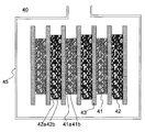
- FIG. 1 schematically shows an example of the configuration of a capacitor.
- the electrode plate group is configured by laminating a plurality of positive electrodes 41 and negative electrodes 42 via separators 43.
- the positive electrode 41 includes a positive electrode current collector 41a having a three-dimensional network structure, and a particulate positive electrode active material 41b filled in a communication hole of the positive electrode current collector 41a.
- the negative electrode 42 includes a negative electrode current collector 42a having a three-dimensional network structure, and a particulate negative electrode active material 42b filled in a communication hole of the negative electrode current collector 42a.
- the electrode plate group is not limited to the laminated type, and can also be configured by winding the positive electrode 41 and the negative electrode 42 via the separator 43. From the viewpoint of preventing lithium from being deposited on the negative electrode 42, it is desirable to make the size of the negative electrode 42 larger than that of the positive electrode 41 as shown in FIG. 1.
- Example 1 A lithium ion capacitor was produced according to the following procedure. (1) Preparation of positive electrode Activated carbon powder (specific surface area 2300 m 2 / g, average particle diameter of about 5 ⁇ m), acetylene black as a conductive auxiliary, PVDF as a binder (NMP solution containing PVDF at a concentration of 12% by mass), and a dispersion medium A positive electrode mixture slurry was prepared by mixing and stirring NMP in a mixer. The content of each component in the slurry was 21.5% by mass of activated carbon, 0.76% by mass of acetylene black, and 20.6% by mass of PVDF.
- the obtained positive electrode mixture slurry is applied to one surface (roughened surface) of an aluminum foil (thickness: 20 ⁇ m) as a current collector using a doctor blade to form a coating film having a thickness of 100 ⁇ m. Formed and dried at 100 ° C. for 30 minutes. The dried product was rolled using a pair of rolls to produce a positive electrode having a thickness of 65 ⁇ m.
- the obtained negative electrode mixture slurry is applied to one surface of a punching copper foil (thickness: 20 ⁇ m, opening diameter: 50 ⁇ m, opening ratio 50%) as a current collector using a doctor blade to have a thickness of 200 ⁇ m.
- a coating film was formed and dried at 100 ° C. for 30 minutes. The dried product was rolled using a pair of rolls to produce a negative electrode having a thickness of 120 ⁇ m.
- a lithium foil (thickness: 50 ⁇ m) is pressure-bonded to one surface of a punching copper foil (thickness: 20 ⁇ m, opening diameter: 50 ⁇ m, opening ratio 50%, 2 cm ⁇ 2 cm) as a current collector.
- a lithium electrode was produced.
- a nickel lead was welded to the other surface of the current collector.
- a single-cell electrode plate group was formed by laminating a positive electrode and a negative electrode with a cellulose separator (thickness: 60 ⁇ m) interposed between the positive electrode and the negative electrode. Furthermore, a lithium electrode is disposed on the negative electrode side of the electrode plate group with a polyolefin separator (a laminate of a polyethylene microporous membrane and a polypropylene microporous membrane) interposed therebetween. It accommodated in the cell case produced by.
- the electrolytic solution was injected into the cell case and impregnated into the positive electrode, the negative electrode, and the separator.
- an EMIFSI solution containing LiFSI as a lithium salt at a concentration of 1.0 mol / L was used.
- the cell case was sealed while reducing the pressure with a vacuum sealer.
- the negative electrode and the lithium electrode were connected to each other with a lead wire outside the cell case, and charged to 0 V with a current of 0.2 mA / cm 2 , so that the negative electrode active material was predoped with lithium. Thereafter, a discharge of 0.33 mAh was performed at a current of 0.2 mA / cm 2 . The voltage (initial voltage) at this time was measured. In this way, a lithium ion capacitor was produced. The amount of water in the electrolytic solution stored in the lithium ion capacitor was measured by the Karl Fischer method and found to be 108 ppm.
- Electrode capacity and C p / C n ratio Two positive electrodes were prepared, and a separator made of cellulose (thickness: 60 ⁇ m) was interposed between them to constitute an electrode plate group. Thereafter, the electrode plate group and the same electrolytic solution as described above were accommodated in an aluminum laminate bag to complete the EDLC. The obtained EDLC was charged and discharged with a voltage range of 0 to 4 V, and the reversible capacity C p of the positive electrode was determined from the discharge capacity at this time.
- a negative electrode and the same lithium electrode as described above were prepared, and a separator made of cellulose (thickness: 60 ⁇ m) was interposed between them to constitute an electrode plate group.
- a half cell was fabricated using the obtained electrode plate group and the same electrolytic solution as described above. The half cell was charged and discharged with a voltage range of 0 to 2.5 V, and the reversible capacity C n of the negative electrode was determined from the discharge capacity at this time. The C p / C n ratio was calculated by dividing the obtained C p by C n .
- Examples 2 to 4 and Comparative Examples 1 to 3 A lithium ion capacitor was produced and evaluated in the same manner as in Example 1 except that an electrolyte containing a lithium salt and a medium (ionic liquid or organic solvent) shown in Table 1 was used.
- a mixed solvent containing EC and DEC at a volume ratio of 1: 1 was used as the medium. The results are shown in Table 1.
- Comparative Examples 2 and 3 although the ionic liquid is used, the types of anions of the lithium salt and the ionic liquid are different. In these comparative examples, even if the upper limit voltage of charging was increased to 5.0 V, the swelling of the lithium ion capacitor as in comparative example 1 was not observed. However, in these comparative examples, decrease in discharge capacity of the lithium ion capacitor is significantly, the discharge capacity was less than 1/10 of C p. Moreover, when the charge capacity was evaluated for Comparative Examples 2 and 3, both values were about 0.15 mAh, which was half of C p . That is, in Comparative Examples 2 and 3, although the charge could be performed to some extent, the discharge amount relative to the charge amount was extremely small. Therefore, charging and discharging could not be performed stably and reversibly at a high charging voltage.
- Examples 5-8 Except for changing the concentration of the lithium salt in the electrolytic solution as shown in Table 2, a lithium ion capacitor was prepared and the upper limit voltage and discharge capacity were evaluated in the same manner as in Example 1. The results are shown in Table 2.
- Example 6 As in Example 1, charging and discharging could be performed stably even when the upper limit voltage for charging was 5 V, and a capacity comparable to or higher than C p could be secured. .
- Examples 5 and 8 although the discharge capacity of the lithium ion capacitor was slightly lower than C p , charging and discharging could be performed stably even when the upper limit voltage of charging was 5V.
- Example 5 when the charge capacity of the lithium ion capacitor was evaluated, the value exceeded 0.3 mAh and was comparable to C p .
- the lithium salt concentration is preferably more than 0.8 mol / L and less than 5.5 mol / L.
- Examples 9-14 A negative electrode and a lithium ion capacitor were prepared in the same manner as in Example 1 except that the thickness of the coating film of the negative electrode mixture slurry and the thickness of the negative electrode were changed as shown in Table 3. And the discharge capacity was evaluated. When the thickness of the coating film was less than 50 ⁇ m, the negative electrode mixture slurry was applied to the current collector using a spatula instead of the doctor blade. The results are shown in Table 3. In Table 3, the initial voltage of each lithium ion capacitor is also shown.
- Example 9 As in Example 1, even when the upper limit voltage for charging was 5 V, charging and discharging could be performed stably, and a high discharge capacity comparable to C p was obtained. In these examples, the initial voltage was also high. In Example 14, the initial voltage and discharge capacity of the lithium ion capacitor were lower than those in the other examples, but charging and discharging could be performed stably even when the upper limit voltage for charging was 5V. Note that if the initial voltage is small, the capacity tends to be small because it is necessary to leave the charged portion to fill the difference from the required voltage. Therefore, from the viewpoint of increasing the initial voltage and the discharge capacity, the C n / C p ratio is preferably larger than 1.1.
- Example 9 has a large C n / C p ratio, but the initial voltage is comparable. This is because if the amount of lithium doped into the negative electrode approaches the saturation amount, the potential of the negative electrode becomes approximately 0 V with respect to Li metal. Therefore, even if the C n / C p ratio is excessively increased, the discharge capacity of the lithium ion capacitor hardly changes. However, since the volume in the cell of the lithium ion capacitor increases as the amount of the negative electrode increases, the capacity density of the lithium ion capacitor decreases. Therefore, from the viewpoint of suppressing a decrease in the capacity density of the lithium ion capacitor while ensuring a sufficient discharge capacity, the C n / C p ratio is preferably less than 12.5.
- the lithium ion capacitor of the present invention can stably charge and discharge reversibly even if the charging voltage is increased, a high capacity lithium ion capacitor can be obtained. Therefore, the present invention can be applied to various power storage devices that require high capacity.
Landscapes
- Engineering & Computer Science (AREA)
- Power Engineering (AREA)
- Chemical & Material Sciences (AREA)
- Microelectronics & Electronic Packaging (AREA)
- Chemical Kinetics & Catalysis (AREA)
- Electrochemistry (AREA)
- Materials Engineering (AREA)
- Electric Double-Layer Capacitors Or The Like (AREA)
- Secondary Cells (AREA)
Abstract
Priority Applications (4)
| Application Number | Priority Date | Filing Date | Title |
|---|---|---|---|
| CN201480013669.2A CN105190810A (zh) | 2013-03-19 | 2014-03-05 | 锂离子电容器及其充放电方法 |
| EP14767837.9A EP2978002A4 (fr) | 2013-03-19 | 2014-03-05 | Condensateur lithium-ion et son procédé de chargement et déchargement |
| KR1020157024508A KR20150131019A (ko) | 2013-03-19 | 2014-03-05 | 리튬 이온 커패시터 및 그 충방전 방법 |
| US14/777,663 US20160111228A1 (en) | 2013-03-19 | 2014-03-05 | Lithium ion capacitor and method for charging and discharging same |
Applications Claiming Priority (2)
| Application Number | Priority Date | Filing Date | Title |
|---|---|---|---|
| JP2013-056297 | 2013-03-19 | ||
| JP2013056297A JP2014183161A (ja) | 2013-03-19 | 2013-03-19 | リチウムイオンキャパシタおよびその充放電方法 |
Publications (1)
| Publication Number | Publication Date |
|---|---|
| WO2014148250A1 true WO2014148250A1 (fr) | 2014-09-25 |
Family
ID=51579939
Family Applications (1)
| Application Number | Title | Priority Date | Filing Date |
|---|---|---|---|
| PCT/JP2014/055557 Ceased WO2014148250A1 (fr) | 2013-03-19 | 2014-03-05 | Condensateur lithium-ion et son procédé de chargement et déchargement |
Country Status (6)
| Country | Link |
|---|---|
| US (1) | US20160111228A1 (fr) |
| EP (1) | EP2978002A4 (fr) |
| JP (1) | JP2014183161A (fr) |
| KR (1) | KR20150131019A (fr) |
| CN (1) | CN105190810A (fr) |
| WO (1) | WO2014148250A1 (fr) |
Cited By (6)
| Publication number | Priority date | Publication date | Assignee | Title |
|---|---|---|---|---|
| WO2016159359A1 (fr) * | 2015-04-03 | 2016-10-06 | 日本ケミコン株式会社 | Condensateur hybride et séparateur pour condensateurs hybrides |
| CN106504912A (zh) * | 2015-09-04 | 2017-03-15 | 罗伯特·博世有限公司 | 混合超级电容器 |
| CN107112146A (zh) * | 2014-12-22 | 2017-08-29 | 日清纺控股株式会社 | 蓄电器件 |
| WO2017221830A1 (fr) * | 2016-06-22 | 2017-12-28 | 日本ケミコン株式会社 | Condensateur hybride et procédé de fabrication de celui-ci |
| EP3240094A4 (fr) * | 2014-12-22 | 2018-07-04 | Nisshinbo Holdings Inc. | Solution électrolytique pour batteries secondaires et batteries secondaires associées |
| CN119008835A (zh) * | 2024-09-27 | 2024-11-22 | 江苏新锂元科技有限公司 | 一种极片预锂化设备及极片预锂化方法 |
Families Citing this family (8)
| Publication number | Priority date | Publication date | Assignee | Title |
|---|---|---|---|---|
| US20160268064A1 (en) * | 2015-03-09 | 2016-09-15 | Semiconductor Energy Laboratory Co., Ltd. | Power storage device and electronic device |
| JP6361599B2 (ja) * | 2015-07-07 | 2018-07-25 | 株式会社豊田中央研究所 | 蓄電デバイス |
| KR101997746B1 (ko) * | 2015-09-24 | 2019-07-08 | 삼성전자주식회사 | 전지 팩 및 이의 충/방전 제어 방법 |
| JP6834187B2 (ja) * | 2016-06-22 | 2021-02-24 | 日本ケミコン株式会社 | ハイブリッドキャパシタ及びその製造方法 |
| CN106298263B (zh) * | 2016-10-31 | 2018-05-15 | 湘潭大学 | 一种铋/炭超级电容电池及其制备方法 |
| DE102020114893A1 (de) | 2020-06-04 | 2021-12-09 | Tdk Electronics Ag | Elektrochemische Zelle und elektrochemisches System |
| CN114597069B (zh) * | 2020-12-04 | 2024-02-02 | 位速科技股份有限公司 | 水相电解质溶液、蓄电装置及蓄电装置的制造方法 |
| TWI848434B (zh) * | 2022-11-11 | 2024-07-11 | 台灣中油股份有限公司 | 軟碳材料之負極的預鋰化方法及其超級電容 |
Citations (7)
| Publication number | Priority date | Publication date | Assignee | Title |
|---|---|---|---|---|
| JP2006155928A (ja) * | 2004-11-25 | 2006-06-15 | Gs Yuasa Corporation:Kk | 非水電解質および電気化学デバイス |
| JP2006260952A (ja) * | 2005-03-17 | 2006-09-28 | Toshiba Corp | 電気化学デバイス |
| JP2007294539A (ja) | 2006-04-21 | 2007-11-08 | Advanced Capacitor Technologies Inc | リチウムイオンハイブリッドキャパシタ |
| JP2010097922A (ja) | 2008-09-17 | 2010-04-30 | Dai Ichi Kogyo Seiyaku Co Ltd | イオン液体を用いたリチウム二次電池 |
| JP2010140941A (ja) * | 2008-12-09 | 2010-06-24 | Sumitomo Electric Ind Ltd | キャパシタ |
| JP2012142340A (ja) | 2010-12-28 | 2012-07-26 | Jm Energy Corp | リチウムイオンキャパシタ |
| JP2013026444A (ja) * | 2011-07-21 | 2013-02-04 | Sumitomo Electric Ind Ltd | 非水電解質電気化学素子用電極の製造方法およびその非水電解質電気化学素子用電極を備えた非水電解質電気化学素子 |
Family Cites Families (15)
| Publication number | Priority date | Publication date | Assignee | Title |
|---|---|---|---|---|
| DE602005017837D1 (de) * | 2004-01-15 | 2010-01-07 | Panasonic Corp | Nichtwässriger Elektrolyt für elektrochemische Vorrichtungen |
| US7582380B1 (en) * | 2004-04-08 | 2009-09-01 | Electrochemical Systems, Inc. | Lithium-ion cell with a wide operating temperature range |
| JP2006286921A (ja) * | 2005-03-31 | 2006-10-19 | Fuji Heavy Ind Ltd | リチウムイオンキャパシタ |
| JP4731967B2 (ja) * | 2005-03-31 | 2011-07-27 | 富士重工業株式会社 | リチウムイオンキャパシタ |
| JP2008294314A (ja) * | 2007-05-28 | 2008-12-04 | Sanyo Electric Co Ltd | キャパシタ |
| EP2023434B1 (fr) * | 2007-07-23 | 2016-09-07 | Litarion GmbH | Préparations d'électrolytes pour accumulateurs d'énergie à base de liquides ioniques |
| JP5242973B2 (ja) * | 2007-08-23 | 2013-07-24 | 日本化学工業株式会社 | 蓄電デバイス用電解質組成物及びそれを用いた蓄電デバイス |
| JP5163216B2 (ja) * | 2008-03-25 | 2013-03-13 | 日本ゼオン株式会社 | ハイブリッドキャパシタ用電極およびハイブリッドキャパシタ |
| US8822078B2 (en) * | 2008-09-29 | 2014-09-02 | Rochester Institute Of Technology | Freestanding carbon nanotube paper, methods of its making, and devices containing the same |
| JP5408702B2 (ja) * | 2009-01-23 | 2014-02-05 | Necエナジーデバイス株式会社 | リチウムイオン電池 |
| JP5446309B2 (ja) * | 2009-02-20 | 2014-03-19 | ソニー株式会社 | ゲル状電解質及びこれを用いた電池とその使用方法、並びにゲル状電解質の製造方法 |
| CN101841064A (zh) * | 2010-05-20 | 2010-09-22 | 中南大学 | 具有高容量与库仑效率的锂离子电容电池负极系统 |
| CN103201805B (zh) * | 2010-11-10 | 2016-01-27 | Jm能源股份有限公司 | 锂离子电容器 |
| JP2012212632A (ja) * | 2011-03-31 | 2012-11-01 | Fuji Heavy Ind Ltd | リチウムイオン蓄電デバイスの製造方法 |
| JP2012216401A (ja) * | 2011-03-31 | 2012-11-08 | Fuji Heavy Ind Ltd | リチウムイオン蓄電デバイス |
-
2013
- 2013-03-19 JP JP2013056297A patent/JP2014183161A/ja active Pending
-
2014
- 2014-03-05 WO PCT/JP2014/055557 patent/WO2014148250A1/fr not_active Ceased
- 2014-03-05 CN CN201480013669.2A patent/CN105190810A/zh active Pending
- 2014-03-05 US US14/777,663 patent/US20160111228A1/en not_active Abandoned
- 2014-03-05 KR KR1020157024508A patent/KR20150131019A/ko not_active Withdrawn
- 2014-03-05 EP EP14767837.9A patent/EP2978002A4/fr not_active Withdrawn
Patent Citations (7)
| Publication number | Priority date | Publication date | Assignee | Title |
|---|---|---|---|---|
| JP2006155928A (ja) * | 2004-11-25 | 2006-06-15 | Gs Yuasa Corporation:Kk | 非水電解質および電気化学デバイス |
| JP2006260952A (ja) * | 2005-03-17 | 2006-09-28 | Toshiba Corp | 電気化学デバイス |
| JP2007294539A (ja) | 2006-04-21 | 2007-11-08 | Advanced Capacitor Technologies Inc | リチウムイオンハイブリッドキャパシタ |
| JP2010097922A (ja) | 2008-09-17 | 2010-04-30 | Dai Ichi Kogyo Seiyaku Co Ltd | イオン液体を用いたリチウム二次電池 |
| JP2010140941A (ja) * | 2008-12-09 | 2010-06-24 | Sumitomo Electric Ind Ltd | キャパシタ |
| JP2012142340A (ja) | 2010-12-28 | 2012-07-26 | Jm Energy Corp | リチウムイオンキャパシタ |
| JP2013026444A (ja) * | 2011-07-21 | 2013-02-04 | Sumitomo Electric Ind Ltd | 非水電解質電気化学素子用電極の製造方法およびその非水電解質電気化学素子用電極を備えた非水電解質電気化学素子 |
Non-Patent Citations (1)
| Title |
|---|
| See also references of EP2978002A4 |
Cited By (13)
| Publication number | Priority date | Publication date | Assignee | Title |
|---|---|---|---|---|
| EP3240000A4 (fr) * | 2014-12-22 | 2018-07-04 | Nisshinbo Holdings Inc. | Dispositif d'accumulation d'électricté |
| US10763548B2 (en) | 2014-12-22 | 2020-09-01 | Nisshinbo Holdings, Inc. | Electrolyte solution for secondary batteries, and secondary battery |
| CN107112146A (zh) * | 2014-12-22 | 2017-08-29 | 日清纺控股株式会社 | 蓄电器件 |
| EP3240094A4 (fr) * | 2014-12-22 | 2018-07-04 | Nisshinbo Holdings Inc. | Solution électrolytique pour batteries secondaires et batteries secondaires associées |
| US10504661B2 (en) | 2015-04-03 | 2019-12-10 | Nippon Chemi-Con Corporation | Hybrid capacitor and separator for hybrid capacitors |
| JPWO2016159359A1 (ja) * | 2015-04-03 | 2018-02-08 | 日本ケミコン株式会社 | ハイブリッドキャパシタ及びハイブリッドキャパシタ用セパレータ |
| EP3279911A4 (fr) * | 2015-04-03 | 2018-11-14 | Nippon Chemi-Con Corporation | Condensateur hybride et séparateur pour condensateurs hybrides |
| WO2016159359A1 (fr) * | 2015-04-03 | 2016-10-06 | 日本ケミコン株式会社 | Condensateur hybride et séparateur pour condensateurs hybrides |
| CN106504912A (zh) * | 2015-09-04 | 2017-03-15 | 罗伯特·博世有限公司 | 混合超级电容器 |
| JP2017228664A (ja) * | 2016-06-22 | 2017-12-28 | 日本ケミコン株式会社 | ハイブリッドキャパシタ及びその製造方法 |
| WO2017221830A1 (fr) * | 2016-06-22 | 2017-12-28 | 日本ケミコン株式会社 | Condensateur hybride et procédé de fabrication de celui-ci |
| US11152159B2 (en) | 2016-06-22 | 2021-10-19 | Nippon Chemi-Con Corporation | Hybrid capacitor and manufacturing method thereof |
| CN119008835A (zh) * | 2024-09-27 | 2024-11-22 | 江苏新锂元科技有限公司 | 一种极片预锂化设备及极片预锂化方法 |
Also Published As
| Publication number | Publication date |
|---|---|
| KR20150131019A (ko) | 2015-11-24 |
| JP2014183161A (ja) | 2014-09-29 |
| CN105190810A (zh) | 2015-12-23 |
| EP2978002A1 (fr) | 2016-01-27 |
| EP2978002A4 (fr) | 2016-10-26 |
| US20160111228A1 (en) | 2016-04-21 |
Similar Documents
| Publication | Publication Date | Title |
|---|---|---|
| WO2014148250A1 (fr) | Condensateur lithium-ion et son procédé de chargement et déchargement | |
| US9786443B2 (en) | Capacitor and method for charging and discharging the same | |
| WO2014208182A1 (fr) | Batterie au lithium | |
| US20170194106A1 (en) | Electricity storage device and charge/discharge system | |
| KR20160102974A (ko) | 알칼리 금속 이온 커패시터 | |
| WO2015076059A1 (fr) | Condensateur et son procédé de fabrication | |
| JP6260209B2 (ja) | アルカリ金属イオンキャパシタ、その製造方法および充放電方法 | |
| JP2015153700A (ja) | 蓄電デバイス | |
| US20170011860A1 (en) | Capacitor and method for charging and discharging same | |
| JP2015041433A (ja) | ナトリウム溶融塩電池 | |
| WO2014050541A1 (fr) | Condensateur à sel fondu | |
| JP2015135947A (ja) | リチウムイオンキャパシタ | |
| JP2017041462A (ja) | アルミニウム多孔体、蓄電デバイス用電極および蓄電デバイス | |
| JP2015137365A (ja) | 銅多孔体、蓄電デバイス用電極および蓄電デバイス | |
| WO2016056494A1 (fr) | Électrolyte pour batterie secondaire au sodium-ion, et batterie rechargeable au sodium-ion | |
| JP2015204437A (ja) | リチウムイオンキャパシタ | |
| JP2015153699A (ja) | 蓄電デバイス | |
| JP2015115336A (ja) | キャパシタおよびその充放電方法 | |
| JP2016181603A (ja) | リチウムイオンキャパシタ |
Legal Events
| Date | Code | Title | Description |
|---|---|---|---|
| WWE | Wipo information: entry into national phase |
Ref document number: 201480013669.2 Country of ref document: CN |
|
| 121 | Ep: the epo has been informed by wipo that ep was designated in this application |
Ref document number: 14767837 Country of ref document: EP Kind code of ref document: A1 |
|
| ENP | Entry into the national phase |
Ref document number: 20157024508 Country of ref document: KR Kind code of ref document: A |
|
| REEP | Request for entry into the european phase |
Ref document number: 2014767837 Country of ref document: EP |
|
| WWE | Wipo information: entry into national phase |
Ref document number: 2014767837 Country of ref document: EP |
|
| WWE | Wipo information: entry into national phase |
Ref document number: 14777663 Country of ref document: US |
|
| NENP | Non-entry into the national phase |
Ref country code: DE |