WO2014148376A1 - ハイブリッド車両 - Google Patents
ハイブリッド車両 Download PDFInfo
- Publication number
- WO2014148376A1 WO2014148376A1 PCT/JP2014/056871 JP2014056871W WO2014148376A1 WO 2014148376 A1 WO2014148376 A1 WO 2014148376A1 JP 2014056871 W JP2014056871 W JP 2014056871W WO 2014148376 A1 WO2014148376 A1 WO 2014148376A1
- Authority
- WO
- WIPO (PCT)
- Prior art keywords
- oil pump
- mode
- engine
- gear ratio
- speed
- Prior art date
- Legal status (The legal status is an assumption and is not a legal conclusion. Google has not performed a legal analysis and makes no representation as to the accuracy of the status listed.)
- Ceased
Links
Images










Classifications
-
- B—PERFORMING OPERATIONS; TRANSPORTING
- B60—VEHICLES IN GENERAL
- B60W—CONJOINT CONTROL OF VEHICLE SUB-UNITS OF DIFFERENT TYPE OR DIFFERENT FUNCTION; CONTROL SYSTEMS SPECIALLY ADAPTED FOR HYBRID VEHICLES; ROAD VEHICLE DRIVE CONTROL SYSTEMS FOR PURPOSES NOT RELATED TO THE CONTROL OF A PARTICULAR SUB-UNIT
- B60W20/00—Control systems specially adapted for hybrid vehicles
- B60W20/40—Controlling the engagement or disengagement of prime movers, e.g. for transition between prime movers
-
- B—PERFORMING OPERATIONS; TRANSPORTING
- B60—VEHICLES IN GENERAL
- B60K—ARRANGEMENT OR MOUNTING OF PROPULSION UNITS OR OF TRANSMISSIONS IN VEHICLES; ARRANGEMENT OR MOUNTING OF PLURAL DIVERSE PRIME-MOVERS IN VEHICLES; AUXILIARY DRIVES FOR VEHICLES; INSTRUMENTATION OR DASHBOARDS FOR VEHICLES; ARRANGEMENTS IN CONNECTION WITH COOLING, AIR INTAKE, GAS EXHAUST OR FUEL SUPPLY OF PROPULSION UNITS IN VEHICLES
- B60K6/00—Arrangement or mounting of plural diverse prime-movers for mutual or common propulsion, e.g. hybrid propulsion systems comprising electric motors and internal combustion engines
- B60K6/20—Arrangement or mounting of plural diverse prime-movers for mutual or common propulsion, e.g. hybrid propulsion systems comprising electric motors and internal combustion engines the prime-movers consisting of electric motors and internal combustion engines, e.g. HEVs
- B60K6/42—Arrangement or mounting of plural diverse prime-movers for mutual or common propulsion, e.g. hybrid propulsion systems comprising electric motors and internal combustion engines the prime-movers consisting of electric motors and internal combustion engines, e.g. HEVs characterised by the architecture of the hybrid electric vehicle
- B60K6/48—Parallel type
-
- B—PERFORMING OPERATIONS; TRANSPORTING
- B60—VEHICLES IN GENERAL
- B60K—ARRANGEMENT OR MOUNTING OF PROPULSION UNITS OR OF TRANSMISSIONS IN VEHICLES; ARRANGEMENT OR MOUNTING OF PLURAL DIVERSE PRIME-MOVERS IN VEHICLES; AUXILIARY DRIVES FOR VEHICLES; INSTRUMENTATION OR DASHBOARDS FOR VEHICLES; ARRANGEMENTS IN CONNECTION WITH COOLING, AIR INTAKE, GAS EXHAUST OR FUEL SUPPLY OF PROPULSION UNITS IN VEHICLES
- B60K6/00—Arrangement or mounting of plural diverse prime-movers for mutual or common propulsion, e.g. hybrid propulsion systems comprising electric motors and internal combustion engines
- B60K6/20—Arrangement or mounting of plural diverse prime-movers for mutual or common propulsion, e.g. hybrid propulsion systems comprising electric motors and internal combustion engines the prime-movers consisting of electric motors and internal combustion engines, e.g. HEVs
- B60K6/50—Architecture of the driveline characterised by arrangement or kind of transmission units
- B60K6/54—Transmission for changing ratio
- B60K6/543—Transmission for changing ratio the transmission being a continuously variable transmission
-
- B—PERFORMING OPERATIONS; TRANSPORTING
- B60—VEHICLES IN GENERAL
- B60L—PROPULSION OF ELECTRICALLY-PROPELLED VEHICLES; SUPPLYING ELECTRIC POWER FOR AUXILIARY EQUIPMENT OF ELECTRICALLY-PROPELLED VEHICLES; ELECTRODYNAMIC BRAKE SYSTEMS FOR VEHICLES IN GENERAL; MAGNETIC SUSPENSION OR LEVITATION FOR VEHICLES; MONITORING OPERATING VARIABLES OF ELECTRICALLY-PROPELLED VEHICLES; ELECTRIC SAFETY DEVICES FOR ELECTRICALLY-PROPELLED VEHICLES
- B60L1/00—Supplying electric power to auxiliary equipment of vehicles
- B60L1/003—Supplying electric power to auxiliary equipment of vehicles to auxiliary motors, e.g. for pumps, compressors
-
- B—PERFORMING OPERATIONS; TRANSPORTING
- B60—VEHICLES IN GENERAL
- B60L—PROPULSION OF ELECTRICALLY-PROPELLED VEHICLES; SUPPLYING ELECTRIC POWER FOR AUXILIARY EQUIPMENT OF ELECTRICALLY-PROPELLED VEHICLES; ELECTRODYNAMIC BRAKE SYSTEMS FOR VEHICLES IN GENERAL; MAGNETIC SUSPENSION OR LEVITATION FOR VEHICLES; MONITORING OPERATING VARIABLES OF ELECTRICALLY-PROPELLED VEHICLES; ELECTRIC SAFETY DEVICES FOR ELECTRICALLY-PROPELLED VEHICLES
- B60L15/00—Methods, circuits, or devices for controlling the traction-motor speed of electrically-propelled vehicles
- B60L15/20—Methods, circuits, or devices for controlling the traction-motor speed of electrically-propelled vehicles for control of the vehicle or its driving motor to achieve a desired performance, e.g. speed, torque, programmed variation of speed
- B60L15/2009—Methods, circuits, or devices for controlling the traction-motor speed of electrically-propelled vehicles for control of the vehicle or its driving motor to achieve a desired performance, e.g. speed, torque, programmed variation of speed for braking
-
- B—PERFORMING OPERATIONS; TRANSPORTING
- B60—VEHICLES IN GENERAL
- B60L—PROPULSION OF ELECTRICALLY-PROPELLED VEHICLES; SUPPLYING ELECTRIC POWER FOR AUXILIARY EQUIPMENT OF ELECTRICALLY-PROPELLED VEHICLES; ELECTRODYNAMIC BRAKE SYSTEMS FOR VEHICLES IN GENERAL; MAGNETIC SUSPENSION OR LEVITATION FOR VEHICLES; MONITORING OPERATING VARIABLES OF ELECTRICALLY-PROPELLED VEHICLES; ELECTRIC SAFETY DEVICES FOR ELECTRICALLY-PROPELLED VEHICLES
- B60L15/00—Methods, circuits, or devices for controlling the traction-motor speed of electrically-propelled vehicles
- B60L15/20—Methods, circuits, or devices for controlling the traction-motor speed of electrically-propelled vehicles for control of the vehicle or its driving motor to achieve a desired performance, e.g. speed, torque, programmed variation of speed
- B60L15/2054—Methods, circuits, or devices for controlling the traction-motor speed of electrically-propelled vehicles for control of the vehicle or its driving motor to achieve a desired performance, e.g. speed, torque, programmed variation of speed by controlling transmissions or clutches
-
- B—PERFORMING OPERATIONS; TRANSPORTING
- B60—VEHICLES IN GENERAL
- B60L—PROPULSION OF ELECTRICALLY-PROPELLED VEHICLES; SUPPLYING ELECTRIC POWER FOR AUXILIARY EQUIPMENT OF ELECTRICALLY-PROPELLED VEHICLES; ELECTRODYNAMIC BRAKE SYSTEMS FOR VEHICLES IN GENERAL; MAGNETIC SUSPENSION OR LEVITATION FOR VEHICLES; MONITORING OPERATING VARIABLES OF ELECTRICALLY-PROPELLED VEHICLES; ELECTRIC SAFETY DEVICES FOR ELECTRICALLY-PROPELLED VEHICLES
- B60L50/00—Electric propulsion with power supplied within the vehicle
- B60L50/10—Electric propulsion with power supplied within the vehicle using propulsion power supplied by engine-driven generators, e.g. generators driven by combustion engines
- B60L50/16—Electric propulsion with power supplied within the vehicle using propulsion power supplied by engine-driven generators, e.g. generators driven by combustion engines with provision for separate direct mechanical propulsion
-
- B—PERFORMING OPERATIONS; TRANSPORTING
- B60—VEHICLES IN GENERAL
- B60L—PROPULSION OF ELECTRICALLY-PROPELLED VEHICLES; SUPPLYING ELECTRIC POWER FOR AUXILIARY EQUIPMENT OF ELECTRICALLY-PROPELLED VEHICLES; ELECTRODYNAMIC BRAKE SYSTEMS FOR VEHICLES IN GENERAL; MAGNETIC SUSPENSION OR LEVITATION FOR VEHICLES; MONITORING OPERATING VARIABLES OF ELECTRICALLY-PROPELLED VEHICLES; ELECTRIC SAFETY DEVICES FOR ELECTRICALLY-PROPELLED VEHICLES
- B60L7/00—Electrodynamic brake systems for vehicles in general
- B60L7/10—Dynamic electric regenerative braking
- B60L7/14—Dynamic electric regenerative braking for vehicles propelled by AC motors
-
- B—PERFORMING OPERATIONS; TRANSPORTING
- B60—VEHICLES IN GENERAL
- B60W—CONJOINT CONTROL OF VEHICLE SUB-UNITS OF DIFFERENT TYPE OR DIFFERENT FUNCTION; CONTROL SYSTEMS SPECIALLY ADAPTED FOR HYBRID VEHICLES; ROAD VEHICLE DRIVE CONTROL SYSTEMS FOR PURPOSES NOT RELATED TO THE CONTROL OF A PARTICULAR SUB-UNIT
- B60W10/00—Conjoint control of vehicle sub-units of different type or different function
- B60W10/02—Conjoint control of vehicle sub-units of different type or different function including control of driveline clutches
-
- B—PERFORMING OPERATIONS; TRANSPORTING
- B60—VEHICLES IN GENERAL
- B60W—CONJOINT CONTROL OF VEHICLE SUB-UNITS OF DIFFERENT TYPE OR DIFFERENT FUNCTION; CONTROL SYSTEMS SPECIALLY ADAPTED FOR HYBRID VEHICLES; ROAD VEHICLE DRIVE CONTROL SYSTEMS FOR PURPOSES NOT RELATED TO THE CONTROL OF A PARTICULAR SUB-UNIT
- B60W10/00—Conjoint control of vehicle sub-units of different type or different function
- B60W10/04—Conjoint control of vehicle sub-units of different type or different function including control of propulsion units
- B60W10/06—Conjoint control of vehicle sub-units of different type or different function including control of propulsion units including control of combustion engines
-
- B—PERFORMING OPERATIONS; TRANSPORTING
- B60—VEHICLES IN GENERAL
- B60W—CONJOINT CONTROL OF VEHICLE SUB-UNITS OF DIFFERENT TYPE OR DIFFERENT FUNCTION; CONTROL SYSTEMS SPECIALLY ADAPTED FOR HYBRID VEHICLES; ROAD VEHICLE DRIVE CONTROL SYSTEMS FOR PURPOSES NOT RELATED TO THE CONTROL OF A PARTICULAR SUB-UNIT
- B60W10/00—Conjoint control of vehicle sub-units of different type or different function
- B60W10/10—Conjoint control of vehicle sub-units of different type or different function including control of change-speed gearings
- B60W10/101—Infinitely variable gearings
- B60W10/107—Infinitely variable gearings with endless flexible members
-
- F—MECHANICAL ENGINEERING; LIGHTING; HEATING; WEAPONS; BLASTING
- F16—ENGINEERING ELEMENTS AND UNITS; GENERAL MEASURES FOR PRODUCING AND MAINTAINING EFFECTIVE FUNCTIONING OF MACHINES OR INSTALLATIONS; THERMAL INSULATION IN GENERAL
- F16H—GEARING
- F16H61/00—Control functions within control units of change-speed- or reversing-gearings for conveying rotary motion ; Control of exclusively fluid gearing, friction gearing, gearings with endless flexible members or other particular types of gearing
- F16H61/0021—Generation or control of line pressure
- F16H61/0025—Supply of control fluid; Pumps therefor
- F16H61/0031—Supply of control fluid; Pumps therefor using auxiliary pumps, e.g. pump driven by a different power source than the engine
-
- F—MECHANICAL ENGINEERING; LIGHTING; HEATING; WEAPONS; BLASTING
- F16—ENGINEERING ELEMENTS AND UNITS; GENERAL MEASURES FOR PRODUCING AND MAINTAINING EFFECTIVE FUNCTIONING OF MACHINES OR INSTALLATIONS; THERMAL INSULATION IN GENERAL
- F16H—GEARING
- F16H61/00—Control functions within control units of change-speed- or reversing-gearings for conveying rotary motion ; Control of exclusively fluid gearing, friction gearing, gearings with endless flexible members or other particular types of gearing
- F16H61/66—Control functions within control units of change-speed- or reversing-gearings for conveying rotary motion ; Control of exclusively fluid gearing, friction gearing, gearings with endless flexible members or other particular types of gearing specially adapted for continuously variable gearings
- F16H61/662—Control functions within control units of change-speed- or reversing-gearings for conveying rotary motion ; Control of exclusively fluid gearing, friction gearing, gearings with endless flexible members or other particular types of gearing specially adapted for continuously variable gearings with endless flexible members
- F16H61/66272—Control functions within control units of change-speed- or reversing-gearings for conveying rotary motion ; Control of exclusively fluid gearing, friction gearing, gearings with endless flexible members or other particular types of gearing specially adapted for continuously variable gearings with endless flexible members characterised by means for controlling the torque transmitting capability of the gearing
-
- B—PERFORMING OPERATIONS; TRANSPORTING
- B60—VEHICLES IN GENERAL
- B60K—ARRANGEMENT OR MOUNTING OF PROPULSION UNITS OR OF TRANSMISSIONS IN VEHICLES; ARRANGEMENT OR MOUNTING OF PLURAL DIVERSE PRIME-MOVERS IN VEHICLES; AUXILIARY DRIVES FOR VEHICLES; INSTRUMENTATION OR DASHBOARDS FOR VEHICLES; ARRANGEMENTS IN CONNECTION WITH COOLING, AIR INTAKE, GAS EXHAUST OR FUEL SUPPLY OF PROPULSION UNITS IN VEHICLES
- B60K6/00—Arrangement or mounting of plural diverse prime-movers for mutual or common propulsion, e.g. hybrid propulsion systems comprising electric motors and internal combustion engines
- B60K6/20—Arrangement or mounting of plural diverse prime-movers for mutual or common propulsion, e.g. hybrid propulsion systems comprising electric motors and internal combustion engines the prime-movers consisting of electric motors and internal combustion engines, e.g. HEVs
- B60K6/42—Arrangement or mounting of plural diverse prime-movers for mutual or common propulsion, e.g. hybrid propulsion systems comprising electric motors and internal combustion engines the prime-movers consisting of electric motors and internal combustion engines, e.g. HEVs characterised by the architecture of the hybrid electric vehicle
- B60K6/48—Parallel type
- B60K2006/4808—Electric machine connected or connectable to gearbox output shaft
-
- B—PERFORMING OPERATIONS; TRANSPORTING
- B60—VEHICLES IN GENERAL
- B60L—PROPULSION OF ELECTRICALLY-PROPELLED VEHICLES; SUPPLYING ELECTRIC POWER FOR AUXILIARY EQUIPMENT OF ELECTRICALLY-PROPELLED VEHICLES; ELECTRODYNAMIC BRAKE SYSTEMS FOR VEHICLES IN GENERAL; MAGNETIC SUSPENSION OR LEVITATION FOR VEHICLES; MONITORING OPERATING VARIABLES OF ELECTRICALLY-PROPELLED VEHICLES; ELECTRIC SAFETY DEVICES FOR ELECTRICALLY-PROPELLED VEHICLES
- B60L2240/00—Control parameters of input or output; Target parameters
- B60L2240/10—Vehicle control parameters
- B60L2240/12—Speed
-
- B—PERFORMING OPERATIONS; TRANSPORTING
- B60—VEHICLES IN GENERAL
- B60L—PROPULSION OF ELECTRICALLY-PROPELLED VEHICLES; SUPPLYING ELECTRIC POWER FOR AUXILIARY EQUIPMENT OF ELECTRICALLY-PROPELLED VEHICLES; ELECTRODYNAMIC BRAKE SYSTEMS FOR VEHICLES IN GENERAL; MAGNETIC SUSPENSION OR LEVITATION FOR VEHICLES; MONITORING OPERATING VARIABLES OF ELECTRICALLY-PROPELLED VEHICLES; ELECTRIC SAFETY DEVICES FOR ELECTRICALLY-PROPELLED VEHICLES
- B60L2240/00—Control parameters of input or output; Target parameters
- B60L2240/40—Drive Train control parameters
- B60L2240/50—Drive Train control parameters related to clutches
- B60L2240/507—Operating parameters
-
- B—PERFORMING OPERATIONS; TRANSPORTING
- B60—VEHICLES IN GENERAL
- B60L—PROPULSION OF ELECTRICALLY-PROPELLED VEHICLES; SUPPLYING ELECTRIC POWER FOR AUXILIARY EQUIPMENT OF ELECTRICALLY-PROPELLED VEHICLES; ELECTRODYNAMIC BRAKE SYSTEMS FOR VEHICLES IN GENERAL; MAGNETIC SUSPENSION OR LEVITATION FOR VEHICLES; MONITORING OPERATING VARIABLES OF ELECTRICALLY-PROPELLED VEHICLES; ELECTRIC SAFETY DEVICES FOR ELECTRICALLY-PROPELLED VEHICLES
- B60L2250/00—Driver interactions
- B60L2250/26—Driver interactions by pedal actuation
-
- B—PERFORMING OPERATIONS; TRANSPORTING
- B60—VEHICLES IN GENERAL
- B60L—PROPULSION OF ELECTRICALLY-PROPELLED VEHICLES; SUPPLYING ELECTRIC POWER FOR AUXILIARY EQUIPMENT OF ELECTRICALLY-PROPELLED VEHICLES; ELECTRODYNAMIC BRAKE SYSTEMS FOR VEHICLES IN GENERAL; MAGNETIC SUSPENSION OR LEVITATION FOR VEHICLES; MONITORING OPERATING VARIABLES OF ELECTRICALLY-PROPELLED VEHICLES; ELECTRIC SAFETY DEVICES FOR ELECTRICALLY-PROPELLED VEHICLES
- B60L2270/00—Problem solutions or means not otherwise provided for
- B60L2270/10—Emission reduction
- B60L2270/14—Emission reduction of noise
- B60L2270/145—Structure borne vibrations
-
- B—PERFORMING OPERATIONS; TRANSPORTING
- B60—VEHICLES IN GENERAL
- B60W—CONJOINT CONTROL OF VEHICLE SUB-UNITS OF DIFFERENT TYPE OR DIFFERENT FUNCTION; CONTROL SYSTEMS SPECIALLY ADAPTED FOR HYBRID VEHICLES; ROAD VEHICLE DRIVE CONTROL SYSTEMS FOR PURPOSES NOT RELATED TO THE CONTROL OF A PARTICULAR SUB-UNIT
- B60W2710/00—Output or target parameters relating to a particular sub-units
- B60W2710/10—Change speed gearings
- B60W2710/1005—Transmission ratio engaged
-
- B—PERFORMING OPERATIONS; TRANSPORTING
- B60—VEHICLES IN GENERAL
- B60W—CONJOINT CONTROL OF VEHICLE SUB-UNITS OF DIFFERENT TYPE OR DIFFERENT FUNCTION; CONTROL SYSTEMS SPECIALLY ADAPTED FOR HYBRID VEHICLES; ROAD VEHICLE DRIVE CONTROL SYSTEMS FOR PURPOSES NOT RELATED TO THE CONTROL OF A PARTICULAR SUB-UNIT
- B60W2710/00—Output or target parameters relating to a particular sub-units
- B60W2710/10—Change speed gearings
- B60W2710/1077—Change speed gearings fluid pressure, e.g. oil pressure
- B60W2710/1083—Change speed gearings fluid pressure, e.g. oil pressure pressure of control fluid
-
- F—MECHANICAL ENGINEERING; LIGHTING; HEATING; WEAPONS; BLASTING
- F16—ENGINEERING ELEMENTS AND UNITS; GENERAL MEASURES FOR PRODUCING AND MAINTAINING EFFECTIVE FUNCTIONING OF MACHINES OR INSTALLATIONS; THERMAL INSULATION IN GENERAL
- F16H—GEARING
- F16H61/00—Control functions within control units of change-speed- or reversing-gearings for conveying rotary motion ; Control of exclusively fluid gearing, friction gearing, gearings with endless flexible members or other particular types of gearing
- F16H61/66—Control functions within control units of change-speed- or reversing-gearings for conveying rotary motion ; Control of exclusively fluid gearing, friction gearing, gearings with endless flexible members or other particular types of gearing specially adapted for continuously variable gearings
- F16H61/662—Control functions within control units of change-speed- or reversing-gearings for conveying rotary motion ; Control of exclusively fluid gearing, friction gearing, gearings with endless flexible members or other particular types of gearing specially adapted for continuously variable gearings with endless flexible members
- F16H2061/66286—Control for optimising pump efficiency
-
- Y—GENERAL TAGGING OF NEW TECHNOLOGICAL DEVELOPMENTS; GENERAL TAGGING OF CROSS-SECTIONAL TECHNOLOGIES SPANNING OVER SEVERAL SECTIONS OF THE IPC; TECHNICAL SUBJECTS COVERED BY FORMER USPC CROSS-REFERENCE ART COLLECTIONS [XRACs] AND DIGESTS
- Y02—TECHNOLOGIES OR APPLICATIONS FOR MITIGATION OR ADAPTATION AGAINST CLIMATE CHANGE
- Y02T—CLIMATE CHANGE MITIGATION TECHNOLOGIES RELATED TO TRANSPORTATION
- Y02T10/00—Road transport of goods or passengers
- Y02T10/60—Other road transportation technologies with climate change mitigation effect
- Y02T10/62—Hybrid vehicles
-
- Y—GENERAL TAGGING OF NEW TECHNOLOGICAL DEVELOPMENTS; GENERAL TAGGING OF CROSS-SECTIONAL TECHNOLOGIES SPANNING OVER SEVERAL SECTIONS OF THE IPC; TECHNICAL SUBJECTS COVERED BY FORMER USPC CROSS-REFERENCE ART COLLECTIONS [XRACs] AND DIGESTS
- Y02—TECHNOLOGIES OR APPLICATIONS FOR MITIGATION OR ADAPTATION AGAINST CLIMATE CHANGE
- Y02T—CLIMATE CHANGE MITIGATION TECHNOLOGIES RELATED TO TRANSPORTATION
- Y02T10/00—Road transport of goods or passengers
- Y02T10/60—Other road transportation technologies with climate change mitigation effect
- Y02T10/64—Electric machine technologies in electromobility
-
- Y—GENERAL TAGGING OF NEW TECHNOLOGICAL DEVELOPMENTS; GENERAL TAGGING OF CROSS-SECTIONAL TECHNOLOGIES SPANNING OVER SEVERAL SECTIONS OF THE IPC; TECHNICAL SUBJECTS COVERED BY FORMER USPC CROSS-REFERENCE ART COLLECTIONS [XRACs] AND DIGESTS
- Y02—TECHNOLOGIES OR APPLICATIONS FOR MITIGATION OR ADAPTATION AGAINST CLIMATE CHANGE
- Y02T—CLIMATE CHANGE MITIGATION TECHNOLOGIES RELATED TO TRANSPORTATION
- Y02T10/00—Road transport of goods or passengers
- Y02T10/60—Other road transportation technologies with climate change mitigation effect
- Y02T10/70—Energy storage systems for electromobility, e.g. batteries
-
- Y—GENERAL TAGGING OF NEW TECHNOLOGICAL DEVELOPMENTS; GENERAL TAGGING OF CROSS-SECTIONAL TECHNOLOGIES SPANNING OVER SEVERAL SECTIONS OF THE IPC; TECHNICAL SUBJECTS COVERED BY FORMER USPC CROSS-REFERENCE ART COLLECTIONS [XRACs] AND DIGESTS
- Y02—TECHNOLOGIES OR APPLICATIONS FOR MITIGATION OR ADAPTATION AGAINST CLIMATE CHANGE
- Y02T—CLIMATE CHANGE MITIGATION TECHNOLOGIES RELATED TO TRANSPORTATION
- Y02T10/00—Road transport of goods or passengers
- Y02T10/60—Other road transportation technologies with climate change mitigation effect
- Y02T10/7072—Electromobility specific charging systems or methods for batteries, ultracapacitors, supercapacitors or double-layer capacitors
-
- Y—GENERAL TAGGING OF NEW TECHNOLOGICAL DEVELOPMENTS; GENERAL TAGGING OF CROSS-SECTIONAL TECHNOLOGIES SPANNING OVER SEVERAL SECTIONS OF THE IPC; TECHNICAL SUBJECTS COVERED BY FORMER USPC CROSS-REFERENCE ART COLLECTIONS [XRACs] AND DIGESTS
- Y02—TECHNOLOGIES OR APPLICATIONS FOR MITIGATION OR ADAPTATION AGAINST CLIMATE CHANGE
- Y02T—CLIMATE CHANGE MITIGATION TECHNOLOGIES RELATED TO TRANSPORTATION
- Y02T10/00—Road transport of goods or passengers
- Y02T10/60—Other road transportation technologies with climate change mitigation effect
- Y02T10/72—Electric energy management in electromobility
-
- Y—GENERAL TAGGING OF NEW TECHNOLOGICAL DEVELOPMENTS; GENERAL TAGGING OF CROSS-SECTIONAL TECHNOLOGIES SPANNING OVER SEVERAL SECTIONS OF THE IPC; TECHNICAL SUBJECTS COVERED BY FORMER USPC CROSS-REFERENCE ART COLLECTIONS [XRACs] AND DIGESTS
- Y10—TECHNICAL SUBJECTS COVERED BY FORMER USPC
- Y10S—TECHNICAL SUBJECTS COVERED BY FORMER USPC CROSS-REFERENCE ART COLLECTIONS [XRACs] AND DIGESTS
- Y10S903/00—Hybrid electric vehicles, HEVS
- Y10S903/902—Prime movers comprising electrical and internal combustion motors
- Y10S903/903—Prime movers comprising electrical and internal combustion motors having energy storing means, e.g. battery, capacitor
- Y10S903/945—Characterized by control of gearing, e.g. control of transmission ratio
Definitions
- the present invention is a hybrid equipped with an engine and an electric motor as a power source and capable of selecting an electric travel mode (EV mode) that travels only by the electric motor and a hybrid travel mode (HEV mode) that travels by the electric motor and engine.
- EV mode electric travel mode
- HEV mode hybrid travel mode
- the engine is coupled to the driving wheel through a continuously variable transmission and a clutch in order to be detachable, and the electric motor is always coupled to the driving wheel.
- a mechanical oil pump driven by the engine is provided to supply oil to the continuously variable transmission and the clutch.
- This hybrid vehicle is capable of electric travel (EV travel) in the EV mode using only the electric motor by stopping the engine and releasing the clutch, and is electrically operated by starting the engine and engaging the clutch.
- Hybrid running (HEV running) in HEV mode with a motor and engine is possible.
- the transmission ratio of the continuously variable transmission will shift to the low side without permission (hereinafter referred to as “low return”).
- low return When switching from EV mode to HEV mode during or after occurrence of this low return, the continuously variable transmission of the clutch when engaging the clutch as the vehicle speed when engaging the clutch is higher than when not returning low There is a high possibility that the side rotational speed is lower than the driving wheel side rotational speed of the clutch.
- the clutch When the clutch is engaged in this state, the driving wheel side rotation speed is lowered with the engagement of the clutch, and the driver feels a pulling shock.
- the present invention focuses on the above-described problems and aims to provide a hybrid vehicle that can stably switch from running in the EV mode to running in the HEV mode.
- the hybrid vehicle according to the present invention drives or regeneratively brakes the drive wheels with a drive motor, stops the engine, and releases the clutch between the drive wheels and the continuously variable transmission.
- the gear ratio of the continuously variable transmission was maintained.
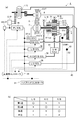
- FIG. 1 is a schematic system diagram showing a hybrid vehicle drive system and its overall control system according to a first embodiment.
- (a) is a schematic system diagram showing a drive system of the hybrid vehicle and an overall control system thereof
- (b) is a V-belt type continuously variable transmission in the drive system of the hybrid vehicle.
- FIG. 3 is a logic diagram of clutch engagement in a sub-transmission built in the machine. 3 is an example of a shift map stored in the transmission controller according to the first embodiment. It is the mode map in which the driving mode of the hybrid vehicle of Example 1 was set. It is the schematic showing the action reaction of the force in the variator of Example 1.
- 6 is a characteristic diagram showing the relationship between the action and reaction of force in the variator in FIG. 5 and the relationship between the hydraulic pressures necessary for maintaining the transmission ratio.
- 6 is a flowchart illustrating a gear ratio maintaining control process in an EV mode according to the first embodiment.
- 4 is a time chart showing details of maintaining a gear ratio during mode transition of the first embodiment.
- 6 is a time chart when hydraulic pressure is not generated in the EV mode in the hybrid vehicle of the comparative example.
- 6 is a time chart in the case where the hydraulic oil is generated by operating the electric oil pump EO / P in the EV mode in the hybrid vehicle of the first embodiment. It is a time chart at the time of performing gear ratio maintenance control including a vehicle stop.
- 3 is a flowchart illustrating an electric oil pump operation process according to the first embodiment.
- 3 is a time chart illustrating an electric oil pump operation process according to the first embodiment.
- 3 is a flowchart illustrating an electric oil pump stop process according to the first embodiment.
- 3 is a time chart illustrating an electric oil pump stop process according to the first embodiment.
- 6 is a flowchart illustrating an electric oil pump operation process according to a second embodiment.
- 6 is a time chart illustrating an electric oil pump operation process according to a second embodiment.
- 6 is a flowchart illustrating an electric oil pump stop process according to a third embodiment.
- 6 is a time chart illustrating an electric oil pump stop process according to a third embodiment.
- FIG. 10 is a schematic explanatory diagram illustrating a variator according to a sixth embodiment.
- FIG. 1 is a schematic system diagram showing a hybrid vehicle drive system and its overall control system according to the first embodiment.
- the hybrid vehicle of FIG. 1 is mounted with an engine 1 and an electric motor 2 as power sources, and the engine 1 is started by a starter motor 3.
- the engine 1 is drive-coupled to the drive wheels 5 through a V-belt type continuously variable transmission 4 so as to be appropriately separated.
- the variator CVT of the continuously variable transmission 4 is a V belt type continuously variable transmission mechanism including a primary pulley 6, a secondary pulley 7, and a V belt 8 (endless flexible member) spanned between these pulleys 6 and 7. is there.
- the V belt 8 employs a configuration in which a plurality of elements are bundled by an endless belt, but may be a chain system or the like, and is not particularly limited.
- the primary pulley 6 is coupled to the crankshaft of the engine 1 via the torque converter T / C, and the secondary pulley 7 is coupled to the drive wheel 5 via the clutch CL and the final gear set 9 in order.
- FIG. 1 conceptually shows a power transmission path.
- a high clutch H / C, a reverse brake R / B, and a low brake L / B provided in an auxiliary transmission 31 described later are collectively referred to as a clutch. It is described as CL.
- the clutch CL When the clutch CL is engaged, the power from the engine 1 is input to the primary pulley 6 via the torque converter T / C, and then sequentially passes through the V belt 8, the secondary pulley 7, the clutch CL, and the final gear set 9 to drive wheels 5 To be used for running a hybrid vehicle.
- the pulley V groove width of the primary pulley 6 is reduced while the pulley V groove width of the secondary pulley 7 is increased to increase the winding arc diameter of the V belt 8 and the primary pulley 6 and at the same time Decrease the diameter of the winding arc with pulley 7.
- the variator CVT upshifts to the high pulley ratio (high gear ratio).
- the gear ratio is set to the maximum gear ratio.
- the variator CVT downshifts to the low pulley ratio (low gear ratio).
- the gear shift is set to the minimum gear ratio.
- the variator CVT has a primary rotational speed sensor 6a for detecting the rotational speed of the primary pulley 6 and a secondary rotational speed sensor 7a for detecting the rotational speed of the secondary pulley 7, and the rotational speed detected by these both rotational speed sensors.
- the actual gear ratio is calculated based on the above, and hydraulic control of each pulley is performed so that the actual gear ratio becomes the target gear ratio.
- the electric motor 2 is always coupled to the drive wheel 5 via the final gear set 11, and the electric motor 2 is driven via the inverter 13 by the power of the battery 12.
- the inverter 13 converts the DC power of the battery 12 into AC power and supplies it to the electric motor 2, and controls the driving force and the rotation direction of the electric motor 2 by adjusting the power supplied to the electric motor 2.
- the electric motor 2 functions as a generator in addition to the motor drive described above, and is also used for regenerative braking. During this regenerative braking, the inverter 13 applies a power generation load corresponding to the regenerative braking force to the electric motor 2 so that the electric motor 2 acts as a generator, and the generated power of the electric motor 2 is stored in the battery 12.
- the clutch CL is released and the electric motor 2 is driven or regenerated while the engine 1 is stopped, so that only the power of the electric motor 2 passes through the final gear set 11 to the drive wheels 5.
- the vehicle travels in the electric travel mode (EV mode) using only the electric motor 2.
- EV mode electric travel mode
- the brake disk 14 that rotates together with the drive wheels 5 is clamped by the caliper 15 to achieve the purpose.
- the caliper 15 is connected to a master cylinder 18 that outputs a brake fluid pressure corresponding to the brake pedal depression force under a boost by a negative pressure brake booster 17 that responds to the depression force of the brake pedal 16 that the driver steps on.
- the brake disc 14 is braked by operating the caliper 15 by the brake fluid pressure generated by the master cylinder 18.
- the hybrid vehicle drives the wheel 5 with a torque according to the driving force command that the driver commands by depressing the accelerator pedal 19, and travels with the driving force according to the driver's request. .
- the hybrid controller 21 selects the travel mode of the hybrid vehicle, the output control of the engine 1, the rotational direction control and output control of the electric motor 2, the shift control of the variator CVT, the shift control of the auxiliary transmission 31, and the clutch CL.
- the fastening / release control and the charge / discharge control of the battery 12 are executed.
- the hybrid controller 21 performs these controls via the corresponding engine controller 22, motor controller 23, transmission controller 24, and battery controller 25.
- the hybrid controller 21 includes an accelerator pedal opening sensor that detects a signal from the brake switch 26, which is a normally open switch that switches from OFF to ON when the brake pedal 16 is depressed, and an accelerator pedal depression amount (accelerator pedal opening) APO.
- the signal from 27 is input.
- the hybrid controller 21 further exchanges internal information with the engine controller 22, the motor controller 23, the transmission controller 24, and the battery controller 25.
- the engine controller 22 controls the output of the engine 1 in response to a command from the hybrid controller 21, and the motor controller 23 controls the rotational direction of the electric motor 2 via the inverter 13 in response to the command from the hybrid controller 21.
- the transmission controller 24 responds to a command from the hybrid controller 21 and uses oil from a mechanical oil pump O / P driven by an engine (or an electric oil pump EO / P driven by a pump motor) as a medium.
- the shift control of the variator CVT V-belt type continuously variable transmission mechanism CVT
- the shift control of the auxiliary transmission 31, and the engagement / release control of the clutch CL are performed.
- the battery controller 25 performs charge / discharge control of the battery 12 in response to a command from the hybrid controller 21.
- FIG. 2 (a) is a schematic system diagram showing a hybrid vehicle drive system and its overall control system according to the first embodiment.
- FIG. 2 (b) is a continuously variable transmission in the hybrid vehicle drive system according to the first embodiment.
- 4 is an engagement logic diagram of a clutch CL (specifically, H / C, R / B, L / B) in the auxiliary transmission 31 built in FIG.
- the auxiliary transmission 31 rotatably supports the composite sun gears 31s-1 and 31s-2, the inner pinion 31pin, the outer pinion 31pout, the ring gear 31r, the pinion 31pin, and the flange 31pout.
- a Ravigneaux type planetary gear set comprising the carrier 31c.
- the sun gear 31s-1 is coupled to the secondary pulley 7 so as to act as an input rotating member, and the sun gear 31s-2 is arranged coaxially with respect to the secondary pulley 7, but freely rotates. To get.
- the inner pinion 31pin is engaged with the sun gear 31s-1, and the inner pinion 31pin and the sun gear 31s-2 are respectively engaged with the outer pinion 31pout.
- the outer pinion 31pout meshes with the inner periphery of the ring gear 31r, and is coupled to the final gear set 9 so that the carrier 31c acts as an output rotating member.
- the carrier 31c and the ring gear 31r can be appropriately coupled by the high clutch H / C as the clutch CL, the ring gear 31r can be appropriately fixed by the reverse brake R / B as the clutch CL, and the sun gear 31s-2 can be coupled by the clutch CL. It can be fixed as appropriate with a certain low brake L / B.
- the auxiliary transmission 31 is engaged with the high clutch H / C, the reverse brake R / B, and the low brake L / B in the combinations indicated by the circles in FIG. 2 (b), and the others are shown in FIG. 2 (b).
- the forward first speed, the second speed, and the reverse speed can be selected.
- the sub-transmission 31 is in a neutral state where no power is transmitted.
- the auxiliary transmission 31 When the transmission 31 is in the first forward speed selection (deceleration) state and the high clutch H / C is engaged, the auxiliary transmission 31 is in the second forward speed selection (direct connection) state and when the reverse brake R / B is engaged, The transmission 31 is in a reverse selection (reverse) state.
- the continuously variable transmission 4 in FIG. 2 (a) releases all the clutches CL (H / C, R / B, L / B) and puts the sub-transmission 31 in a neutral state, so that the variator CVT (secondary The pulley 7) and the drive wheel 5 can be disconnected.
- the continuously variable transmission 4 in FIG. 2 (a) is controlled by using oil from a mechanical oil pump O / P driven by an engine or an electric oil pump EO / P driven by a pump motor as a working medium.
- the transmission controller 24 includes a line pressure solenoid 35, a lockup solenoid 36, a primary pulley pressure solenoid 37-1, a secondary pulley pressure solenoid 37-2, a low brake pressure solenoid 38, a high clutch pressure & reverse brake pressure solenoid 39 and a switch.
- the control of the variator CVT is controlled through the valve 41 as follows.
- the transmission controller 24 receives a signal from the vehicle speed sensor 32 that detects the vehicle speed VSP and a signal from the acceleration sensor 33 that detects the vehicle acceleration / deceleration G.
- the line pressure solenoid 35 responds to a command from the transmission controller 24 and regulates the oil from the mechanical oil pump O / P to the line pressure PL corresponding to the vehicle required driving force.
- An electric oil pump EO / P is connected between the mechanical oil pump O / P and the line pressure solenoid 35, and pump discharge pressure is supplied in response to a command from the transmission controller 24.
- the lockup solenoid 36 responds to a lockup command from the transmission controller 24 and directs the line pressure PL to the torque converter T / C as appropriate, so that the torque converter T / C is connected between the input and output elements as required. Set to a directly connected lockup state.
- the primary pulley pressure solenoid 37-1 adjusts the line pressure PL to the primary pulley pressure in response to the CVT gear ratio command from the transmission controller 24, and supplies this to the primary pulley 6, thereby
- the CVT gear ratio command from the transmission controller 24 is realized by controlling the groove width and the V groove width of the secondary pulley 7 so that the CVT gear ratio matches the command from the transmission controller 24.
- the secondary pulley pressure solenoid 37-2 adjusts the line pressure PL to the secondary pulley pressure according to the clamping force command from the transmission controller 24, and supplies the secondary pulley pressure to the secondary pulley 7. Clamp it so that it will not slip.
- the low brake pressure solenoid 38 is engaged by supplying the line pressure PL to the low brake L / B as the low brake pressure when the transmission controller 24 issues the first speed selection command for the sub-transmission 31.
- the first speed selection command is realized.
- the high clutch pressure & reverse brake pressure solenoid 39 is a switch valve that uses the line pressure PL as the high clutch pressure & reverse brake pressure when the transmission controller 24 issues the second speed selection command or reverse selection command for the sub-transmission 31. Supply to 41.
- the maximum discharge capacity of the electric oil pump EO / P of Example 1 is set smaller than that of the mechanical oil pump O / P, and does not have the discharge capacity to shift the variator CVT.
- the motor and pump of the electric oil pump EO / P are miniaturized by ensuring the discharge capacity that maintains the ratio or the discharge capacity that supplies lubricating oil.
- the switch valve 41 uses the line pressure PL from the solenoid 39 as the high clutch pressure to the high clutch H / C, and by engaging this, the second speed selection command of the auxiliary transmission 31 is issued. Realize.
- the switch valve 41 uses the line pressure PL from the solenoid 39 as the reverse brake pressure to the reverse brake R / B and fastens it, thereby realizing the reverse selection command of the auxiliary transmission 31.
- FIG. 3 is an example of a shift map stored in the transmission controller 24 of the first embodiment.
- the transmission controller 24 controls the continuously variable transmission 4 according to the driving state of the vehicle (vehicle speed VSP, primary rotation speed Npri, accelerator pedal opening APO in the first embodiment) while referring to this shift map.
- the operating point of the continuously variable transmission 4 is defined by the vehicle speed VSP and the primary rotational speed Npri.
- the slope of the line connecting the operating point of the continuously variable transmission 4 and the zero point of the lower left corner of the transmission map is the transmission ratio of the continuously variable transmission 4 (the overall ratio obtained by multiplying the transmission ratio of the variator CVT by the transmission ratio of the sub-transmission 31 Speed ratio, hereinafter referred to as “through speed ratio”).
- the continuously variable transmission 4 When the continuously variable transmission 4 is in the low speed mode, the continuously variable transmission 4 sets the speed ratio of the variator CVT to the highest gear ratio and the variator CVT to the highest gear ratio. It is possible to shift between the resulting low speed mode highest line. At this time, the operating point of the continuously variable transmission 4 moves in the A region and the B region.
- the continuously variable transmission 4 when the continuously variable transmission 4 is in the high speed mode, the continuously variable transmission 4 sets the speed ratio of the variator CVT to the maximum high speed ratio and the speed ratio of the variator CVT obtained by setting the speed ratio of the variator CVT to the lowest speed ratio It is possible to shift between the high-speed mode highest line obtained as described above. At this time, the operating point of the continuously variable transmission 4 moves in the B region and the C region.
- the gear ratio of each gear stage of the sub-transmission 31 is such that the gear ratio corresponding to the low speed mode highest line (low speed mode highest high gear ratio) corresponds to the high speed mode lowest line (high speed mode lowest gear ratio). It is set to be smaller than that.
- the range of the through gear ratio of the continuously variable transmission 4 that can be used in the low speed mode (“low speed mode ratio range” in the figure) and the range of the through gear ratio of the continuously variable transmission 4 that can be used in the high speed mode (in the figure).
- “High-speed mode ratio range”) and the operating point of the continuously variable transmission 4 is in the B region sandwiched between the high-speed mode lowest line and the low-speed mode highest line. 4 can select either low-speed mode or high-speed mode.
- the mode switching shift line for shifting the sub-transmission 31 is set so as to overlap the low speed mode highest line.
- the through speed change ratio (hereinafter referred to as “mode change speed change ratio mRatio”) corresponding to the mode change speed change line is set to a value equal to the low speed mode maximum High speed change ratio.
- the reason why the mode switching shift line is set in this manner is that the smaller the gear ratio of the variator CVT, the smaller the input torque to the sub-transmission 31, and the lower the shift shock when shifting the sub-transmission 31. .
- the transmission controller 24 When the operating point of the continuously variable transmission 4 crosses the mode switching speed line, that is, when the actual value of the through speed ratio changes across the mode switching speed ratio mRatio, the transmission controller 24 is connected to the variator CVT. Both the sub-transmissions 31 perform coordinated shifting and switch between the high speed mode and the low speed mode.
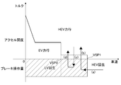
- FIG. 4 is a mode map in which the travel mode of the hybrid vehicle of the first embodiment is set.
- the value above 0 on the vertical axis is set according to the accelerator pedal opening, and the value below 0 is set according to the on / off state of the brake switch 26.
- the powering region in the EV mode is set up to the powering vehicle speed VSPX. Details of the power running speed VSPX will be described later.
- the EV mode is used up to a predetermined vehicle speed VSP1 higher than the power running speed VSPX.
- the power running area is set.
- the region below the predetermined vehicle speed VSP1 is hardly selected when the accelerator pedal 19 is depressed.
- the regeneration by the electric motor 2 is performed.
- the kinetic energy of the vehicle is converted into electric power by braking, and this is stored in the battery 12 to improve energy efficiency (HEV regeneration state).
- the engine 1 when traveling in the EV mode, the engine 1 is stopped so that the fuel injection stoppage (fuel cut) that has been performed during the coasting from the viewpoint of fuel consumption is continued even when the clutch CL is released.
- the engine 1 is stopped by prohibiting the restart of fuel injection (fuel recovery).
- the vehicle is operated to be depressed again, or when the vehicle is used mainly in a driving environment where such operation is forced, or the brake pedal 16 is depressed to decelerate.
- the EV mode is switched to the HEV mode.
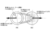
- FIG. 5 is a schematic diagram showing the action and reaction of force in the variator of the first embodiment.
- a secondary spring SEC_SPR that presses in a direction in which the secondary pulley groove width is narrowed is accommodated in the pulley chamber of the secondary pulley 7. Therefore, when the hydraulic pressure in the primary pulley 6 or the hydraulic pressure in the secondary pulley 7 drops, the secondary thrust Fsec by the secondary spring SEC_SPR becomes dominant, and a force for narrowing the secondary pulley groove width acts.
- a tension fs is generated in the V-belt 8 (hereinafter referred to as secondary tension), and a force that widens the groove width of the primary pulley 6 acts by pulling the V-belt 8 toward the secondary pulley 7 side.
- secondary tension a tension fs is generated in the V-belt 8 (hereinafter referred to as secondary tension), and a force that widens the groove width of the primary pulley 6 acts by pulling the V-belt 8 toward the secondary pulley 7 side.
- a release command is output to the clutch CL, in actuality, a slight rotation occurs in each pulley due to dragging of oil or the like. In this state, a force as shown in FIG.
- the gear ratio of the variator CVT is returned to Low, which shifts to the Low side. For example, even if each pulley is not rotating, the gear ratio of the variator CVT is shifted to the low side due to the longitudinal slip of the V-belt 8 moving radially in the pulley groove.
- the electric type when a request to switch to the EV mode (EV regeneration state) is made during deceleration in the HEV mode, the electric type is used to maintain the speed ratio of the continuously variable transmission 4 at that time as a predetermined speed ratio.
- the oil pump EO / P was activated.
- FIG. 6 is a characteristic diagram showing the relationship between the action and reaction of force in the variator in FIG. 5 and the relationship between the hydraulic pressures necessary for maintaining the transmission ratio.
- the secondary thrust Fsec is generated by the secondary spring SEC_SPR
- the secondary tension fs corresponding to the gear ratio is generated.
- the primary pulley 6 the sliding resistance between the pulley and the V-belt 8 (hereinafter referred to as a shift resistance Fr) always acts in a direction that prevents the movement of the V-belt 8.
- the set load of the secondary spring SEC_SPR is set to a magnitude that overcomes the sliding resistance Fr in all speed ratio regions.
- a predetermined hydraulic pressure is generated in the primary pulley 6 to generate the tension fp.
- the tension fp is supplied with a predetermined hydraulic pressure so that the pulley tension difference (
- the pulley tension difference can be set smaller than the speed change resistance Fr.
- the gear ratio can be maintained only by supplying a relatively low predetermined oil pressure.
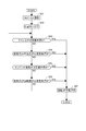
- FIG. 7 is a flowchart showing the gear ratio maintaining control process in the EV mode according to the first embodiment.
- step S1 it is determined whether the electric oil pump EO / P is operating in the EV mode, and it is not in the EV mode (HEV mode) or the electric oil pump EO / P is not operating. If it is determined that the state is reached, the process proceeds to step S10. Otherwise, the process proceeds to step S2. In step S2, it is determined whether or not there is a request to continuously select the EV mode. If the EV mode is continuously selected, the process proceeds to step S3. Otherwise, the process proceeds to step S13.
- step S3 it is determined whether the operation time of the electric oil pump EO / P is equal to or longer than a preset continuous operation allowable time (for example, 3 minutes). If the operation time is less than the continuous operation allowable time, the process proceeds to step S4. If the operating time of the electric oil pump EO / P is longer than the allowable continuous operation time, proceed to step S13 to deactivate the electric oil pump EO / P (the electric oil pump EO / P is hot) The operation of the electric oil pump EO / P is prohibited and the HEV mode is selected instead of the EV mode. In this case, the mechanical oil pump O / P operates instead of the electric oil pump EO / P. Then, the process proceeds to step S14, and the gear ratio control is performed according to the shift line set in the shift map.
- a preset continuous operation allowable time for example, 3 minutes.
- step S10 it is determined whether or not there is a request for transition to the EV mode. If there is a request for transition from the HEV mode to the EV mode, the process proceeds to step S11. Otherwise, the process proceeds to step S13 and the HEV mode is set. select. In this case, since the mechanical oil pump O / P is operating, the electric oil pump EO / P is not operated. Then, the process proceeds to step S14, and the gear ratio control is performed according to the shift line set in the shift map.
- step S11 it is determined whether the electric oil pump EO / P has been continuously operated for more than the allowable continuous operation time in the past, and is not stopped, but simply stopped in the HEV mode.
- the process proceeds to step S4, the EV mode is selected, and the operation of the electric oil pump EO / P is continued.
- the secondary pulley pressure solenoid 37-2 is closed and the opening degree of the primary pulley pressure solenoid 37-1 is controlled so that the hydraulic pressure from the electric oil pump EO / P is supplied into the secondary pulley 7.
- the gear ratio is supplied only to the primary pulley 6, and the gear ratio during the EV mode is maintained at the gear ratio when the HEV mode is switched to the EV mode (step S5).
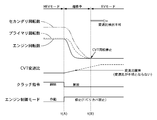
- FIG. 8 is a time chart showing details of maintaining the gear ratio during the mode transition of the first embodiment.
- the gear ratio of the variator CVT is based on the rotational speed. Can be detected. Therefore, the timing for maintaining the gear ratio or the predetermined gear ratio to be maintained may be set as appropriate while the gear ratio can be recognized during the transition from the HEV mode to the EV mode, and a mode switching command is output. It is not limited to immediately after being performed.
- step S12 whether or not a predetermined time (for example, 1 minute) required for cooling the electric oil pump EO / P has elapsed after the electric oil pump EO / P has been stopped due to operation for an allowable continuous operation time or longer. If it is determined that the electric oil pump EO / P has been operated, the electric oil pump EO / P can be operated, so proceed to step S4 to select the EV mode and operate the electric oil pump EO / P. . On the other hand, if it is determined that the required predetermined time has not elapsed, the electric oil pump EO / P cannot be operated, so the process proceeds to step S13, and even if there is a request for transition to the EV mode, the HEV mode is set.
- a predetermined time for example, 1 minute
- step S14 the gear ratio is brought into the controlled state as usual.
- the EV mode is not switched to the HEV mode, and the hydraulic pressure is always secured by the mechanical oil pump O / P, so that a pulling shock or the like does not occur.
- FIG. 9 is a time chart when no hydraulic pressure is generated in the EV mode in the hybrid vehicle of the comparative example.
- the first traveling state is a deceleration state in the HEV mode in which the accelerator pedal 19 is released and the brake pedal 16 is depressed.
- the HEV regeneration state is switched to the EV regeneration state.
- the clutch CL is released, the engine 1 is stopped, and the hydraulic pressure of the mechanical oil pump O / P becomes zero accordingly. Therefore, the gear ratio of the variator CVT gradually changes toward the lowest gear ratio (low return) by the clamping force of the secondary spring SEC_SPR.
- the driver starts depressing the accelerator pedal 19 from the deceleration state by change mind and requests acceleration.
- the accelerator pedal opening APO increases to a region where HEV power running is set in the mode map
- the EV mode (EV regeneration state) is switched to the HEV mode (HEV power running state).
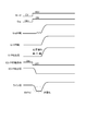
- FIG. 10 is a time chart when the hydraulic oil is generated by operating the electric oil pump EO / P in the EV mode in the hybrid vehicle of the first embodiment.
- the first traveling state is a deceleration state in the HEV mode in which the accelerator pedal 19 is released and the brake pedal 16 is depressed.
- the HEV regeneration state is switched to the EV regeneration state.
- the clutch CL is released, the engine 1 is stopped, and the hydraulic pressure of the mechanical oil pump O / P becomes zero accordingly.
- the electric oil pump EO / P is operated, a certain amount of oil pressure is secured, a predetermined oil pressure is generated in the primary pulley 6, and the gear ratio of the variator CVT is switched from the HEV mode to the EV mode. Maintain the gear ratio.
- the driver starts to depress the accelerator pedal 19 from the deceleration state by a change mind and requests acceleration.
- the accelerator pedal opening APO increases to the region where HEV power running is set in the mode map, the EV regeneration state is switched to the HEV power running state.
- the speed ratio of the variator CVT is maintained at the speed ratio when the HEV mode is switched to the EV mode. . Since the gear ratio when switching from the HEV mode to the EV mode is basically switched in the coasting state, the gear ratio along the coast line is set as shown in the gear shift map shown in FIG. Therefore, when the vehicle speed indicated by the arrow (a) in FIG. 4 is switched from the HEV mode to the EV mode, the gear ratio of the variator CVT is switched in the state of the highest gear ratio or a gear ratio higher than 1.
- the gear ratio immediately before the mode switching is close to the lowest gear ratio.
- the release condition is that “the brake pedal 16 depression time has elapsed for a predetermined time or longer (for example, 2 seconds or longer)”. Therefore, when the accelerator pedal 19 is released, the high-speed mode highest line in FIG. 3 is selected, and when the gear ratio is upshifted from near the lowest gear ratio to the highest gear ratio, the gear change time depends on the clutch release condition. Therefore, the gear ratio is shifted to the highest gear ratio or near the highest gear ratio (at least the gear ratio higher than 1), and this gear ratio is maintained.
- the target gear ratio set with the accelerator pedal 19 released is basically the highest gear ratio along the high-speed mode highest line.
- the maximum gear ratio is set to the highest gear ratio for a predetermined time (for example, 2 seconds) set in the clutch release condition when switching to the EV mode. Even if shifting is performed, shifting to the highest gear ratio may not be possible.
- the minimum gear ratio achieved at this time is defined as a predetermined gear ratio.
- the HEV mode is switched to the EV mode and the variator CVT is maintained at the predetermined gear ratio.
- the driver gently depresses the accelerator pedal 19, and the vehicle speed increases in the EV power running state of the EV mode.
- VSPX shown in the mode map of FIG. 4
- the mode is changed from the EV mode to the HEV mode.
- a switch request is output.
- the power running vehicle speed VSPX is set to a vehicle speed range in which the increased secondary rotational speed becomes a rotational speed that is equal to or higher than the output-side rotational speed of the clutch CL.
- the power running vehicle speed VSPX with the EV power running area set can avoid pulling shocks without excessively increasing the engine speed when switching to HEV mode at any gear ratio that can be maintained by the variator CVT.
- the vehicle speed can be switched to HEV mode.
- FIG. 11 is a time chart when the gear ratio maintenance control including vehicle stop is performed.
- the gear ratio is made by returning low during the EV mode and the gear is automatically shifted to the lowest gear ratio after a predetermined time has elapsed since switching to the EV mode.
- the first traveling state is a deceleration state in the HEV mode in which the accelerator pedal 19 is released and the brake pedal 16 is depressed.
- the gear ratio control or the like is not particularly performed.
- the driver starts depressing the accelerator pedal 19 and makes an acceleration request.
- the EV mode (EV regeneration state) is switched to the HEV mode (HEV power running state).
- Example 1 (Operation based on Example 1) Next, Example 1 will be described.
- the vehicle speed VSP decreases to the vehicle speed at which the EV regeneration area is set in the mode map, so the HEV mode (HEV regeneration state) is switched to the EV mode (EV regeneration state).
- the clutch CL is released, the engine 1 is stopped, and the hydraulic pressure of the mechanical oil pump O / P becomes zero accordingly.
- the electric oil pump EO / P since the electric oil pump EO / P is operated, a certain amount of oil pressure is secured, a predetermined oil pressure is generated in the primary pulley 6, and the gear ratio of the variator CVT is switched from the HEV mode to the EV mode. Maintain the gear ratio.
- the speed ratio of the variator CVT is maintained at the speed ratio when the HEV mode is switched to the EV mode. . Since the gear ratio when switching from the HEV mode to the EV mode is basically switched in the coasting state, the gear ratio along the coast line is set as shown in the gear shift map shown in FIG. Therefore, when the vehicle speed indicated by the arrow (a) in FIG. 4 is switched from the HEV mode to the EV mode, the gear ratio of the variator CVT is switched in the state of the highest gear ratio or a gear ratio higher than 1.
- the gear ratio immediately before the mode switching is close to the lowest gear ratio.
- the release condition is that “the brake pedal 16 has been depressed for more than 2 seconds”. Therefore, when the accelerator pedal 19 is released, the high-speed mode highest line in FIG. 3 is selected, and when the gear ratio is upshifted from near the lowest gear ratio to the highest gear ratio, the gear change time depends on the clutch release condition. Therefore, the gear ratio is shifted to the highest gear ratio or near the highest gear ratio (at least the gear ratio higher than 1), and this gear ratio is maintained.
- FIG. 12 is a flowchart illustrating an electric oil pump operation process according to the first embodiment.
- step S21 a request for transition from the HEV mode to the EV mode is output.
- step S22 the engine 1 is switched from ON (operating state) to OFF (stopped state). Specifically, fuel injection is stopped.
- step S23 it is determined whether or not the line pressure is less than a predetermined value. If the line pressure is less than the predetermined value, the process proceeds to step S27 to output an operation command for the electric oil pump EO / P.
- step S24 it is determined whether or not the discharge pressure of the mechanical oil pump O / P is less than a predetermined value. If the discharge pressure is less than the predetermined value, the process proceeds to step S27 and an operation command for the electric oil pump EO / P is output. In step S25, it is determined whether or not the engine speed is less than a predetermined value. If the engine speed is less than the predetermined value, the process proceeds to step S27 to output an operation command for the electric oil pump EO / P.
- step S26 it is determined whether or not the rotational speed of the mechanical oil pump O / P is less than a predetermined value, and if it is less than the predetermined value, the process proceeds to step S27 to output an operation command for the electric oil pump EO / P.
- FIG. 13 is a time chart showing the operation of the electric oil pump according to the first embodiment. That is, when operating the electric oil pump EO / P, the line pressure actually decreases, the discharge pressure of the mechanical oil pump O / P decreases, or the engine rotation that is the drive source of the mechanical oil pump O / P If either the number decreases or the rotational speed of the mechanical oil pump O / P decreases, the electric oil pump EO / P is installed to secure the hydraulic pressure to maintain the gear ratio. Judge that it should work. As a result, the electric oil pump EO / P is not driven unnecessarily, and power consumption can be suppressed.
- FIG. 14 is a flowchart illustrating the electric oil pump stop process according to the first embodiment.
- step S31 a request for transition from the EV mode to the HEV mode is output.
- step S32 the engine 1 is switched from OFF (stop state) to ON (operation state). Specifically, the starter motor is driven and fuel injection is resumed.
- step S33 it is determined whether or not the line pressure is equal to or greater than a predetermined value.
- step S37 a non-operation command for the electric oil pump EO / P is output.
- step S34 it is determined whether or not the discharge pressure of the mechanical oil pump O / P is equal to or higher than a predetermined value. If the discharge pressure is higher than the predetermined value, the process proceeds to step S37 to output a non-operation command for the electric oil pump EO / P. .
- step S35 it is determined whether or not the engine speed is greater than or equal to a predetermined value. If the engine speed is greater than or equal to the predetermined value, the process proceeds to step S37 and a non-operation command for the electric oil pump EO / P is output.
- step S36 it is determined whether or not the rotational speed of the mechanical oil pump O / P is equal to or greater than a predetermined value. If the rotational speed is equal to or greater than the predetermined value, the process proceeds to step S37 to output a non-operation command for the electric oil pump EO / P. .
- FIG. 15 is a time chart showing the electric oil pump stop process of the first embodiment.
- the line pressure is actually secured, or the discharge pressure of the mechanical oil pump O / P is secured, or the engine rotation that is the drive source of the mechanical oil pump O / P
- the gear ratio can be changed from the state where the gear ratio is maintained, and the electric oil Determine that pump EO / P should be deactivated.
- the electric oil pump EO / P is not driven unnecessarily, and power consumption can be suppressed.
- the gear ratio control that ensures responsiveness is achieved without the line pressure dropping instantaneously to zero. realizable.
- (1-1) It has an engine 1, a variator CVT (continuously variable transmission), and an electric motor 2 (drive motor).
- the drive wheel 5 A hybrid controller 24 (hereinafter referred to as a controller) that stops the engine 1 when the clutch CL is released.
- the controller maintained the gear ratio of the variator CVT when the engine 1 was stopped. Therefore, it is possible to quickly switch from the HEV mode to the EV mode, and to improve fuel efficiency.
- the gear ratio since the gear ratio is maintained, suppression of the low return does not cause an excessive increase in the engine speed, and the uncomfortable feeling given to the driver can be suppressed.
- the “when switching from the HEV mode to the EV mode” may be the switching command timing when the switching command timing from the HEV mode to the EV mode is the same as the release timing of the clutch CL.
- the gear ratio at either timing may be maintained. For example, when it is desired to shift the gear ratio to the High side to some extent from the switching command timing, it may be preferable to maintain the gear ratio at the clutch release timing.
- the variator CVT includes a primary pulley 6, a secondary pulley 7, a belt 8 (endless flexible member) bridged between both pulleys, and a secondary spring SEC_SPR that generates a clamping force of the secondary pulley 7 ( And the controller maintains the gear ratio by supplying a constant pressure to the primary pulley 6. That is, by supplying a constant pressure and utilizing the tension based on the secondary spring SEC_SPR and the sliding resistance between the belt 8 and each pulley 6, 7, the relationship between the belt and the pulley can be fixed. When operating the electric oil pump EO / P, the gear ratio can be maintained with simple control.
- the controller generates an absolute value of the difference between the secondary tension generated in the belt 8 by the secondary spring SEC_SPR and the primary tension generated in the belt 8 by a constant pressure between the pulleys 6 and 7 and the belt 8.
- a constant pressure is supplied so as to be smaller than the resistance tension generated by the sliding resistance. Therefore, the transmission ratio can be maintained by supplying the minimum required hydraulic pressure, and the discharge capacity required for the electric oil pump EO / P is reduced. Therefore, the electric oil pump EO / P can be downsized. .
- the controller determines that the line pressure of the hydraulic circuit using the mechanical oil pump O / P as a hydraulic source is less than a predetermined pressure, the discharge pressure of the mechanical oil pump O / P is less than a predetermined pressure, and the rotational speed of the engine 1
- the motor oil pump O / P is less than the predetermined rotation speed and the rotation speed of the mechanical oil pump O / P is less than the predetermined rotation speed
- the operation of the electric oil pump EO / P is started.
- the electric oil pump EO / P is not driven unnecessarily, and power consumption can be suppressed.
- the controller determines that the line pressure of the hydraulic circuit using the mechanical oil pump O / P as a hydraulic pressure is equal to or higher than the predetermined pressure, the discharge pressure of the mechanical oil pump O / P is equal to or higher than the predetermined pressure, and the rotational speed of the engine 1
- the motor oil pump O / P is more than the predetermined rotation speed and the rotation speed of the mechanical oil pump O / P is more than the predetermined rotation speed
- the operation of the electric oil pump EO / P is stopped.
- the electric oil pump EO / P is not driven unnecessarily, and power consumption can be suppressed.
- the gear ratio control that ensures responsiveness is achieved without the line pressure dropping instantaneously to zero. realizable.
- Step S11 electric oil pump operation prohibiting means for prohibiting the operation of the electric oil pump EO / P when a predetermined condition is satisfied, and the controller
- the EV mode is prohibited and the HEV mode is selected even if the EV mode should be selected.
- the EV mode is not switched to the HEV mode, and the hydraulic pressure is always secured by the mechanical oil pump O / P, so the operation of the electric oil pump EO / P cannot be obtained and the gear ratio cannot be maintained. The problem can be avoided and no pulling shock or the like occurs.
- FIG. 16 is a flowchart showing an electric oil pump operation process according to the second embodiment.
- Example 1 the actual oil pressure state in the hydraulic circuit was detected to determine the start of operation of the electric oil pump EO / P.
- the electric oil pump EO / P is immediately operated as shown in step S210, and thereafter, in step S22.
- step S210 the engine 1 is switched from ON to OFF.
- the electric oil pump EO / P is operated before the engine 1 is stopped.
- FIG. 17 is a time chart showing the operation of the electric oil pump according to the second embodiment.
- the controller activates the electric oil pump EO / P when a command to switch from the HEV mode to the EV mode is output. Therefore, since the operation of the electric oil pump EO / P can be started before the operation of the mechanical oil pump O / P stops, it is possible to avoid a situation where the line pressure is greatly reduced, and to realize stable gear ratio control. it can.
- FIG. 18 is a flowchart showing an electric oil pump stop process according to the third embodiment.
- Example 1 the actual hydraulic pressure state in the hydraulic circuit was detected to determine whether the electric oil pump EO / P was stopped.
- the electric oil pump EO / P is immediately instructed, and then The difference is that the engine 1 is switched from OFF to ON in step S32. In other words, the electric oil pump EO / P is stopped before the engine 1 is operated.
- FIG. 19 is a time chart showing the electric oil pump stop process of the third embodiment.
- the line pressure is reduced due to the delay in engine start timing and the accompanying delay in the generation of discharge pressure of the mechanical oil pump O / P.
- the electric oil pump EO / P can be quickly stopped and the power consumption can be suppressed, although there is a scene of decline.
- the controller stops the operation of the electric oil pump EO / P when a command for switching from the EV mode to the HEV mode is output. Therefore, the electric oil pump EO / P can be stopped at the start of the operation of the mechanical oil pump O / P, and wasteful power consumption can be suppressed.
- FIG. 20 is a schematic explanatory diagram illustrating a variator of Example 4 and a solenoid that performs hydraulic pressure control.
- an electric oil pump is used as a gear ratio maintaining means when maintaining the gear ratio of the variator CVT at a predetermined gear ratio.
- the transmission ratio of the variator CVT is maintained by operating the EO / P and supplying hydraulic pressure to the piston oil chamber.
- the gear ratio of the variator CVT when the engine 1 is stopped and the mechanical oil pump O / P is stopped, when maintaining the gear ratio of the variator CVT at a predetermined gear ratio, The primary pulley pressure solenoid 37-1 and the secondary pulley pressure solenoid 37-2 are fully closed to seal the piston oil chambers of the primary pulley 6 and the secondary pulley 7, thereby maintaining the gear ratio.
- the gear ratio can be maintained without providing the electric oil pump EO / P, and the cost can be reduced.
- a secondary spring SEC_SPR is provided in the secondary pulley, and this tension can be secured. Therefore, the gear ratio may be maintained by fully closing only the primary pulley pressure solenoid 37-1 so that the tension difference between the pulleys is equal to or less than the transmission resistance (see the thick line in FIG. 6).
- the piston hydraulic pressure can be increased by adding a separate control valve that can be fully closed. It is good also as sealing.
- FIG. 21 is a schematic explanatory diagram illustrating a variator and a solenoid that performs hydraulic pressure control according to the fifth embodiment.
- a primary pulley pressure solenoid is used as a gear ratio maintaining means when maintaining the gear ratio of the variator CVT at a predetermined gear ratio.
- the piston oil chambers of the primary pulley 6 and the secondary pulley 7 were sealed by fully closing the 37-1 and secondary pulley pressure solenoid 37-2, and the gear ratio was maintained.
- the oil path between the primary pulley pressure solenoid 37-1 and the primary pulley 6 and the oil path between the secondary pulley pressure solenoid 37-2 and the secondary pulley 7 are used.
- control valves 51-1 and 52-1 that can be fully closed individually and accumulators 52-1 and 52-2 are provided.
- the control valves 51-1 and 52-1 are controlled, and the hydraulic pressure is accumulated in the accumulators 52-1 and 52-2. Then, when the mode is switched to the EV mode and the engine 1 is stopped and the mechanical oil pump O / P is stopped, when maintaining the gear ratio of the variator CVT at a predetermined gear ratio, the primary pressure is used as the gear ratio maintaining means.
- the solenoid 37-1 and the secondary pressure solenoid 37-2 are fully closed to seal the piston hydraulic pressure of the primary pulley 6 and the secondary pulley 7, and the control valves 51-1 and 51-2 are opened, and the accumulator 52-1,
- the hydraulic pressure accumulated in 52-2 is supplied to the piston oil chambers of the primary pulley 6 and the secondary pulley 7. As a result, even if the sealing is incomplete and there is oil leakage, the amount of leakage can be compensated for by the accumulators 52-1, 52-2, and the gear ratio can be stably maintained at the predetermined gear ratio.
- FIG. 22 is a schematic explanatory diagram illustrating a variator according to the sixth embodiment.
- an electric oil pump is used as a gear ratio maintaining means when maintaining the gear ratio of the variator CVT at a predetermined gear ratio.
- the EO / P was activated to maintain the gear ratio of the variator CVT.
- the secondary spring SEC_SPR that generates thrust to the secondary pulley 7 but also the primary spring PRI_SPR for generating thrust to the primary pulley 6 as the gear ratio maintaining means. .
- the tension fp of the primary spring PRI_SPR is set larger than the tension fs of the secondary spring SEC_SPR, and the tension of the primary spring PRI_SPR is set so that the absolute value of the tension difference (
- the gear ratio is maintained at the predetermined gear ratio during the EV mode.
- the discharge ratio of the electric oil pump may be increased, and the gear ratio may be changed according to the traveling state even during the EV mode. .
- the speed may be changed without rotating the variator CVT.
- the variator CVT may be rotated by slip-engaging the clutch CL.
- the configuration in which the engine is restarted by the starter motor 3 is shown, but other configurations may be used.
- a vehicle with an idling stop function has been replaced by replacing the alternator with a motor / generator, adding an alternator function to the motor / generator and adding an engine start function to restart the engine from an idling stop.
- a technique for restarting the engine with this motor / generator instead of the starter motor has been put into practical use.
- the present invention may also be configured to restart the engine by the motor / generator as described above.
- the negative region on the vertical axis is determined based on ON or OFF of the brake switch 26.
- the present invention is not limited to this, and the stroke sensor of the brake pedal 16 is not limited thereto. May be determined based on the output value of the brake fluid pressure sensor, or based on the output value of a brake fluid pressure sensor that detects the master cylinder pressure or the like.
- the secondary pulley pressure solenoid 37-2 is provided.
- the secondary pulley pressure solenoid 37-2 is not provided, and the line pressure PL regulated by the line pressure solenoid 35 is used as the secondary pulley. You may make it supply directly to 7.
- the hydraulic pressure is supplied to the secondary pulley 7 as the hydraulic pressure is supplied to the primary pulley 6. Therefore, unless the discharge pressure of the electric oil pump EO / P is extremely high, the tension relationship shown in FIG. The magnitude relationship does not change), and the gear ratio can be maintained at the predetermined gear ratio as in the case of supplying hydraulic pressure only to the primary pulley 6.
Landscapes
- Engineering & Computer Science (AREA)
- Mechanical Engineering (AREA)
- Transportation (AREA)
- Chemical & Material Sciences (AREA)
- Combustion & Propulsion (AREA)
- Power Engineering (AREA)
- General Engineering & Computer Science (AREA)
- Automation & Control Theory (AREA)
- Control Of Transmission Device (AREA)
- Hybrid Electric Vehicles (AREA)
- Electric Propulsion And Braking For Vehicles (AREA)
- Control Of Vehicle Engines Or Engines For Specific Uses (AREA)
- Control Of Driving Devices And Active Controlling Of Vehicle (AREA)
Abstract
Description
2 電動モータ(動力源)
3 スタータモータ
4 Vベルト式無段変速機
5 駆動輪
6 プライマリプーリ
7 セカンダリプーリ
8 Vベルト
CVT バリエータ(無段変速機構)
T/C トルクコンバータ
9,11 ファイナルギヤ組
12 バッテリ
13 インバータ
14 ブレーキディスク
15 キャリパ
16 ブレーキペダル
17 負圧式ブレーキブースタ
18 マスタシリンダ
19 アクセルペダル
21 ハイブリッドコントローラ
22 エンジンコントローラ
23 モータコントローラ
24 変速機コントローラ
25 バッテリコントローラ
26 ブレーキスイッチ
27 アクセルペダル開度センサ
O/P オイルポンプ
31 副変速機
CL クラッチ
H/C ハイクラッチ
R/B リバースブレーキ
L/B ローブレーキ
32 車速センサ
図1は、実施例1のハイブリッド車両の駆動系およびその全体制御システムを示す概略系統図である。図1のハイブリッド車両は、エンジン1および電動モータ2を動力源として搭載され、エンジン1は、スタータモータ3により始動する。エンジン1は、Vベルト式の無段変速機4を介して駆動輪5に適宜切り離し可能に駆動結合する。
インバータ13は、バッテリ12の直流電力を交流電力に変換して電動モータ2へ供給すると共に、電動モータ2への供給電力を加減することにより、電動モータ2を駆動力制御および回転方向制御する。
なお電動モータ2は、上記のモータ駆動のほかに発電機としても機能し、回生制動の用にも供する。この回生制動時はインバータ13が、電動モータ2に回生制動力分の発電負荷をかけることにより、電動モータ2を発電機として作用させ、電動モータ2の発電電力をバッテリ12に蓄電する。
アウタピニオン31poutはリングギヤ31rの内周に噛合させ、キャリア31cを出力回転メンバとして作用するようファイナルギヤ組9に結合する。
キャリア31cとリングギヤ31rとをクラッチCLであるハイクラッチH/Cにより適宜結合可能となし、リングギヤ31rをクラッチCLであるリバースブレーキR/Bにより適宜固定可能となし、サンギヤ31s-2をクラッチCLであるローブレーキL/Bにより適宜固定可能となす。
セカンダリプーリ圧ソレノイド37-2は、変速機コントローラ24からのクランプ力指令に応じてライン圧PLをセカンダリプーリ圧に調圧し、これをセカンダリプーリ7に供給することにより、セカンダリプーリ7がVベルト8をスリップしないよう挟圧する。
ローブレーキ圧ソレノイド38は、変速機コントローラ24が副変速機31の第1速選択指令を発しているとき、ライン圧PLをローブレーキ圧としてローブレーキL/Bに供給することによりこれを締結させ、第1速選択指令を実現する。
ハイクラッチ圧&リバースブレーキ圧ソレノイド39は、変速機コントローラ24が副変速機31の第2速選択指令または後退選択指令を発しているとき、ライン圧PLをハイクラッチ圧&リバースブレーキ圧としてスイッチバルブ41に供給する。
後退選択指令時はスイッチバルブ41が、ソレノイド39からのライン圧PLをリバースブレーキ圧としてリバースブレーキR/Bに向かわせ、これを締結することで副変速機31の後退選択指令を実現する。
次に変速制御処理について説明する。図3は実施例1の変速機コントローラ24に格納される変速マップの一例である。変速機コントローラ24は、この変速マップを参照しながら、車両の運転状態(実施例1では車速VSP、プライマリ回転速度Npri、アクセルペダル開度APO)に応じて、無段変速機4を制御する。この変速マップでは、無段変速機4の動作点が車速VSPとプライマリ回転速度Npriとにより定義される。無段変速機4の動作点と変速マップ左下隅の零点を結ぶ線の傾きが無段変速機4の変速比(バリエータCVTの変速比に副変速機31の変速比を掛けて得られる全体の変速比、以下、「スルー変速比」という。)に対応する。
図4は実施例1のハイブリッド車両の走行モードが設定されたモードマップである。図4のモードマップでは、縦軸の0より上はアクセルペダル開度に応じて設定され、0より下についてはブレーキスイッチ26のオン・オフ状態に応じて設定されている。アクセルペダル19が踏み込まれたEV力行領域にあっては、力行車速VSPXまでEVモードによる力行領域が設定されている。尚、この力行車速VSPXの詳細については後述する。また、アクセルペダル19がほとんど踏み込まれていない状態(例えば、1/8よりも十分に小さなアクセルペダル開度)を表す領域には、力行車速VSPXよりも更に高車速の所定車速VSP1までEVモードによる力行領域が設定されている。この所定車速VSP1以下の領域はアクセルペダル19が踏み込まれた状態ではほとんど選択されることはない。
一方、HEVモードによる走行中にアクセルペダル19を解放してコースティング(惰性)走行へ移行した場合や、HEVモードによる力行状態からブレーキペダル16を踏み込んで車両を制動する場合、電動モータ2による回生制動によって車両の運動エネルギーを電力に変換し、これをバッテリ12に蓄電しておくことでエネルギー効率の向上を図る(HEV回生状態)。
そのため、HEVモードによる走行中に回生制動が開始され、所定車速VSP1を下回ると、クラッチCLの解放によりエンジン1およびバリエータCVTを駆動輪5から切り離してEVモードによる走行へと移行する。これによりEV回生状態とし、エンジン1および無段変速機4によるフリクションを低減し、その分だけエネルギー回生量を稼げるようにする。
次に、EVモードにおける変速比維持について説明する。例えば図4のモードマップ内に記載された矢印(a)に示すように、HEV回生領域からブレーキ操作によって減速し、EV回生領域に入ることでEV回生状態となると、クラッチCLを解放し、エンジン1を停止させる。その後、図4の矢印(b)に示すように、アクセルペダル19を踏み込むことで要求駆動力が所定以上となると、HEV力行領域に移行する。同様に、例えば図4の矢印(c)に示すように、アクセルペダル19が踏みこまれたHEV力行領域からブレーキ操作によってEV回生領域に入ることでEV回生状態となると、クラッチCLを解放し、エンジン1を停止させる。その後、図4の矢印(d)に示すように、アクセルペダル19を踏み込むことで要求駆動力が所定以上となると、HEV力行領域に移行する。このときは、エンジン1をスタータモータ3により再始動させると共に、クラッチCLを締結してEVモードからHEVモードへ切り替える。
よって、プライマリプーリ6内の油圧やセカンダリプーリ7内の油圧が抜け落ちると、セカンダリスプリングSEC_SPRによるセカンダリ推力Fsecが支配的となり、セカンダリプーリ溝幅を狭くする力が作用する。これに伴ってVベルト8に張力fsが発生し(以下、セカンダリ張力と記載する。)、Vベルト8がセカンダリプーリ7側に引っ張られることでプライマリプーリ6の溝幅が広くなる力が作用する。
基本的に、クラッチCLは解放指令が出力されているものの、実際には油等の引き摺りが発生することで、各プーリに微小回転が生じており、この状態で図5に示すような力が作用すると、バリエータCVTの変速比はLow側に変速するLow戻りが生じる。例え、各プーリが回転していない場合であっても、Vベルト8がプーリ溝内を径方向に移動する縦滑りによって、やはりバリエータCVTの変速比はLow側に変速する。
ここで、HEVモードからEVモードへの切り替え時に所定変速比に維持する方法について説明する。図6は図5のバリエータにおける力の作用反作用の関係と、変速比維持に必要な油圧の関係とを表す特性図である。セカンダリスプリングSEC_SPRによってセカンダリ推力Fsecが発生すると、変速比に応じたセカンダリ張力fsが発生する。このとき、プライマリプーリ6に着目すると、プーリとVベルト8との摺動抵抗(以下、変速抵抗Frと記載する。)がVベルト8の移動を妨げる方向に常時作用する。
セカンダリスプリングSEC_SPRのセット荷重は、全ての変速比領域において摺動抵抗Frに打ち勝つ大きさに設定されている。このとき、プライマリプーリ6に所定の油圧を発生させて張力fpを発生させる。この張力fpの大きさは、プーリ間張力差(|fs-fp|)が変速抵抗Frよりも小さくなる値となるように所定の油圧を供給する。例えば、図6の太い実線に示すように、どの変速比領域においてもセカンダリスプリングSEC_SPRの取り得る張力範囲内となるような値を設定すると、プーリ間張力差は変速抵抗Frより小さく設定できるため、比較的低い所定油圧を供給するだけで変速比を維持することができる。
図7は実施例1のEVモードにおける変速比維持制御処理を表すフローチャートである。
ステップS1では、EVモード中で、かつ、電動式オイルポンプEO/Pが作動中か否かを判断し、EVモードではない(HEVモードである)、もしくは電動式オイルポンプEO/Pが非作動状態と判断した場合はステップS10に進み、それ以外の場合はステップS2に進む。
ステップS2では、EVモードを継続的に選択する要求が有るか否かを判断し、継続的にEVモードを選択する場合はステップS3に進み、それ以外の場合はステップS13に進む。
上記フローチャートに基づく作用について説明する。まず、減速中にHEVモードからEVモードに切り替えられ、その後、車両停止することなく途中でアクセルペダル19が踏みこまれ(チェンジマインド)、再度HEVモードに切り替えられる場面について説明する。
(比較例に基づく作用)
比較例として電動式オイルポンプEO/Pを常時非作動の場合、もしくは電動式オイルポンプEO/Pを備えていないユニットの場合に、HEVモードからEVモードに遷移した後、チェンジマインドによりHEVモードに遷移した場合の問題について説明する。図9は比較例のハイブリッド車両においてEVモード時に油圧が発生しない場合におけるタイムチャートである。最初の走行状態は、アクセルペダル19を解放し、ブレーキペダル16を踏み込んだHEVモードにおける減速状態である。
次に、実施例1について説明する。図10は実施例1のハイブリッド車両においてEVモード時に電動式オイルポンプEO/Pを作動させて油圧を発生させる場合におけるタイムチャートである。最初の走行状態は、アクセルペダル19を解放し、ブレーキペダル16を踏み込んだHEVモードにおける減速状態である。
図11は車両停止を含む変速比維持制御を行った場合のタイムチャートである。ここでは、比較例としてEVモード中はLow戻りによるできなりの変速比とし、EVモードに切り替えられてから所定時間が経過すると、自動的に最Low変速比まで変速するものを例示する。
最初の走行状態は、アクセルペダル19を解放し、ブレーキペダル16を踏み込んだHEVモードにおける減速状態である。
次に、実施例1について説明する。
時刻t11において、車速VSPがモードマップにおいてEV回生領域が設定された車速まで低下するため、HEVモード(HEV回生状態)からEVモード(EV回生状態)に切り替えられる。これにより、クラッチCLは解放され、エンジン1は停止し、それに伴って機械式オイルポンプO/Pの油圧も0となる。このとき、電動式オイルポンプEO/Pを作動させるため、ある程度の油圧が確保され、プライマリプーリ6に所定の油圧を発生させて、バリエータCVTの変速比をHEVモードからEVモードに切り替えたときの変速比に維持する。
次に、HEVモードからEVモードへの切り替え要求があり、電動式オイルポンプEO/Pを作動する際の作動処理について説明する。図12は実施例1の電動式オイルポンプ作動処理を表すフローチャートである。
ステップS21では、HEVモードからEVモードへの遷移要求を出力する。
ステップS22では、エンジン1をON(作動状態)からOFF(停止状態)に切り替える。具体的には、燃料噴射を停止する。
ステップS23では、ライン圧が所定値未満か否かを判断し、所定値未満のときはステップS27に進んで電動式オイルポンプEO/Pの作動指令を出力する。
ステップS24では、機械式オイルポンプO/Pの吐出圧が所定値未満か否かを判断し、所定値未満のときはステップS27に進んで電動式オイルポンプEO/Pの作動指令を出力する。
ステップS25では、エンジン回転数が所定値未満か否かを判断し、所定値未満のときはステップS27に進んで電動式オイルポンプEO/Pの作動指令を出力する。
ステップS26では、機械式オイルポンプO/Pの回転数が所定値未満か否かを判断し、所定値未満のときはステップS27に進んで電動式オイルポンプEO/Pの作動指令を出力する。
次に、EVモードからHEVモードへの切り替え要求があり、電動式オイルポンプEO/Pを停止する際の停止処理について説明する。図14は実施例1の電動式オイルポンプ停止処理を表すフローチャートである。
ステップS31では、EVモードからHEVモードへの遷移要求を出力する。
ステップS32では、エンジン1をOFF(停止状態)からON(作動状態)に切り替える。具体的には、スタータモータを駆動し、燃料噴射を再開する。
ステップS33では、ライン圧が所定値以上か否かを判断し、所定値以上のときはステップS37に進んで電動式オイルポンプEO/Pの非作動指令を出力する。
ステップS34では、機械式オイルポンプO/Pの吐出圧が所定値以上か否かを判断し、所定値以上のときはステップS37に進んで電動式オイルポンプEO/Pの非作動指令を出力する。
ステップS35では、エンジン回転数が所定値以上か否かを判断し、所定値以上のときはステップS37に進んで電動式オイルポンプEO/Pの非作動指令を出力する。
ステップS36では、機械式オイルポンプO/Pの回転数が所定値以上か否かを判断し、所定値以上のときはステップS37に進んで電動式オイルポンプEO/Pの非作動指令を出力する。
(1-1)エンジン1とバリエータCVT(無段変速機)と電動モータ2(駆動用モータ)とを有し、電動モータ2で駆動輪5を駆動もしくは回生制動しているときに駆動輪5とバリエータCVTとの間を解放可能なクラッチCLを設けたハイブリッド車両において、クラッチCLを解放しているときにエンジン1を停止するハイブリッドコントローラ24(以下、コントローラと記載する。)と、を備え、コントローラは、エンジン1を停止しているときにバリエータCVTの変速比を維持することとした。
よって、HEVモードからEVモードに素早く切り替えることができ、燃費の改善を図ることができる。また、EVモードからHEVモードに切り替える際にも、変速比を維持しているため、Low戻りの抑制により過度のエンジン回転数上昇を招くことがなく、運転者に与える違和感を抑制できる。
よって、HEVモードからEVモードに素早く切り替えることができ、燃費の改善を図ることができる。また、EVモードからHEVモードに切り替える際にも、変速比が最Low側に変速していないため、過度のエンジン回転数上昇を招くことがなく、運転者に与える違和感を抑制できる。また、クラッチCLの入力側回転数が出力側回転数よりも高い状態を維持できるため、クラッチCLの締結による引きショック等を回避しつつ素早いモード切り替えを達成できる。また、必要な油圧を最小限に抑えることができ、安価で小型な電動式オイルポンプEO/Pを採用できる。尚、「HEVモードからEVモードに切り替えたとき」とは、HEVモードからEVモードへの切り替え指令タイミングとクラッチCLの解放タイミングとが同じ場合は切り替え指令タイミングでよい。切り替え指令タイミングより後にクラッチCLが解放される場合には、どちらかのタイミングの変速比を維持することとすればよい。例えば、切り替え指令タイミングからある程度変速比をHigh側に変速したい場合には、クラッチ解放タイミングにおける変速比を維持することが好ましい場合がある。
すなわち、一定圧を供給し、セカンダリスプリングSEC_SPRに基づく張力と、ベルト8と各プーリ6,7との間の摺動抵抗とを利用することでベルトとプーリとの関係を固定することができるため、電動式オイルポンプEO/Pを作動させる際、簡単な制御で変速比を維持することができる。
よって、必要最低限の油圧供給により変速比を維持することができ、電動式オイルポンプEO/Pに要求する吐出能力が小さくなるため、電動式オイルポンプEO/Pの小型化を図ることができる。
すなわち、車両が停車するとき、停車後の発進性を考慮してバリエータCVTの変速比を最Low変速比に戻しておくことが一般的である。しかしながら、EVモードによる発進前に最Low変速比に戻してしまうと、EVモードで発進した後、車速が上昇してEVモードからHEVモードへの切り替えが行われる際、対応するクラッチCLを締結すると、エンジン回転数の上昇によってセカンダリ回転数がクラッチCLの出力側回転数よりも低い状態となり、クラッチCLの締結によってエンジン回転数が過剰に吹き上がることで、運転者に違和感を与えるおそれがある。
これに対し、HEVモードからEVモードへの切り替え時の変速比を維持しておくことで、セカンダリ回転数がクラッチCLの出力側回転数より高い状態から完全締結状態に移行することができ、駆動輪には引きショックが発生することがない。すなわち、運転者はアクセルペダル19を踏み込んで加速要求をすると、エンジン回転数が過剰に吹け上がることなく、引きショックが生じることもないままHEVモードに切り替えられる。尚、クラッチCLの締結時にバリエータCVTにダウンシフトが必要な場合には、変速制御によりダウンシフトを実行しながらクラッチCLを締結することで、運転者の要求駆動力を達成できる。
これにより、電動式オイルポンプEO/Pが不要に駆動されることがなく、電力消費を抑制できる。
これにより、電動式オイルポンプEO/Pが不要に駆動されることがなく、電力消費を抑制できる。また、油圧が確保された状態で電動式オイルポンプEO/Pに非作動指令を出力するため、ライン圧が瞬間的に0まで低下するようなことがなく、応答性を確保した変速比制御を実現できる。
これにより、EVモードからHEVモードに切り替えられることがなくなり、機械式オイルポンプO/Pによって常に油圧は確保されるため、電動式オイルポンプEO/Pの作動が得られず変速比を維持できないといった問題を回避することができ、引きショック等を発生することがない。
次に、実施例2について説明する。基本的な構成は実施例1と同じであるため、異なる点についてのみ説明する。図16は実施例2の電動式オイルポンプ作動処理を表すフローチャートである。実施例1では、実際の油圧回路内の油圧状態を検知して電動式オイルポンプEO/Pの作動開始を判断した。これに対し、実施例2ではHEVモードからEVモードへの遷移要求が有った場合には、ステップS210に示すように、即座に電動式オイルポンプEO/Pの作動を行い、その後、ステップS22にてエンジン1をONからOFFに切り替える点が異なる。言い換えると、エンジン1の停止前に電動式オイルポンプEO/Pを作動する。
(9-7)コントローラは、HEVモードからEVモードへの切り替え指令が出力されたときに電動式オイルポンプEO/Pを作動させることとした。
よって、機械式オイルポンプO/Pの作動が停止する前に電動式オイルポンプEO/Pの作動を開始できるため、ライン圧が大きく低下するような事態を回避でき、安定した変速比制御を実現できる。
次に、実施例3について説明する。基本的な構成は実施例1と同じであるため、異なる点についてのみ説明する。図18は実施例3の電動式オイルポンプ停止処理を表すフローチャートである。実施例1では、実際の油圧回路内の油圧状態を検知して電動式オイルポンプEO/Pの停止を判断した。これに対し、実施例3ではEVモードからHEVモードへの遷移要求が有った場合には、ステップS310に示すように、即座に電動式オイルポンプEO/Pの非作動指令を行い、その後、ステップS32にてエンジン1をOFFからONに切り替える点が異なる。言い換えると、エンジン1の作動前に電動式オイルポンプEO/Pを停止する。
(10-8)コントローラは、EVモードからHEVモードへの切り替え指令が出力されたときに電動式オイルポンプEO/Pの作動を停止することとした。
よって、機械式オイルポンプO/Pの作動開始に合わせて電動式オイルポンプEO/Pを停止することができ、無駄な電力消費を抑制できる。
次に、実施例4について説明する。基本的な構成は実施例1と同じであるため、異なる点についてのみ説明する。図20は実施例4のバリエータと油圧制御を行うソレノイドを表す概略説明図である。実施例1では、エンジン1が停止して機械式オイルポンプO/Pが停止しているときに、バリエータCVTの変速比を所定変速比に維持する際、変速比維持手段として、電動式オイルポンプEO/Pを作動させてピストン油室に油圧を供給することでバリエータCVTの変速比を維持することとした。これに対し、実施例4では、エンジン1が停止して機械式オイルポンプO/Pが停止しているときに、バリエータCVTの変速比を所定変速比に維持する際、変速比維持手段として、プライマリプーリ圧ソレノイド37-1及びセカンダリプーリ圧ソレノイド37-2を全閉にしてプライマリプーリ6及びセカンダリプーリ7のピストン油室を密封し、変速比を維持するものである。これにより、電動式オイルポンプEO/Pを備えることなく変速比を維持することができ、低コスト化を図ることができる。
次に、実施例5について説明する。基本的な構成は実施例4と同じであるため、異なる点についてのみ説明する。図21は実施例5のバリエータと油圧制御を行うソレノイドを表す概略説明図である。実施例4では、エンジン1が停止して機械式オイルポンプO/Pが停止しているときに、バリエータCVTの変速比を所定変速比に維持する際、変速比維持手段として、プライマリプーリ圧ソレノイド37-1及びセカンダリプーリ圧ソレノイド37-2を全閉にしてプライマリプーリ6及びセカンダリプーリ7のピストン油室を密封し、変速比を維持した。これに対し、実施例5では、変速比維持手段として、プライマリプーリ圧ソレノイド37-1とプライマリプーリ6との間の油路上及びセカンダリプーリ圧ソレノイド37-2とセカンダリプーリ7との間の油路上に、それぞれ個別に全閉可能な制御弁51-1,52-1と、アキュムレータ52-1,52-2を設けた点が異なる。
次に、実施例6について説明する。基本的な構成は実施例1と同じであるため、異なる点についてのみ説明する。図22は実施例6のバリエータを表す概略説明図である。実施例1では、エンジン1が停止して機械式オイルポンプO/Pが停止しているときに、バリエータCVTの変速比を所定変速比に維持する際、変速比維持手段として、電動式オイルポンプEO/Pを作動させてバリエータCVTの変速比を維持することとした。これに対し、実施例6では、変速比維持手段として、セカンダリプーリ7に推力を発生させるセカンダリスプリングSEC_SPRだけでなく、プライマリプーリ6にも推力を発生させるためのプライマリスプリングPRI_SPRを備えたものである。
以上、本願発明を各実施例に基づいて説明したが、上記構成に限られず、他の構成であっても本願発明に含まれる。
実施例では、EVモード中に変速比を所定変速比に維持することとしたが、電動式オイルポンプの吐出能力を高め、EVモード中も変速比を走行状態に応じて変更する構成としてもよい。この場合、バリエータCVTを回転させることなく変速させてもよいし、バリエータCVTを回転する必要がある場合は、クラッチCLをスリップ締結することでバリエータCVTを回転させてもよい。
この場合、図7のステップS5にて変速比を所定変速比に維持する際、プライマリプーリ6内に油圧を供給することに伴いセカンダリプーリ7内にも油圧が供給されることになるが、一般的にセカンダリプーリの受圧面積<プライマリプーリの受圧面積として設定されるため、電動式オイルポンプEO/Pの吐出圧が極端に大きくない限り、図6に示した張力の関係は成立し(張力の大小関係が変わることはない)、プライマリプーリ6内にのみ油圧を供給する場合と同様に変速比を所定変速比に維持することができる。
Claims (10)
- エンジンと無段変速機と駆動用モータとを有し、駆動用モータで駆動輪を駆動もしくは回生制動しているときに駆動輪と無段変速機との間を解放可能なクラッチを設けたハイブリッド車両において、
前記クラッチを解放しているときに前記エンジンを停止するエンジン停止手段と、
該エンジン停止手段が前記エンジンを停止しているときに前記無段変速機の変速比を維持する変速比維持手段と、
を設けたことを特徴とするハイブリッド車両。 - 請求項1に記載のハイブリッド車両において、
前記エンジンに駆動され前記無段変速機に油圧を供給する機械式オイルポンプを備え、
前記変速比維持手段は、前記エンジン停止手段が前記エンジンを停止しているときは、電動モータで駆動される電動式オイルポンプにより前記無段変速機に油圧を供給して前記無段変速機の変速比を維持することを特徴とするハイブリッド車両。 - 請求項2に記載のハイブリッド車両において、
前記無段変速機は、プライマリプーリと、セカンダリプーリと、両プーリ間に架け渡された無端可撓部材と、前記セカンダリプーリのクランプ力を発生させる弾性体と、を有し、
前記変速比維持手段は、前記プライマリプーリに一定圧を供給することで変速比を維持することを特徴とするハイブリッド車両。 - 請求項3に記載のハイブリッド車両において、
前記変速比維持手段は、前記弾性体により前記無端可撓部材に生じるセカンダリ張力と、前記一定圧により前記無端可撓部材に生じるプライマリ張力との差の絶対値が、前記各プーリと前記無端可撓部材との間に生じる摺動抵抗により生じる抵抗張力よりも小さくなるように前記一定圧を供給することを特徴とするハイブリッド車両。 - 請求項2ないし4いずれか1つに記載のハイブリッド車両において、
前記エンジンを停止したまま停車したときは、停車中も前記維持された変速比の維持を継続することを特徴とするハイブリッド車両。 - 請求項1ないし5いずれか1つに記載のハイブリッド車両において、
前記機械式オイルポンプを油圧源とする油圧回路のライン圧が所定圧未満、前記機械式オイルポンプの吐出圧が所定圧未満、前記エンジンの回転数が所定回転数未満、前記機械式オイルポンプの回転数が所定回転数未満のいずれか1つが成立したときは、前記電動式オイルポンプの作動を開始することを特徴とするハイブリッド車両。 - 請求項1ないし5いずれか1つに記載のハイブリッド車両において、
前記エンジンで走行するハイブリッド走行モードから、前記エンジンを停止して前記駆動用モータで駆動輪を駆動もしくは回生制動する電気走行モードへの切り替え指令が出力されたときに前記電動式オイルポンプを作動させることを特徴とするハイブリッド車両。 - 請求項1ないし7いずれか1つに記載のハイブリッド車両において、
前記制御手段は、前記電気走行モードから前記ハイブリッド走行モードへの切り替え指令が出力されたときに前記電動式オイルポンプの作動を停止することを特徴とするハイブリッド車両。 - 請求項1ないし7いずれか1つに記載のハイブリッド車両において、
前記制御手段は、前記機械式オイルポンプを油圧源とする油圧回路のライン圧が所定圧以上、前記機械式オイルポンプの吐出圧が所定圧以上、前記エンジンの回転数が所定回転数以上、前記機械式オイルポンプの回転数が所定回転数以上のいずれか1つが成立したときは、前記電動式オイルポンプの作動を停止することを特徴とするハイブリッド車両。 - 請求項1ないし9いずれか1つに記載のハイブリッド車両において、
所定の条件が成立した時は、前記電動式オイルポンプの作動を禁止する電動式オイルポンプ作動禁止手段を有し、
前記電動式オイルポンプの作動が禁止されているときは、前記駆動用モータで駆動輪を駆動もしくは回生制動する電気走行モードを選択すべき運転状態であっても前記電気走行モードを禁止して前記エンジンで走行するハイブリッド走行モードを選択することを特徴とするハイブリッド車両。
Priority Applications (5)
| Application Number | Priority Date | Filing Date | Title |
|---|---|---|---|
| EP14767881.7A EP2977283B1 (en) | 2013-03-21 | 2014-03-14 | Hybrid vehicle |
| KR1020157025546A KR101712760B1 (ko) | 2013-03-21 | 2014-03-14 | 하이브리드 차량 |
| JP2015506741A JP5955455B2 (ja) | 2013-03-21 | 2014-03-14 | ハイブリッド車両 |
| US14/770,485 US9616883B2 (en) | 2013-03-21 | 2014-03-14 | Hybrid vehicle |
| CN201480017069.3A CN105050844B (zh) | 2013-03-21 | 2014-03-14 | 混合动力车辆 |
Applications Claiming Priority (2)
| Application Number | Priority Date | Filing Date | Title |
|---|---|---|---|
| JP2013-057519 | 2013-03-21 | ||
| JP2013057519 | 2013-03-21 |
Publications (1)
| Publication Number | Publication Date |
|---|---|
| WO2014148376A1 true WO2014148376A1 (ja) | 2014-09-25 |
Family
ID=51580062
Family Applications (1)
| Application Number | Title | Priority Date | Filing Date |
|---|---|---|---|
| PCT/JP2014/056871 Ceased WO2014148376A1 (ja) | 2013-03-21 | 2014-03-14 | ハイブリッド車両 |
Country Status (6)
| Country | Link |
|---|---|
| US (1) | US9616883B2 (ja) |
| EP (1) | EP2977283B1 (ja) |
| JP (1) | JP5955455B2 (ja) |
| KR (1) | KR101712760B1 (ja) |
| CN (1) | CN105050844B (ja) |
| WO (1) | WO2014148376A1 (ja) |
Cited By (6)
| Publication number | Priority date | Publication date | Assignee | Title |
|---|---|---|---|---|
| CN105584373A (zh) * | 2014-11-12 | 2016-05-18 | 现代自动车株式会社 | 用于确定再生制动量的方法 |
| CN106256626A (zh) * | 2015-06-16 | 2016-12-28 | 丰田自动车株式会社 | 车辆控制装置 |
| KR101811139B1 (ko) | 2015-08-28 | 2017-12-20 | 도요타지도샤가부시키가이샤 | 동력 전달 장치 |
| JP2018052148A (ja) * | 2016-09-26 | 2018-04-05 | 株式会社Subaru | ハイブリッド車両の制御装置 |
| JP2021130372A (ja) * | 2020-02-19 | 2021-09-09 | 株式会社Subaru | ハイブリッド車両システム |
| JP7618480B2 (ja) | 2021-03-30 | 2025-01-21 | 本田技研工業株式会社 | 車両用オイルポンプの駆動装置 |
Families Citing this family (18)
| Publication number | Priority date | Publication date | Assignee | Title |
|---|---|---|---|---|
| JP5924315B2 (ja) * | 2013-08-08 | 2016-05-25 | トヨタ自動車株式会社 | 車両の制御装置 |
| DE102014016172A1 (de) * | 2014-11-03 | 2016-05-04 | Audi Ag | Antriebsvorrichtung für ein hybridgetriebenes Kraftfahrzeug |
| JP6410648B2 (ja) * | 2015-03-26 | 2018-10-24 | ジヤトコ株式会社 | 車両用油圧制御装置 |
| US9616881B2 (en) * | 2015-05-22 | 2017-04-11 | Ford Global Technologies, Llc | System and method of controlling a powertrain |
| KR101664704B1 (ko) * | 2015-06-16 | 2016-10-10 | 현대자동차주식회사 | 하이브리드 차량의 엔진클러치 제어장치 및 제어방법 |
| KR101688334B1 (ko) * | 2015-12-29 | 2017-01-02 | 한국과학기술원 | 다중모드를 구비한 하이브리드 자동차용 구동장치 |
| US10054205B2 (en) * | 2016-03-15 | 2018-08-21 | GM Global Technology Operations LLC | Torque inline hydraulic pump for CVTs |
| FR3051031B1 (fr) * | 2016-05-09 | 2020-01-24 | Renault S.A.S. | Dispositif de synchronisation d'un pignon sur un arbre de boite de vitesses en mode regeneratif, procede et vehicule automobile correspondants |
| NL1041928B1 (en) * | 2016-06-14 | 2017-12-21 | Bosch Gmbh Robert | Method for operating a continuously variable transmission in a motor vehicle equipped therewith |
| WO2018096604A1 (ja) * | 2016-11-24 | 2018-05-31 | 日産自動車株式会社 | ハイブリッド車両の制御方法と制御装置 |
| KR20180067262A (ko) * | 2016-12-12 | 2018-06-20 | 현대자동차주식회사 | 하이브리드 차량의 주행 제어 장치 및 방법 |
| WO2018234985A1 (en) * | 2017-06-20 | 2018-12-27 | Tvs Motor Company Limited | Drive system for a two-wheeled vehicle |
| CN109654186B (zh) * | 2017-10-12 | 2022-03-22 | 上海汽车集团股份有限公司 | 重刹车工况下无极变速器的速比控制方法 |
| JP2019166940A (ja) * | 2018-03-23 | 2019-10-03 | 本田技研工業株式会社 | ハイブリッド車両の駆動装置 |
| KR20200018925A (ko) * | 2018-08-13 | 2020-02-21 | 현대자동차주식회사 | 하이브리드 차량의 운행모드확장방법 및 운행모드확장 시스템 |
| JP7406343B2 (ja) * | 2019-10-24 | 2023-12-27 | 株式会社Subaru | 車両 |
| JP7518715B2 (ja) * | 2020-09-29 | 2024-07-18 | 株式会社Subaru | 車両用制御装置 |
| CN112498085A (zh) * | 2020-12-18 | 2021-03-16 | 浙江万里扬股份有限公司 | 混合动力装置和车辆 |
Citations (4)
| Publication number | Priority date | Publication date | Assignee | Title |
|---|---|---|---|---|
| JP2000199442A (ja) | 1998-12-28 | 2000-07-18 | Honda Motor Co Ltd | ハイブリッド自動車 |
| JP2000230442A (ja) * | 1999-02-08 | 2000-08-22 | Toyota Motor Corp | 動力伝達装置 |
| JP2011208689A (ja) * | 2010-03-29 | 2011-10-20 | Toyota Motor Corp | 変速機の制御装置 |
| JP2012250602A (ja) * | 2011-06-02 | 2012-12-20 | Fuji Heavy Ind Ltd | ハイブリッド車両の制御装置 |
Family Cites Families (6)
| Publication number | Priority date | Publication date | Assignee | Title |
|---|---|---|---|---|
| JP3624656B2 (ja) * | 1997-10-29 | 2005-03-02 | 日産自動車株式会社 | エンジン自動停止車両の油圧制御装置 |
| US6638022B2 (en) | 2000-01-17 | 2003-10-28 | Honda Giken Kogyo Kabushiki Kaisha | Hybrid vehicle control device |
| JP4063295B2 (ja) * | 2005-10-26 | 2008-03-19 | トヨタ自動車株式会社 | ハイブリッド車用駆動装置の制御装置 |
| JP5116789B2 (ja) * | 2010-03-09 | 2013-01-09 | ジヤトコ株式会社 | 変速機の油圧制御装置およびその制御方法 |
| JP5701150B2 (ja) * | 2011-05-26 | 2015-04-15 | 富士重工業株式会社 | ハイブリッド車両の制御装置 |
| JP2013032119A (ja) * | 2011-08-02 | 2013-02-14 | Honda Motor Co Ltd | ハイブリッド駆動装置 |
-
2014
- 2014-03-14 KR KR1020157025546A patent/KR101712760B1/ko not_active Expired - Fee Related
- 2014-03-14 JP JP2015506741A patent/JP5955455B2/ja not_active Expired - Fee Related
- 2014-03-14 EP EP14767881.7A patent/EP2977283B1/en active Active
- 2014-03-14 CN CN201480017069.3A patent/CN105050844B/zh active Active
- 2014-03-14 US US14/770,485 patent/US9616883B2/en active Active
- 2014-03-14 WO PCT/JP2014/056871 patent/WO2014148376A1/ja not_active Ceased
Patent Citations (4)
| Publication number | Priority date | Publication date | Assignee | Title |
|---|---|---|---|---|
| JP2000199442A (ja) | 1998-12-28 | 2000-07-18 | Honda Motor Co Ltd | ハイブリッド自動車 |
| JP2000230442A (ja) * | 1999-02-08 | 2000-08-22 | Toyota Motor Corp | 動力伝達装置 |
| JP2011208689A (ja) * | 2010-03-29 | 2011-10-20 | Toyota Motor Corp | 変速機の制御装置 |
| JP2012250602A (ja) * | 2011-06-02 | 2012-12-20 | Fuji Heavy Ind Ltd | ハイブリッド車両の制御装置 |
Non-Patent Citations (1)
| Title |
|---|
| See also references of EP2977283A4 |
Cited By (9)
| Publication number | Priority date | Publication date | Assignee | Title |
|---|---|---|---|---|
| CN105584373A (zh) * | 2014-11-12 | 2016-05-18 | 现代自动车株式会社 | 用于确定再生制动量的方法 |
| CN106256626A (zh) * | 2015-06-16 | 2016-12-28 | 丰田自动车株式会社 | 车辆控制装置 |
| JP2017007369A (ja) * | 2015-06-16 | 2017-01-12 | トヨタ自動車株式会社 | 車両制御装置 |
| US10196061B2 (en) | 2015-06-16 | 2019-02-05 | Toyota Jidosha Kabushiki Kaisha | Control system of vehicle |
| KR101811139B1 (ko) | 2015-08-28 | 2017-12-20 | 도요타지도샤가부시키가이샤 | 동력 전달 장치 |
| JP2018052148A (ja) * | 2016-09-26 | 2018-04-05 | 株式会社Subaru | ハイブリッド車両の制御装置 |
| JP2021130372A (ja) * | 2020-02-19 | 2021-09-09 | 株式会社Subaru | ハイブリッド車両システム |
| JP7436234B2 (ja) | 2020-02-19 | 2024-02-21 | 株式会社Subaru | ハイブリッド車両システム |
| JP7618480B2 (ja) | 2021-03-30 | 2025-01-21 | 本田技研工業株式会社 | 車両用オイルポンプの駆動装置 |
Also Published As
| Publication number | Publication date |
|---|---|
| EP2977283A1 (en) | 2016-01-27 |
| JPWO2014148376A1 (ja) | 2017-02-16 |
| CN105050844A (zh) | 2015-11-11 |
| EP2977283B1 (en) | 2022-09-07 |
| JP5955455B2 (ja) | 2016-07-20 |
| KR101712760B1 (ko) | 2017-03-06 |
| US9616883B2 (en) | 2017-04-11 |
| EP2977283A4 (en) | 2017-01-11 |
| KR20150120455A (ko) | 2015-10-27 |
| CN105050844B (zh) | 2017-09-12 |
| US20160009273A1 (en) | 2016-01-14 |
Similar Documents
| Publication | Publication Date | Title |
|---|---|---|
| JP5955455B2 (ja) | ハイブリッド車両 | |
| JP6113910B2 (ja) | ハイブリッド車両の制御装置 | |
| JP5936703B2 (ja) | ハイブリッド車両のモード切り替え制御装置 | |
| JP5835500B2 (ja) | ハイブリッド車両の制御装置 | |
| JP6052775B2 (ja) | ハイブリッド車両の制御装置 | |
| US9758158B2 (en) | Hybrid vehicle control device | |
| JP6025628B2 (ja) | ハイブリッド車両の制御装置 | |
| JP2015134508A (ja) | ハイブリッド車両の電気走行減速時変速制御装置 | |
| JP6569095B2 (ja) | ハイブリッド車両の制御装置 | |
| JP6340605B2 (ja) | ハイブリッド車両の制御装置 | |
| JP6303665B2 (ja) | ハイブリッド車両の制御装置 | |
| JP6303783B2 (ja) | ハイブリッド車両の制御装置 | |
| JP6273505B2 (ja) | ハイブリッド車両の制御装置 | |
| WO2014091838A1 (ja) | ハイブリッド車両の制御装置 | |
| JP2015143050A (ja) | ハイブリッド車両の制御装置 | |
| JP2014094595A (ja) | ハイブリッド車両の制御装置 |
Legal Events
| Date | Code | Title | Description |
|---|---|---|---|
| WWE | Wipo information: entry into national phase |
Ref document number: 201480017069.3 Country of ref document: CN |
|
| 121 | Ep: the epo has been informed by wipo that ep was designated in this application |
Ref document number: 14767881 Country of ref document: EP Kind code of ref document: A1 |
|
| WWE | Wipo information: entry into national phase |
Ref document number: 14770485 Country of ref document: US |
|
| ENP | Entry into the national phase |
Ref document number: 2015506741 Country of ref document: JP Kind code of ref document: A |
|
| ENP | Entry into the national phase |
Ref document number: 20157025546 Country of ref document: KR Kind code of ref document: A |
|
| NENP | Non-entry into the national phase |
Ref country code: DE |
|
| WWE | Wipo information: entry into national phase |
Ref document number: 2014767881 Country of ref document: EP |