WO2014148645A1 - Procédé de moulage de robinet à enclenchement et outil de fixation de robinet à enclenchement utilisé dans ce procédé - Google Patents
Procédé de moulage de robinet à enclenchement et outil de fixation de robinet à enclenchement utilisé dans ce procédé Download PDFInfo
- Publication number
- WO2014148645A1 WO2014148645A1 PCT/JP2014/058140 JP2014058140W WO2014148645A1 WO 2014148645 A1 WO2014148645 A1 WO 2014148645A1 JP 2014058140 W JP2014058140 W JP 2014058140W WO 2014148645 A1 WO2014148645 A1 WO 2014148645A1
- Authority
- WO
- WIPO (PCT)
- Prior art keywords
- water
- gate valve
- water pipe
- pipe
- saddle
- Prior art date
- Legal status (The legal status is an assumption and is not a legal conclusion. Google has not performed a legal analysis and makes no representation as to the accuracy of the status listed.)
- Ceased
Links
Images
















Classifications
-
- F—MECHANICAL ENGINEERING; LIGHTING; HEATING; WEAPONS; BLASTING
- F16—ENGINEERING ELEMENTS AND UNITS; GENERAL MEASURES FOR PRODUCING AND MAINTAINING EFFECTIVE FUNCTIONING OF MACHINES OR INSTALLATIONS; THERMAL INSULATION IN GENERAL
- F16L—PIPES; JOINTS OR FITTINGS FOR PIPES; SUPPORTS FOR PIPES, CABLES OR PROTECTIVE TUBING; MEANS FOR THERMAL INSULATION IN GENERAL
- F16L41/00—Branching pipes; Joining pipes to walls
- F16L41/04—Tapping pipe walls, i.e. making connections through the walls of pipes while they are carrying fluids; Fittings therefor
- F16L41/06—Tapping pipe walls, i.e. making connections through the walls of pipes while they are carrying fluids; Fittings therefor making use of attaching means embracing the pipe
-
- F—MECHANICAL ENGINEERING; LIGHTING; HEATING; WEAPONS; BLASTING
- F16—ENGINEERING ELEMENTS AND UNITS; GENERAL MEASURES FOR PRODUCING AND MAINTAINING EFFECTIVE FUNCTIONING OF MACHINES OR INSTALLATIONS; THERMAL INSULATION IN GENERAL
- F16K—VALVES; TAPS; COCKS; ACTUATING-FLOATS; DEVICES FOR VENTING OR AERATING
- F16K1/00—Lift valves or globe valves, i.e. cut-off apparatus with closure members having at least a component of their opening and closing motion perpendicular to the closing faces
- F16K1/12—Lift valves or globe valves, i.e. cut-off apparatus with closure members having at least a component of their opening and closing motion perpendicular to the closing faces with streamlined valve member around which the fluid flows when the valve is opened
-
- Y—GENERAL TAGGING OF NEW TECHNOLOGICAL DEVELOPMENTS; GENERAL TAGGING OF CROSS-SECTIONAL TECHNOLOGIES SPANNING OVER SEVERAL SECTIONS OF THE IPC; TECHNICAL SUBJECTS COVERED BY FORMER USPC CROSS-REFERENCE ART COLLECTIONS [XRACs] AND DIGESTS
- Y10—TECHNICAL SUBJECTS COVERED BY FORMER USPC
- Y10T—TECHNICAL SUBJECTS COVERED BY FORMER US CLASSIFICATION
- Y10T137/00—Fluid handling
- Y10T137/598—With repair, tapping, assembly, or disassembly means
- Y10T137/612—Tapping a pipe, keg, or apertured tank under pressure
Definitions
- a gate valve is attached and fixed to a peripheral wall of a double-pipe water pipe fitted with a rehabilitation pipe on an old pipe, and a double pipe is formed by a drill body of a drilling machine that advances and retreats in a water pipe of the gate valve.
- a water faucet forming method in which a water pipe is provided by piercing the peripheral wall of the water pipe, and a water faucet with a gate valve is provided in the water pipe, and a water faucet mounting jig used in the method .
- a gate valve is attached and fixed to the peripheral wall of the water pipe, and the water pipe is perforated on the peripheral wall of the double pipe by the drill body of the drilling machine that advances and retreats in the water pipe of the gate valve.
- a water faucet forming method of forming a water faucet having a gate valve is employed.
- FIG. 10 is a cross-sectional view showing the entire structure of a conventional renovated water pipe 11 and a water faucet 14 attached for water separation therefrom.
- a water pipe 11 shown in FIG. 10 includes an existing pipe 12 and a rehabilitation pipe 13 fitted in the existing pipe 12 to rehabilitate it.
- the existing pipe 12 is a cylindrical water pipe introduced from the beginning, and is an aging pipe that has deteriorated over time.
- the rehabilitated pipe 13 (nody pipe) is a pipe in which a plurality of rehabilitated pipes 13 are fitted into the aged existing pipe 12 with a predetermined length.
- the tube 12 can be regenerated.
- the saddle 30 includes a saddle body 31 having a semicircular cross section, and mounting flange portions 33 for connecting bands provided at both ends of the saddle body 31.
- a mounting cylinder 32 for projecting the stopper 14 is provided.
- Reference numeral 34 denotes a bolt / nut for integrally connecting both ends of a semi-circular band 38 to the mounting flange portion 33 of the saddle body 31, and an annular saddle is formed by the saddle body 31 and the band 38.
- a mounting cylinder 32 protruding from the saddle 30 is integrally fitted to the end portion of the water dividing port of the water faucet 14.
- the water faucet 14 is provided with a gate valve 15 (soft seal gate valve) which is a valve device, and the gate valve 15 is configured to supply water divided from the existing pipe 12 and the rehabilitation pipe 13 through a diversion channel. Serves as an on-off valve function valve when guiding to a location. That is, the gate valve 15 is composed of a valve operating member (not shown), a valve operating shaft 20, a valve box 21, and a valve body 22, and can open and close the waterway halfway by moving the valve body 22 back and forth in the vertical direction.
- Reference numeral 41 denotes a valve seat.
- a rubber packing 23 is inserted into the outer periphery of the water diverting port 62 of the water pipe 11 to which the branch plug is attached.
- a metal sleeve 40 is loosely fitted on the inner peripheral surface of the rubber packing 23, and the peripheral end portion of the metal sleeve is bent in the peripheral direction by a separately provided water faucet mounting jig.
- the rehabilitation pipe 13 of the water pipe it is configured to have a hem-extended shape.
- Patent Literature 1 discloses a water faucet forming method in which a water faucet is formed by drilling a water outlet in the peripheral wall of a water pipe. That is, the water faucet forming method described in Patent Document 1 is a water faucet forming method in the case where a water faucet is newly attached to a water pipe having a rehabilitation pipe in an existing pipe. A method is disclosed in which a rehabilitation pipe and an existing pipe are integrally drilled with an attached drilling machine to form a water split port, and a water tap having a gate valve is attached to the water split port.
- one end opening of the metal sleeve protrudes from the inside of the water distribution port of the water pipe, and on the other hand, a diameter expanding head provided at the tip of the main shaft of the jig inserted into the sleeve, and this
- the opening end of the metal sleeve that protrudes into the water pipe is bent so as to be turned to the outer periphery by an enlarged diameter roller or the like provided obliquely to the water pipe, and the opening front end of the metal sleeve is caulked to the water distribution port of the water pipe.
- the water faucet is attached to the diameter expansion head provided at the tip of the main shaft and the diameter expansion roller provided obliquely thereto. It is known that a jig is used.
- the jig operation is carried out by manually adjusting the spindle up and down, bringing a diameter-expansion roller obliquely attached to the diameter-expansion head at the tip of the spindle into contact with the peripheral edge of the opening of the metal sleeve, and then rotating the spindle. Then, the opening peripheral edge of the metal sleeve is bent outwardly by the diameter-enlarging roller at the tip (see Patent Document 2 and Patent Document 3).
- Patent Document 1 when a drilling machine is inserted into the flow channel in the main body of the gate valve and drilled in the water pipe, the drill main body of the drilling machine that is in contact with the drilled portion of the rehabilitation pipe vibrates slightly. The existing pipe and the rehabilitated pipe could not be drilled with the same diameter accurately.
- the drill of the drill body causes the core drill blade to come into contact with the outer peripheral wall surface of the saddle, and the perforated surface of the water diverter and the peripheral portion of the perforated surface are rubbed and scratched. And there exists a possibility of leaking water through this rubbing and a crack. Therefore, in order to solve such a problem, it is desirable that the drill body is fixed and fixed so that vibration does not occur, and the existing pipe and the rehabilitated pipe can be drilled with the same diameter and high accuracy.
- Patent Document 2 in the jig used for caulking the sleeve after drilling, the means for raising and lowering the main shaft and the means for rotating the main shaft are provided at different positions. It became large, and there was a problem in the transportation of the device, the attachment to the water pipe and the operability. Moreover, in patent document 2, since the shutter device for removing the water faucet attachment device without leaking water is attached after attaching the water faucet, the size and weight of the water faucet attachment device are increased. There is a problem that it is not easy to transport the water faucet attachment device or attach it to the water pipe.
- the sealing mechanism of the communication portion used in the water faucet mounting device disclosed in Patent Documents 2 and 3 is performed by the above-described metal sleeve end turning technique, which is integrally formed in a drum shape.
- the protruding end portion of the metal sleeve is made into a trumpet-shaped enlarged surface along the R shape of the enlarged diameter roller, but the circumferential length of the enlarged diameter roller in contact with the enlarged diameter surface is in contact. Since each part of the diameter-expanded surface is different, this difference in circumferential length hinders the diameter-expansion work, and there is a problem that an extra force is required for the diameter-expansion force when the main shaft is rotated.
- the communication portion between the water pipe and the water faucet is made watertight while preventing leakage from between the existing pipe and the rehabilitation pipe constituting the water pipe. It is an object of the present invention to provide a water faucet forming method that can be sealed. Further, in the present invention, a water dividing port is formed in the existing pipe and the rehabilitating pipe constituting the water pipe, and the water dividing port and the water faucet are connected in a watertight manner, and a work that can perform a sufficient sealing function in the communicating part. An object of the present invention is to provide a water faucet mounting jig that is light and small, reduces external force when expanding the diameter, and is excellent in operability.
- a gate valve is attached to and fixed to a peripheral wall of a water pipe, and a water diversion having a gate valve is performed by drilling the peripheral wall of a water pipe with a drill body of a drilling machine that advances and retreats in a water pipe of the gate valve.
- a partition wall formed along the outer peripheral wall surface curvature of the water pipe at a position corresponding to the inflow opening of the gate valve and at a position that becomes the water faucet of the water pipe. Attached while pressing closely against the outer wall of the water pipe, a center drill guide small hole is drilled in the center of the partition wall so as to be the center of the water faucet.
- a water faucet forming method characterized in that a water faucet is continuously connected to the water spout by using a separate water faucet mounting jig. It is what.
- this invention is characterized in that, in the above (1), the partition wall is formed so as to close the inflow opening of the gate valve.
- this invention is characterized in that, in the above (1), the partition wall is formed at the center of the main body of the saddle for attaching to the outer periphery of the water pipe of the gate valve.
- a saddle for mounting a gate valve is attached to a water faucet forming portion of the water pipe through a band surrounding the water pipe outer periphery, and the saddle outer peripheral wall is attached to the saddle outer peripheral wall.
- a mounting cylinder that fits into the inflow opening of the gate valve is protruded, and the gate valve flange and the saddle flange are integrally connected, so that the gate valve is integrally connected to the saddle.
- a saddle for attaching a gate valve is attached to a water faucet forming portion of the water pipe through a band surrounding the water pipe outer periphery, and the saddle outer peripheral wall is attached to the saddle outer peripheral wall.
- a mounting cylinder that is joined to the water flow cylinder of the gate valve is protruded, and the gate valve is integrally connected to the saddle by a gate valve flange and a saddle flange.
- the water faucet mounting jig according to the above (1) is configured such that the rubber packing is fitted to a water diverting port having a rubber packing attached to the tip of the main shaft and perforated in a water pipe.
- the opening end of the metal sleeve that is loosely fitted to the inner peripheral surface of the rubber packing is configured to be able to be inserted and protruded from the water outlet into the water pipe, and an eccentric movable shaft is inserted into the main shaft in the longitudinal direction.
- a diameter expansion roller is obliquely installed at the lower end of the movable shaft via a diameter expansion head, and the diameter expansion roller is formed into a drum shape by a plurality of roller pieces cut and divided into a plurality of ring-cut states.
- Each of the diameter increasing rollers is configured to be rotatable independently of each other, and the diameter increasing roller is configured to be able to protrude and retract inside or outside the outer diameter of the main shaft by the eccentric rotation of the eccentric movable shaft.
- the stopper is configured so that it can be crimped.
- the center drill guide small hole serves as a guide for the center drill, and the drill body is guided at the center position of the partition wall without causing a swing in the drill body along the center drill guide small hole. .
- the drilling machine is removed from the water flow channel of the gate valve, and a water faucet is connected to the water diverting port with a separate water faucet mounting jig, and a rubber packing and metal sleeve are precisely attached to the water diverting port. Therefore, it is possible to configure a water faucet having a water stop structure without water leakage.
- the partition wall is formed so as to close the inflow opening of the gate valve, the water dividing port is accurately positioned at the position of the inflow opening of the gate valve by perforating the partition wall. It has the effect that can be formed.
- the partition wall is formed at the center position of the main body of the saddle to be attached to the outer periphery of the water pipe of the gate valve. It has the effect of forming the water mouth accurately.
- a gate valve mounting saddle is attached to the water pipe water pipe forming portion through the band surrounding the water pipe outer periphery, and the gate valve inflow opening is provided on the saddle outer periphery.
- a fitting tube that fits into the pipe is projected, and a water faucet consisting of a gate valve is integrally connected to the saddle mounting tube via a gate valve flange and a saddle flange, so that water does not leak from the water pipe to the water faucet. Can conduct water.
- a saddle for attaching a gate valve is attached to a water faucet forming portion of the water pipe through a band surrounding the outer circumference of the water pipe, and the water pipe of the gate valve is attached to the outer periphery of the saddle. Since the mounting cylinder to be joined is projected and the gate valve is integrally connected to the saddle by the gate valve flange and the saddle flange, water can be introduced without leaking from the water pipe to the water faucet.
- the water faucet mounting jig according to claim 1 is fitted with the rubber packing in the water diverting port which is attached to the tip of the main shaft and drilled in the water pipe.
- An opening peripheral portion of a metal sleeve loosely fitted on the inner peripheral surface of the rubber packing is configured to be able to be inserted and protruded into the water pipe, and is eccentrically movable in the longitudinal direction in a cylindrical sleeve push-out pipe constituting the main shaft.
- the shaft is intubated, a diameter-expansion head having a diameter larger than the movable shaft is connected to the lower end of the eccentric movable shaft, and a diameter-expansion roller is provided obliquely on a part of the diameter-expansion head.
- a plurality of roller pieces that are cut and divided into a ring-shaped state are formed into a drum shape, each roller piece is configured to be independently rotatable, and the diameter-enlarging roller is rotated by the eccentric rotation of the eccentric movable shaft.
- the diameter increasing roller is brought into contact with the opening tip of the metal sleeve protruding into the water pipe, and the rotation of the main shaft rotates the main sleeve.
- the opening tip is bent to the outer peripheral edge side so that the branch plug can be caulked and fixed to the water outlet of the water pipe, and the diameter expanding roller is divided into a plurality of ring-cut states.
- the roller piece is formed into a drum shape, and each roller piece is configured to be independently rotatable.
- the diameter-enlarged surface is enlarged when forming the enlarged-diameter surface.
- the inconvenience of reducing the radial force can be prevented, and the main shaft is rotated in order to bend the metal sleeve opening peripheral edge to the outer peripheral edge side, but the diameter expansion force required for the work is increased. Need to let Kunar.
- FIG. 3 is an explanatory diagram illustrating a structure of a saddle according to the first embodiment.
- 4A is a side view showing the structure of the saddle
- FIG. 4B is a plan view showing the structure of the saddle
- FIG. 4C shows the structure of the saddle having a tapered surface. It is sectional drawing. It is explanatory drawing explaining the state which attached the saddle to the water pipe which concerns on Example 1.
- FIG. 4A is a side view showing the structure of the saddle
- FIG. 4B is a plan view showing the structure of the saddle
- FIG. 4C shows the structure of the saddle having a tapered surface.
- FIG. 3 is a step view showing a cross-sectional structure of a gate valve having a core drill guide hole according to Embodiment 1.
- FIG. It is sectional drawing which showed the whole water pipe and the whole structure of a water faucet. It is sectional drawing which showed the whole structure of the water pipe and water tap which concern on Example 2.
- FIG. It is explanatory drawing which shows the whole structure of the water faucet which has a gate valve concerning Example 2.
- FIG. 6 is an explanatory view showing a structure of a saddle according to a second embodiment.
- 4A is a side view showing the structure of the saddle
- FIG. 4B is a plan view showing the structure of the saddle
- FIG. 4C shows the structure of the saddle having a tapered surface.
- FIG. 4D is a cross-sectional view showing a saddle structure having no tapered surface.
- FIG. 6 is a step view illustrating a cross-sectional structure of a saddle having a core drill guide hole according to a second embodiment. It is sectional drawing which shows the internal structure of the water stopper attachment jig
- FIG. It is a figure explaining the interlocking mechanism in Example 3.
- FIG. It is a figure explaining the formation process of the water faucet by the water cock attachment jig in Example 3.
- FIG. It is a figure explaining the formation process of the water faucet by the water cock attachment jig in Example 3.
- FIG. It is a figure explaining the formation process of the water faucet by the water cock attachment jig in Example 3.
- FIG. 6 is a diagram illustrating a configuration of a diameter expansion roller in Example 3.
- FIG. 6 is a diagram illustrating a configuration of a diameter expansion roller in Example 3.
- FIG. 6 is a diagram illustrating a configuration of a diameter expansion roller in Example 3.
- FIG. 6 is a diagram showing a configuration of a metal sleeve in Example 3.
- FIG. 10 is a diagram illustrating a storage state of a diameter-expansion head in Example 3.
- FIG. 6 is a diagram illustrating an expanded state of a diameter expansion head in Example 3. It is a figure which shows the state which attached the guide member to the diameter expansion head. It is an exploded view explaining the structure of a guide member. It is a figure explaining the seizure prevention member provided in the outer peripheral surface of an eccentric movable bearing. It is a figure explaining the seizure prevention member provided in the outer peripheral surface of an eccentric movable bearing. It is a figure explaining the seizure prevention member provided in the outer peripheral surface of an eccentric movable bearing. It is a figure explaining the seizure prevention member provided in the outer peripheral surface of an eccentric movable bearing.
- the present invention relates to a technique for drilling a water diverting port on the outer peripheral wall of a water pipe and connecting a gate valve to the diverting port in a branching work performed without shutting off tap water.
- the present invention relates to a drilling machine in which a rehabilitation pipe is fitted to an aging existing pipe and a gate valve is attached and fixed to a peripheral wall of a water pipe that is a double pipe, and the gate valve is moved forward and backward.
- a water pipe is formed by drilling a peripheral wall of a water pipe made of a double pipe with a drill body, and a water faucet made of a gate valve is connected to the water outlet.
- the present invention closes the inflow opening of the gate valve with a partition wall along the curvature of the outer peripheral wall surface of the water pipe, or partitions the mounting cylinder base at the center of the saddle along the curvature of the outer peripheral wall surface of the water pipe.
- the center drill guide small hole is formed in the center of the partition wall corresponding to the position to be the center of the water faucet.
- a core drill guide hole having the same diameter as the core drill of the drilling machine is formed.
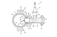
- FIG. 1 is a cross-sectional view showing the overall structure of a water pipe 11 and a water faucet 14 according to the present invention.
- the gate valve 15 is attached and fixed to the peripheral wall of the water pipe 11 via a saddle 30, and the perforator 43 (shown in FIG. 7) moves forward and backward in the water flow tube 16 of the gate valve 15.
- the drill body 44 (shown in FIG. 7) is used to perforate each peripheral wall of the existing pipe 12 constituting the water pipe 11 and the rehabilitating pipe 13 built in the water pipe 11, and the gate valve 15 is connected to the perforated water distribution port.
- a faucet 14 is configured.
- FIG. 2 is an explanatory view showing the overall structure of the water faucet 14 having the gate valve 15.
- FIG. 3 is an explanatory view showing a cross-sectional structure of the water faucet 14 having the gate valve 15.
- the water faucet 14 is provided in the middle of the water pipe 16 to open and stop water in the water pipe 16 constituting a part of the water pipe and the water pipe.
- the gate valve 15 is interposed.
- the gate valve 15 includes a valve body 22 that displaces between a closed position where the flow channel is blocked in the water pipe 16 and an open position where the flow pipe 16 is opened, and the displacement of the valve body 22.
- the valve operating shaft 20 has an upper end protruding from the valve box 21 and a valve operating member (not shown) can be attached to the protruding upper end.
- the gate valve 15 employs, for example, a soft seal valve.
- the soft seal valve is a valve with a rubber sealing material attached to the valve body 22 to improve the water stop performance compared to the normal gate valve 15.
- the water faucet 14 has a soft seal valve gate valve 15.
- the water faucet 14 forming method of the present invention can be applied to a water faucet 14 having a normal gate valve 15. it can.
- tube 16 has a pair of flange at the both ends.
- the first flange 17 is formed at one end of the water pipe 16 and the second flange 18 is formed at the other end.
- the first flange 17 is joined to a saddle flange 35 (shown in FIG. 4) on the saddle 30 side so that the water-flow cylinder 16 and the saddle 30 are communicated with each other.
- the second flange 18 is a flange for attaching the drilling machine 43 and the water faucet attaching jig 10 when the water faucet 14 is formed. After the water faucet 14 is attached, another branch pipe 42 is continuously connected. It is a flange to do.
- the second flange 18 is provided with a cylindrical flange 36b protruding outward on the joint surface with the flange of another pipe.
- the sealing performance is maintained by interposing this cylindrical flange 36b and rubber packing 37b (shown in FIG. 1).
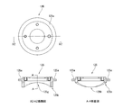
- FIG. 4A is a side view showing the structure of the saddle 30
- FIG. 4B is a plan view showing the structure of the saddle 30
- FIG. 4C is a cross-sectional view showing the structure of the saddle 30.
- the saddle 30 has a rectangular shape when viewed from the side, and its cross section is formed in a substantially arc shape.
- the saddle 30 is used for connecting a water faucet.
- the semi-annular saddle 30 is integrated with a semi-annular band 38 attached in close contact with the peripheral surface of the water pipe 11, and has an annular saddle configuration.
- a body is formed, and the outer periphery of the water pipe 11 where the water faucet 14 is formed is surrounded.
- the mounting cylinder 32 of the saddle 30 and the protruding cylinder 55 provided on the water faucet 14 are connected to each other through a joint between the saddle flange 35 and the first flange 17 and communicated in this way.
- the pipe 11 and the water faucet 14 are communicated with each other via the saddle 30.
- the inflow opening 24 of the gate valve 15 is closed by a partition wall 25 formed along the outer peripheral wall surface curvature of the water pipe 11. That is, a protruding cylinder 55 is extended from the flowing water cylinder 16 of the gate valve 15, and the protruding cylinder 55 is fitted to a mounting cylinder 32 of the saddle 30 described later, as shown in FIGS. 2 and 3.
- the projecting cylinder 55 serves as a water conduit for branching water flowing through the water pipe 11 to the water faucet 14.
- the protruding cylinder 55 is formed with a tapered inner diameter surface 27 whose inner diameter is larger than the inner diameter of the flowing water cylinder 16. As shown in FIG. 3, the tapered inner diameter surface 27 is formed on the first flange 17 side. Thereby, the turbulent flow by the internal-diameter difference of the protrusion cylinder 55 and the water flow pipe
- the inner surface of the projecting cylinder 55 is tapered, but the water faucet 14 forming method of the present invention can also be applied to the projecting cylinder 55 having no inner taper shape.
- a partition wall 25 is formed at the end of the protruding cylinder 55 on the saddle 30 side. As shown in FIG. 3, the partition wall 25 is formed by a curve of curvature that closes the water outlet 62 along the outer peripheral wall surface curvature of the water pipe 11. Therefore, as shown in FIG. 3, the end of the protruding cylinder 55 can come into contact with the peripheral edge of the water diversion port 62 along the surface of the water pipe 11.
- the inflow opening 24 is formed by perforating the partition wall 25 with the perforator 43.
- the inflow opening 24 is perforated simultaneously with the peripheral wall of the water pipe 11 to form a water diversion port 62.
- the water pipe 11 and the gate valve 15 are integrally connected to each other through the water diversion port 62.
- a sealing function is achieved by interposing the rubber packing 23 and the metal sleeve 40 in the water distribution port 62.
- a center drill guide small hole 26 corresponding to the center position of the water faucet 14 of the water pipe 11 is formed in the center of the partition wall 25.
- a center drill guide small hole 26 is formed at the center position of a partition wall 25 having a curve with the same curvature as the outer peripheral wall of the water pipe 11, and the center drill guide small hole 26 is a gate.
- the valve 15 side is formed in a taper shape, and the saddle 30 side is formed in a straight shape.
- the center drill guide small hole 26 has a smaller diameter than the diameter of the center drill 45 main body. The small hole 26 serves as a guide when drilling with the center drill 45.
- the drilling machine 43 includes a core drill 46 and a center drill 45 on the distal end side of the proximal drill shaft.
- the core drill 46 is formed in a cylindrical shape with an open end in order to drill the water pipe 11 with a large diameter, and a drilling blade 46 a is attached to the tip portion.
- the center drill 45 pierces the center drill guide small hole 26 in advance of the core drill 46, is projected from the central axis of the tip of the core drill 46, is formed in a long and thin rod shape with a sharp tip, and its tip Protrudes forward from the drilling blade 46a at the periphery of the core drill 46.
- the center drill guide small hole 26 is a through hole, but it may be a hole that is not a through hole.
- the shape of the hole can also be formed in a triangular cross section, for example.
- the shape of the through hole and the hole is not particularly limited.
- center drill guide small hole 26 drilled at the center position of the partition wall 25 by the center drill 45 can be used for water pressure inspection of the gate valve 15 used for the water faucet. That is, the valve body 22 is closed, water is charged from a small hole, and a water pressure is applied to confirm the presence or absence of water leakage from the gate valve 15.
- the small hole 26 serves as a guide for the center drill 45, and the center drill 45 can accurately drill at the center position of the partition wall 25. it can. That is, by providing the center drill guide small hole 26, the drill main body 44 of the drilling machine 43 does not shake, and the partition wall 25 can be accurately drilled at the center position of the water faucet 14, and the existing pipe 12
- the rehabilitation pipe 13 can also be accurately drilled to form an accurate water outlet 62 on the peripheral surface of the water pipe 11. Since the holes can be accurately perforated in this way, the occurrence of rubbing and scratches on the water outlet 62 is eliminated, and the possibility of water leakage from the damaged portion of the water outlet can be eliminated.
- a core drill guide hole 64 having the same diameter as the core drill 46 is provided in the partition wall 25 in advance, and the core drill 46 is positioned by the guide hole, so that the existing pipe 12 and the rehabilitated pipe 13 are simultaneously drilled.
- the water port 62 is accurately formed.
- FIG. 9 is an explanatory view of a gate valve in which a core drill guide hole 64 is provided in the partition wall 25 in advance. That is, as shown in FIG. 9, in this embodiment, a core drill guide hole 64 is directly provided in the partition wall 25 instead of the center drill guide small hole 26 of the first embodiment.
- a core drill guide hole 64 having substantially the same diameter as the core drill 46 is formed in the partition wall 25 before drilling by the drilling machine 43. That is, in the state where the center of the partition wall 25 having the same curvature as that of the existing pipe 12 is aligned with the center position of the core drill 46, the positioning core drill guide hole 64 having the same diameter as the core drill 46 is provided. Provided.
- the structure other than the core drill guide hole 64 is the same as that of the first embodiment.
- the core drill 46 When drilling the partition wall 25 with the drilling machine 43, the core drill 46 has the same diameter as the hole of the partition wall 25, so the core drill 46 enters along the core drill guide hole 64 and the existing pipe 12 and the renovated pipe. 13 can be drilled with the same diameter as the core drill guide hole 64, and thus the existing pipe 12 and the rehabilitated pipe 13 can be drilled with high accuracy.
- the steps other than the punching process are the same as those in the first embodiment.
- the partition body 25 and the saddle correspond to the center position of the water faucet 14 without causing slight vibration in the drill body 44.
- a water outlet can be drilled in each of the main body 31 and the water pipe 11 accurately and simultaneously.
- a protruding collar portion 28 having a reduced outer diameter of the protruding cylinder 55 is formed at the end of the protruding cylinder 55 (on the saddle 30 side) of the gate valve 15.
- the protruding flange 28 is formed by the mounting step 29a, and the outer diameter of the partition wall 25 that closes the opening end of the protruding cylinder 55 is reduced. Therefore, when the mounting cylinder 32 and the protruding cylinder 55 are fitted and communicated, the mounting step 29a having a reduced diameter of the partition wall 25 and the mounting step 29b at the base of the mounting cylinder 32 protruding from the saddle 30 are provided. By making contact with the sealing member 47 interposed therebetween, a complete sealing function between the mounting cylinder 32 and the protruding cylinder 55 can be achieved.
- a mounting step 29 b is provided around the base end side of the mounting cylinder 32 of the saddle 30 on the saddle 30 side.
- an annular sealing mechanism is formed by combining the mounting step 29a on the gate valve 15 side and the mounting step 29b on the saddle 30 and interposing the seal member 47 therebetween. Is done.
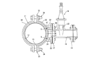
- FIG. 5 is an explanatory view illustrating a state in which the saddle 30 is attached to the water pipe 11.
- a band 38 is attached to the peripheral wall of the water pipe 11
- a saddle 30 is attached integrally to the band 38 and fixed by bolts and nuts 34 via flanges.
- the saddle 30 and the band 38 are integrally attached so as to surround the outer periphery of the water pipe 11.
- the gate valve 15 is attached to the saddle 30 by joining the saddle flange 35 on the side of the saddle 30 and the first flange 17 on the side of the water faucet 14 and fixing them with the mounting bracket 68.
- the protruding cylinder 55 of the gate valve 15 protrudes from the first flange 17 to the saddle 30 side.
- the protruding cylinder 55 is fitted into the mounting cylinder 32 of the saddle 30.
- the partition wall 25 at the end of the projecting cylinder 55 has the same curvature as the existing pipe 12 and the like, the projecting cylinder 55 is fitted in the mounting cylinder 32 of the saddle 30.
- the partition wall 25 abuts along the outer peripheral portion of the water pipe 11.
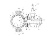
- FIG. 7 is an explanatory view for explaining a state in which the perforator 43 is attached to the gate valve 15.
- a drilling machine 43 is attached to one side of the water pipe 16 of the gate valve 15, and the drilling machine 43 includes a core drill 46 and a center drill 45 on the distal end side of the proximal drill shaft.
- the gate valve 15 is opened, and the center drill 45 and the core drill 46 are made to enter from the one side in the water pipe 16. Then, the drill body 44 is advanced until the tip of the center drill 45 comes into contact with the center drill guide small hole 26.
- the punching machine 43 is driven to punch the existing pipe 12 and the rehabilitated pipe 13. That is, as shown in FIG. 7, the center drill 45 is inserted into the center drill guide small hole 26.
- the small hole 26 functions as a progress guide for the core drill 46, and if the core drill 46 advances as it is, a water diversion port 62 is formed in the peripheral wall of the water pipe 11 together with the partition wall 25.
- the drilling machine 43 is advanced while assuming the drilling center with the center drill guide small hole 26, and the regenerated pipe 13 and the existing pipe 12 are simultaneously drilled together with the partition wall 25 by the core drill 46.
- the drill of the drilling machine 43 is removed from the gate, and the valve body 22 of the gate valve 15 is closed. Then, the punching machine 43 is removed from the water faucet 14 to complete the punching process.
- the subsequent diameter expansion process will be described in detail in Example 3.
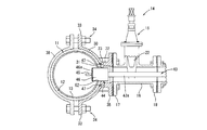
- FIG. 11 is a cross-sectional view illustrating the entire structure of the water pipe 11 and the water tap 14 according to the second embodiment.
- a partition wall is provided in the center of the saddle 30, and a gate valve 15 is attached to the peripheral wall of the water pipe 11 via the saddle 30.
- the drill body 44 (shown in FIG. 18) of the drilling machine 43 (shown in FIG. 18) is inserted into the water pipe 16 of the gate valve 15 and the existing pipe 12 and rehabilitated pipe 13 together with the partition wall of the saddle 30. Peripheral walls are drilled simultaneously. In this way, a water faucet structure in which the water pipe 11 and the water faucet 14 having the gate valve 15 are integrally connected is completed.
- FIG. 12 is an explanatory view showing the entire structure of the water faucet 14 having the gate valve 15.
- FIG. 13 is an explanatory view showing a cross-sectional structure of the water faucet 14 having the gate valve 15, as shown in FIGS. 12 and 13, a pair of water pipes 16 of the gate valve 15 in this embodiment are provided at both ends.
- a flange is provided.
- a first flange 17 is formed at one end of the water pipe 16 of the gate valve 15, and a second flange 18 is formed at the other end.
- the first flange 17 can be joined to the saddle flange 35 on the saddle 30 side.
- the second flange 18 can attach the drilling machine 43 and the water faucet attaching jig 10 when the water faucet 14 is formed, and can be connected to another branch pipe 42 after the water faucet 14 is formed. .
- FIG. 14A is a side view showing the structure of the saddle 30,
- FIG. 14B is a plan view showing the structure of the saddle 30, and
- FIG. 14C shows the tapered inner diameter surface 27.
- FIG. 14D is a cross-sectional view showing the structure of the saddle 30 that does not have a tapered surface.
- the semi-annular saddle body 31 constituting the saddle 30 according to the present invention is formed along the outer peripheral wall surface curvature of the existing pipe 12 and the rehabilitated pipe 13, and a mounting cylinder 32 projects from the center portion.
- the base portion 32 is closed by a semi-annular saddle body 31 along the outer peripheral wall surface curvature of the water pipe 11, and the bottomed portion of the mounting cylinder 32 is used as a partition wall.
- a center drill guide small hole 26 (shown in FIG. 14C) is drilled in the partition wall corresponding to the position to be the center of the water faucet 14.
- center drill guide small hole 26 In the center drill guide small hole 26, the gate valve 15 side is formed in a taper shape, and the rehabilitation pipe 13 side is formed in a straight line.
- the center drill guide small hole 26 has a smaller diameter than the diameter of the center drill 45 main body. The small hole 26 serves as a guide when drilling with the center drill 45. This reason is as described in the previous embodiment.
- the water pipe 11 is simultaneously drilled together with the partition wall of the saddle body 31 at the center position of the water tap 14 to form a water outlet 62.
- the inner diameter of the mounting cylinder 32 on the side of the saddle flange 35 is a tapered inner diameter that is larger than the inner diameter of the water flow cylinder 16 of the main body of the gate valve 15.
- a surface 27 is formed.
- the saddle flange 35 side of the mounting cylinder 32 is tapered.
- the tapered inner diameter surface 27 shown in FIG. 14 (d) is not formed. The mounting cylinder 32 may be applied.
- a seal ring arrangement space S is formed on the saddle 30 side. Then, as shown in FIG. 11, the seal member 47 is interposed in the seal ring disposition space S, thereby maintaining a close seal ring function between the outer peripheral surface of the water pipe 11 and the inner peripheral surface of the saddle 30.
- FIG. 19 is an explanatory view showing another embodiment in which a core drill guide hole 64 having approximately the same diameter as the core drill 46 is provided in advance in the saddle body 31 before drilling by the drilling machine 43. That is, as shown in FIG. 19, in place of the center drill guide small hole 26 in the second embodiment, a core drill guide hole 64 is directly provided in the saddle body 31 in advance in the present embodiment. .
- the structure other than the core drill guide hole 64 is the same as that of the second embodiment.
- the water faucet 14 forming method mainly includes a saddle mounting process, a gate valve mounting process, a drilling process, and a diameter expansion process.
- FIG. 15 is an explanatory diagram for explaining a state in which the saddle 30 is attached to the water pipe 11.
- FIG. 16 is an explanatory diagram for explaining a state in which the gate valve 15 is combined with the saddle 30.
- the saddle mounting process and the gate valve mounting process are substantially the same as in the first embodiment.
- FIG. 17 is an explanatory diagram for explaining a state in which the perforator 43 is attached to the gate valve 15. Further, a drilling machine 43 provided with a core drill 46 and a center drill 45 is attached to one side of the water pipe 16 on the distal end side of the proximal drill shaft.
- the perforation is the same as the step of perforating the water diverting port with the core drill 46 of the water pipe 11 together with the partition wall 25 provided on the protruding cylinder 55 of the gate valve 15.
- the partition wall formed in the saddle body 31 is used as the water pipe. The only difference is that it drills with 11 outer peripheral walls.
- the existing pipe 12 and the rehabilitated pipe 13 can be simultaneously drilled together with the saddle body 31 to form the water diverting port 62.
- FIG. 20 is a cross-sectional view showing the configuration of the water faucet mounting jig and the state in which the water faucet mounting jig is connected to the gate valve.
- the water faucet mounting jig 10 is provided with a handle operating mechanism in which various handles (a pulling handle 117 and a diameter expanding handle 118) are concentrated on the upper part.
- An upper flange 2 is provided at the lower portion of the handle operating mechanism, and a lower flange 3 is disposed below the upper flange 2 at a predetermined interval in the longitudinal direction of the water faucet mounting jig 10.
- the lower flange 3 is integrally connected to the second flange 18 at the upper end of the gate valve 15 via a mounting plate 115 and a positioning flange 114.
- a main shaft 111 is vertically suspended from the center of the water faucet mounting jig 10, and an upper flange 2 is fixed to the upper portion of the main shaft 111, while the gate valve 15 has a lower flange as described above.
- 3 is connected and fixed, and two trapezoidal screws 112 and 112 are constructed in a rectangular frame shape as an elevating mechanism for moving up and down the main shaft 111 and are installed on the upper and lower flanges 2 and 3.
- the trapezoidal screw is screwed to the fixed lower flange 3 through the screw hole 3a.
- the projecting upper end of the trapezoidal screw 112 inserted through the upper flange 2 is rotatable, and the upper flange 2 and the spindle 111 are moved up and down together with the trapezoidal screw 112 by rotating the rotating portion 112a at the upper end of the trapezoidal screw 112 with a dedicated tool. Operate.
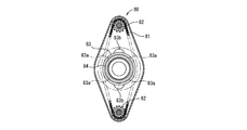
- interlocking mechanism 80 indicates an interlocking mechanism
- 82 and 82 indicate sprockets
- 81 indicates a chain
- 83 indicates a chain tension adjusting device
- 83a indicates a fixing screw.
- the main shaft 111 is inserted into the sleeve push-out pipe 54, the eccentric movable shaft 52 inserted through the sleeve push-out pipe 54, and the sectional movable space between the eccentric movable shaft 52 and the sleeve push-out pipe 54.
- An eccentric movable bearing 53 for stably supporting the sleeve push-out pipe 54 is used.
- An eccentric diameter expanding head 57 that rotates simultaneously with the rotation of the eccentric movable shaft 52 is connected to the lower end of the eccentric movable shaft inserted into the sleeve push-out pipe 54, and a rubber packing 23 is disposed on the peripheral surface of the diameter expanding head 57.
- a metal sleeve 40 is loosely fitted between the inner peripheral surface of the upper portion of the rubber packing 23 and the peripheral surface of the diameter expanding head 57.
- the lower portion of the sleeve push-out pipe 54 is formed in a cylindrical shape that is thicker than the upper portion of the sleeve push-out pipe 54, and the lower end contact end 54 a is in contact with the flange 40 a of the head of the metal sleeve 40 fitted to the rubber packing 23. It is configured.
- the diameter expansion head 57 is provided with a diameter expansion roller 51 obliquely upward.
- the diameter-expanding roller 51 is formed into a drum shape by a plurality of roller pieces cut and divided into a plurality of ring-cut states, and each roller piece is configured to be independently rotatable.
- a guide member 70 for smoothly and accurately entering the water diverting port 62 is connected to the lower end of the diameter expanding head 57 (that is, the tip inserted into the water diverting port 62 drilled in the water pipe 11). It is installed.
- the eccentric movable shaft 52 rotates eccentrically from the center of the main shaft 111, so that the diameter expansion roller 51 obliquely provided on the diameter expansion head 57 is outside the outer diameter of the main shaft 111, that is, the outer diameter of the sleeve extrusion pipe 54. It will be free to appear and disappear. That is, if the diameter-expanding roller 51 is immersed in the cross-sectional space between the eccentric movable shaft 52 and the sleeve push-out pipe 54, it can be inserted through the water diverting port 62 in that state, and then advances to the tip of the water diverting port.
- the diameter-expanding roller 51 is rotated so that it protrudes outward from the cross-sectional space between the eccentric movable shaft 52 and the sleeve push-out pipe 54. In this way, the diameter expansion roller 51 is displaced to a position where the rubber packing 23 and the metal sleeve 40 positioned around the water diversion opening can be caulked.
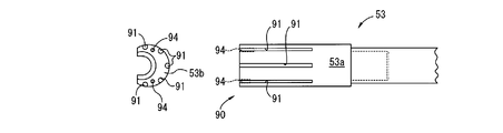
- seizure prevention is performed to prevent seizure due to friction between the outer peripheral surface of the eccentric movable bearing 53 and the inner peripheral surface of the metal sleeve 40.
- a member 90 is provided. Details of the seizure prevention member 90 will be described later.
- Handles for operating the sleeve push-out pipe 54, the eccentric movable shaft 52 (diameter expansion head 57), the eccentric movable bearing 53, and the like constituting the main shaft 111 are provided at the upper part of the water faucet mounting jig 10, respectively.
- Reference numeral 117 denotes a lifting handle
- reference numeral 118 denotes a diameter expansion handle.
- the lifting handle 117 rotates the eccentric movable shaft 52 eccentrically, and causes the diameter expansion roller 51 obliquely provided on the diameter expansion head 57 to appear and appear on the inner and outer sides of the outer diameter of the main shaft 111. Further, the lifting handle 117 performs the lifting operation of the diameter expansion head 57 that has advanced to the outside of the outer diameter of the main shaft 111, thereby opening the tip opening portion of the metal sleeve 40 that protrudes into the water pipe 11. It is deformed by a predetermined pressure of the diameter-enlargement roller 51 obliquely provided on the surface.
- the diameter expansion handle 118 turns the main shaft 111 while abutting the diameter expansion roller 51 obliquely provided on the diameter expansion head 57 to the tip opening of the metal sleeve 40, and turns the opening tip of the metal sleeve 40 outward. It is for bending in the state.
- reference numeral 19a denotes a lever for enabling the eccentric movable shaft 52 to rotate alone or for allowing the eccentric movable shaft 52 and the eccentric movable bearing 53 to rotate together.
- the water faucet attachment jig 10 is attached to the gate valve 15 via the positioning flange 114, the attachment plate 115 at the lower end of the water faucet attachment jig 10, the second flange 18 of the gate valve 15, and the like.
- the rubber packing housing space G for fastening the flange portion 23a of the rubber packing 23 is formed in the mounting cylinder 32 (see FIG. 23), and the flange portion 23a is formed long. There is no possibility that the rubber packing 23 enters the water pipe 11 from the water outlet 62. Further, the flange portion 23 a of the rubber packing 23 can withstand the strong insertion pressure of the metal sleeve 40 by a split ring 23 b provided on the flange portion 23 a of the rubber packing 23 described later.
- the main shaft 111 is lowered and the sleeve push-out pipe 54 moves the metal sleeve.
- the tip opening 40 b of the metal sleeve 40 passes through the inner periphery of the rubber packing 23 and penetrates into the water pipe 11.
- the diameter expanding head 57 arranged at the lower end of the main shaft 111 is in a state of projecting further inward than the tip opening 40b of the metal sleeve 40 projecting from the water diversion port 62 into the water pipe 11.
- the diameter expansion head 57 is in a state where the diameter expansion roller 51 obliquely provided on the diameter expansion head 57 is immersed inside the outer diameter of the main shaft 111.
- the rubber packing accommodation space G is a space for preserving the compressive force of the rubber packing 23 when the flange portion 23a of the rubber packing 23 is compressed.
- the eccentric movable shaft 52 is rotated by approximately 180 degrees, and as shown in FIG. 34, the diameter expanding roller 51 obliquely provided on the diameter expanding head 57 is placed outside the outer diameter of the main shaft 111. Advance. Then, the pulling handle 117 (see FIG. 20) is operated to bring the diameter expansion roller 51 into contact with the tip opening 40b of the metal sleeve 40 with a predetermined pressure.
- the eccentric movable shaft 52 and the eccentric movable bearing 53 are locked so as to rotate integrally by operating the integral lock mechanism, and the eccentric handle 118 (see FIG. 20) is rotated to rotate the eccentric movable shaft 52 and the eccentric movable shaft.
- the bearing 53 is rotated integrally.
- the lifting handle 117 (see FIG. 20) is operated to operate in the opposite direction to the above, and the diameter expansion roller 51 is buried inside the outer diameter of the main shaft 111 (see FIG. 33). Then, the main shaft 111 is advanced to a position where the valve element 22 of the gate valve 15 can block the water diversion channel 63 by the lifting mechanism, and the flow of water from the water pipe 11 to the water diversion channel 63 is blocked.
- the water faucet attachment jig 10 attached to the second flange 18 of the gate valve 15 is removed together with the positioning flange 114, and the operation of forming the water faucet 14 is completed. That is, as shown in FIG. 26, a water faucet in which the tip opening 40b of the metal sleeve 40 is expanded in diameter so that the metal sleeve 40 is integrally crimped to the water distribution port 62 of the water pipe 11 together with the rubber packing 23. 14 is formed. Then, a water branch pipe (not shown) is connected to the second flange 18 of the gate valve 15, and then the gate valve 15 is opened to divert water from the water pipe 11 to the water diversion channel 63.
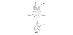
- the diameter-enlarging roller 51 according to the present invention is cut and divided into two ring-shaped roller pieces 51a and 51b at substantially the center and integrally formed into a drum shape. 51a and 51b are rotatable independently of each other. In FIG. 28, a slight linear step is provided at the contact end K of each of the roller pieces 51a and 51b. In FIG. 29, the contact end K of each roller piece 51a, 51b is formed in an R shape.
- the enlarged diameter surface R can be divided
- the diameter increasing roller 51 is cut and divided into four ring-shaped roller pieces 51a, 51b, 51c, 51d. And the roller pieces 51a, 51b, 51c, 51d are configured to be rotatable independently of each other, thereby preventing an increase in the diameter-enhancing prevention force of the diameter-enlarging roller 51. It gets even higher.
- the contact end K of each roller piece 51a, 51b, 51c, 51d is formed in R shape.
- the diameter of the tip opening 40b of the metal sleeve 40 can be increased with a light rotational force. Further, the buckling when the diameter of the tip opening 40b of the metal sleeve 40 is expanded is eliminated, and the accuracy of the diameter expansion can be improved.
- FIG. 31 is a cross-sectional view showing the structure of the metal sleeve 40 of the present invention.
- FIG. 32 is a cross-sectional view showing the structure of the rubber packing 23 fitted with the split ring 23b of the present invention.
- the metal sleeve 40 has an outer flange-shaped flange 40a formed at the upper end, and this flange 40a abuts on the contact end 54a of the sleeve push-out pipe 54, and the sleeve push-out pipe 54 is moved up and down.
- the tip opening 40b of the metal sleeve 40 is projected into the water pipe 11. Further, the flange 40 a comes into contact with the upper end of the rubber packing 23 and is locked to the metal sleeve 40.
- the metal sleeve 40 is formed in a cylindrical body with the outer peripheral surface 40c as a mounting allowance with the inner peripheral surface of the rubber packing 23.
- the metal sleeve 40 is formed in a cylindrical body having an outer flange-like flange portion 40a projecting from the upper end, and the tip opening end surface 40b is formed in a wave-like uneven shape. That is, as shown in FIG. 42, the left and right half end surfaces 40g of the annular tip opening end surface 40b are formed in a semicircular arc-shaped recess substantially along the inner peripheral portion of the water pipe 11, while the annular tip opening end surface The upper and lower half end face portions 40 h of 40 b are formed in a semicircular arc-shaped convex portion that is substantially along the inner peripheral longitudinal direction of the water pipe 11.
- the rubber packing 23 is composed of an upper half flange portion 23a and a lower half mounting portion 23f.
- the upper half inner peripheral surface is a loose fitting allowance 23d with the metal sleeve 40, and
- the half inner peripheral surface is formed into a cylindrical body having a fitting allowance 23 e with the lower end peripheral surface of the main shaft 111.
- the loose allowance 23d and the fit allowance 23e have substantially the same thickness, and the inner diameter of the allowance allowance 23d and the fit allowance 23e is larger than the fit allowance 40e because the metal sleeve 40 is loosely fitted.
- a step portion 23c is formed.
- a flange portion 23a which is a narrowed step portion, is formed in the vicinity of the step portion 23c inside the rubber packing 23 and at the outer periphery of the lower end.
- the flange portion 23a has an annular notch (D portion) divided ring. 23b can be fitted.
- the split ring 23 b is configured to perform an inhibiting function so that the metal sleeve 40 does not advance from a predetermined position of the rubber packing 23.
- the split ring 23b By attaching the split ring 23b to the rubber packing 23, the split ring 23b functions to press the rubber packing 23 from the outer periphery, so that the flange portion 23a of the rubber packing 23 can withstand the strong insertion pressure of the metal sleeve 40. become. Moreover, since the outer diameter of the flange part 23a of the rubber packing 23 can be made small by using the split ring 23b, the gate valve 15 can be made smaller.
- the lower end opening end surface of the rubber packing 23 is formed in a waved shape so as to correspond to the metal sleeve 40 of the other embodiment. That is, as shown in FIG. 41, the left and right half end surface portions are formed in a half end surface-like concave portion 23g substantially along the inner peripheral surface of the water pipe 11, while the upper and lower half end surface portions are substantially along the inner peripheral longitudinal direction of the water pipe 11. It forms in such a semicircular arc-shaped convex part 23h.
- FIG. 35 is a view showing a state in which the guide member 70 is attached to the lower end of the diameter expanding head 57.
- FIG. 36 is an exploded view illustrating the configuration of the guide member 70.
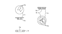
- a guide member 70 such as a base 71, an elastic guide member 72, and a taper guide member 73 is integrally attached to the lower end of the diameter expansion head 57 by bolts 74, and these members are the diameter expansion head 57. It functions so that the rubber packing 23 attached to the can be accurately entered into the water diversion port 62 formed in the water pipe 11.
- the base 71 is for stably attaching the elastic guide member 72 to the tip of the diameter expanding head 57, and a fitting portion 71a of the elastic guide member 72 is provided at the center.
- the elastic guide member 72 is formed in a donut shape using an elastic member that shrinks in response to pressure, and is attached to the base 71 by fitting a central hole 72 a to the fitting portion 71 a of the base 71.
- the taper guide member 73 is formed in an inverted trapezoidal cylindrical shape having a short side at the short side and a long side at the top side, and is attached to the lower surface of the fitting portion 71 a of the base 71.
- three attachment holes 73a provided through the taper guide member 73 and three attachment holes 71b provided on the lower surface of the fitting portion 71a of the base 71 are connected by bolts.
- the elastic guide member 72 is a member for guiding the rubber packing 23 attached to the diameter expansion head 57 to the water diversion port 62 drilled in the water pipe 11, and has a radius larger than the inner diameter of the metal sleeve 40.
- the taper guide member 73 has an inverted trapezoidal shape with a short lower side, is made of a hard member such as metal, and even when the central axis of the water diversion port 62 and the axis of the main shaft 111 are deviated within a tolerance range. It functions so that the diameter expansion head 57 can be smoothly inserted into the water diversion port 62.
- the outer diameter of the taper guide member 73 is smaller than the inner diameter of the metal sleeve 40.
- the elastic guide member 72 is configured to reduce the diameter in accordance with the pressure, the tip of the rubber packing 23 can be accurately guided to the water distribution port 62.
- the elastic guide member 72 larger than the inner diameter of the metal sleeve 40 can be pulled out from the water diverting port 62 by reducing the diameter in accordance with the pressure. Yes.
- the guide member 70 having the above-described configuration on the lower surface of the diameter expansion head, even when the central axis of the water diverting port 62 and the central axis of the main shaft 111 are swung within a tolerance range, the lower end of the main shaft 111 is Since it can be inserted into the water distribution port 62, the elastic guide member 72 can guide the tip of the rubber packing 23 to the water distribution port 62 with high accuracy. With this configuration, it is possible to automatically correct the central axis of the water diverting port 62 and the central axis of the main shaft 111 to coincide with each other.
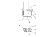
- a plurality of (six in the figure) grooves 91 are provided on the outer peripheral surface 53a of the eccentric movable bearing 53, and a metallic cylindrical roller 92 is rotatably accommodated.
- the outer peripheral surface of the roller 92 partially protrudes from the outer peripheral surface 53 a of the eccentric movable bearing 53 so as to be able to contact the inner peripheral surface of the metal sleeve 40.
- a cover 93 is continuously provided on the bottom bottom surface 53 b of the eccentric movable bearing 53 so that the roller 92 does not fall out of the groove 91.
- 94 is a cover mounting hole provided in the bottom bottom surface 53 b of the eccentric movable bearing 53
- 95 is a mounting hole provided in the cover 93
- 99 is a fixing bolt inserted into each mounting hole 94, 95.
- the outer peripheral surface 53a of the eccentric movable bearing 53 that rotates the main shaft 111 and contacts the inner peripheral surface of the metal sleeve 40 is curved along the shape of the outer peripheral surface 53a.
- the anti-seizure member 90 is configured by attaching a metal plate 97 having excellent properties.
- FIG. 40 is a diagram illustrating a modification of the lifting mechanism.
- FIG. 40 is a diagram illustrating a modification of the lifting mechanism. In the following modifications, only points different from the above-described embodiment will be described, and the same portions will be denoted by the same reference numerals and description thereof will be omitted.
- the elevating mechanism according to the modification includes a lower part in which one of the left and right trapezoidal screws 112 attached to the upper flange 2 in a frame shape is used as a guide rod 113 and one of the trapezoidal screws 112 is fixed to the gate valve.
- the upper flange 2 is moved up and down together with the trapezoidal screw 112 by screwing into the flange 3 and rotating the screw thus screwed.
- the main shaft 111 attached to the upper flange 2 is also configured to move up and down.
- the guide rod 113 guides the main shaft 111 that moves up and down together with the upper flange 2 by being inserted into the insertion hole 3b provided in the lower flange 3 so that it can be moved up and down accurately without shaking. Further, not only one guide rod 113 but also a plurality of guide rods 113 can be provided in parallel with the trapezoidal screw 112, and the accuracy of raising and lowering (especially lowering) the main shaft 111 can be further improved.
- FIGS. 41 and 42 show another embodiment of the water faucet mounting jig 10. That is, as shown in FIGS. 41 and 42, when the lower end opening edge of the rubber packing 23 and the lower end opening edge of the metal sleeve 40 are waved unevenly along the inner peripheral surface of the water pipe, these deformed opening edges The caulking work must be carried out along the circumference of the diversion outlet in the water pipe. For this purpose, it is necessary to configure the jig structure so as to give a certain change to the elevation and rotation of the water faucet attachment jig 10.
- the interlocking mechanism 80 is configured to move up and down the main shaft 111 according to the corrugated shape of the rubber packing 23 and the metal sleeve 40.
- the interlock mechanism 80 includes a fixed side member and a movable side member.
- the fixed side member includes a fixed shaft 121, a chain base 122, a cam base 123, and a tension ring 124, and the movable member is a cylinder.
- a cam 125 and a connecting member 126 to the main shaft 111 are included.
- 133 indicates an upper cover
- 134 indicates a lower cover.
- the fixed shaft 121 is formed in a cylindrical shape and is integrally fixed to the jig body.
- the chain base 122 has a rhombus shape in plan view and is fixed on the fixed shaft 121, and a cylindrical body 130 projects upward from the center.
- a sprocket 81 and a chain 82 are disposed above the left and right sides of the chain base 122.
- the cam base 123 is formed in a cylindrical shape, and an annular cam groove 127 is formed on the upper surface side of the cylindrical cam base 123 and the roller hole 128 is penetrated in the radial direction. Yes.
- a roller 129 is loosely fitted in the roller hole 128 via a bush 132, and both shaft ends of the roller 129 are connected to the tension ring 124 and a cylindrical body 130 protruding from the center of the chain base 122. It is pivoted between. As shown in FIG. 43, a tension ring 124 is attached to the outer periphery of the cam base 123, and the roller 129 is configured not to be detached from the roller hole 128 by covering the roller hole 128 of the cam base 123 with the tension ring 124. ing.
- the cylindrical cam 125 is formed in a corrugated uneven shape by projecting the cam body 125a in a cylindrical shape on the bottom surface side. That is, as shown in FIG. 46, the left and right half end surface portions are formed in a half end surface concave portion 125g substantially along the inner peripheral surface of the water pipe 11, while the upper and lower half end surface portions are substantially along the inner peripheral longitudinal direction of the water pipe 11. Such a semicircular arc-shaped convex portion 125h is formed.
- the cylindrical cam 125 is slidably fitted into the cam groove 127 of the cam base 123, and the lower end edge of the cylindrical cam 125 is in pressure contact with the roller 129.
- the cylindrical cam 125 is integrally connected to the main shaft 111 via the connecting member 126.
- the main shaft 111 can be moved up and down by rotating the diameter expansion handle 118 when the diameter of the metal sleeve 40 is expanded. That is, when the diameter expansion handle 118 is rotated, the main shaft 111 rotates, and the cylindrical cam 125 connected integrally with the main shaft 111 also rotates. Since the lower end edge of the cylindrical cam 125 formed in the corrugated shape is in contact with the roller 129, the cylindrical cam 125 is moved up and down by the rotation of the roller 129, and the main shaft 111 connected integrally with the cylindrical cam 125 is also moved up and down. . Therefore, as shown in FIG.
- the rubber packing 23 and the metal sleeve 40 which are crimped to the peripheral edge of the water distribution port 62, are processed into a flat shape without a bump along the peripheral wall surface of the water pipe, so that the water flow area in the vicinity of the water distribution port 62 can be reduced as much as possible. It can be widely used, and it is easy to insert a pig or a washing machine when cleaning the inside of the pipe.
- the innermost rehabilitation pipe 13 is a soft and unstable material pipe such as a composite pipe or a plastic pipe. Since the peripheral portion of the water distribution port 62 in the pipe is uniformly wrapped with the rubber packing 23 and the metal sleeve 40, stable water branching can be performed despite the double water pipe, and the construction work of the water tap is also accurate. And it can carry out simply.
Landscapes
- Engineering & Computer Science (AREA)
- General Engineering & Computer Science (AREA)
- Mechanical Engineering (AREA)
- Physics & Mathematics (AREA)
- Fluid Mechanics (AREA)
- Branch Pipes, Bends, And The Like (AREA)
- Drilling And Boring (AREA)
Abstract
Priority Applications (6)
| Application Number | Priority Date | Filing Date | Title |
|---|---|---|---|
| US14/778,307 US9719621B2 (en) | 2013-03-21 | 2014-03-24 | Snap tap forming method and snap tap attaching tool used in the method |
| JP2015506870A JP6211060B2 (ja) | 2013-03-21 | 2014-03-24 | 分水栓形成方法及び同方法に使用する分水栓取付用治具 |
| HK16102323.6A HK1214334B (en) | 2013-03-21 | 2014-03-24 | Snap tap molding method and snap tap attachment tool used in said method |
| EP14770739.2A EP2977660B1 (fr) | 2013-03-21 | 2014-03-24 | Procédé de moulage de robinet à enclenchement et outil de fixation de robinet à enclenchement utilisé dans ce procédé |
| KR1020157025529A KR102101371B1 (ko) | 2013-03-21 | 2014-03-24 | 분수전 형성 방법 및 상기 방법에 사용하는 분수전 설치용 공구 |
| CN201480016385.9A CN105190145B (zh) | 2013-03-21 | 2014-03-24 | 分水栓形成方法及使用同方法的分水栓安装用夹具 |
Applications Claiming Priority (6)
| Application Number | Priority Date | Filing Date | Title |
|---|---|---|---|
| JP2013058820 | 2013-03-21 | ||
| JP2013-058820 | 2013-03-21 | ||
| JP2013-058821 | 2013-03-21 | ||
| JP2013058821 | 2013-03-21 | ||
| JP2013-072200 | 2013-03-29 | ||
| JP2013072200 | 2013-03-29 |
Publications (1)
| Publication Number | Publication Date |
|---|---|
| WO2014148645A1 true WO2014148645A1 (fr) | 2014-09-25 |
Family
ID=51580313
Family Applications (1)
| Application Number | Title | Priority Date | Filing Date |
|---|---|---|---|
| PCT/JP2014/058140 Ceased WO2014148645A1 (fr) | 2013-03-21 | 2014-03-24 | Procédé de moulage de robinet à enclenchement et outil de fixation de robinet à enclenchement utilisé dans ce procédé |
Country Status (6)
| Country | Link |
|---|---|
| US (1) | US9719621B2 (fr) |
| EP (1) | EP2977660B1 (fr) |
| JP (1) | JP6211060B2 (fr) |
| KR (1) | KR102101371B1 (fr) |
| CN (1) | CN105190145B (fr) |
| WO (1) | WO2014148645A1 (fr) |
Cited By (7)
| Publication number | Priority date | Publication date | Assignee | Title |
|---|---|---|---|---|
| JP2016223625A (ja) * | 2015-05-29 | 2016-12-28 | ヨネ株式会社 | 分水栓取付用治具 |
| WO2018163415A1 (fr) * | 2017-03-10 | 2018-09-13 | ヨネ株式会社 | Structure de ramification, procédé de fixation d'une structure de ramification, et outil de fixation d'une structure de ramification |
| JP2018150962A (ja) * | 2017-03-10 | 2018-09-27 | ヨネ株式会社 | 連結管の接続方法 |
| WO2019198149A1 (fr) * | 2018-04-10 | 2019-10-17 | ヨネ株式会社 | Procédé de raccordement pour tuyau d'accouplement |
| JP2020067087A (ja) * | 2018-10-22 | 2020-04-30 | ヨネ株式会社 | 分岐構造の取付け具及び取付け方法 |
| CN114110257A (zh) * | 2021-06-05 | 2022-03-01 | 南昌市政建设集团有限公司 | 一种顶管施工用新型排泥水管道与管道连接件 |
| CN115111429A (zh) * | 2022-06-15 | 2022-09-27 | 武汉船用电力推进装置研究所(中国船舶重工集团公司第七一二研究所) | 一种水冷复杂管路的安装工艺方法 |
Families Citing this family (19)
| Publication number | Priority date | Publication date | Assignee | Title |
|---|---|---|---|---|
| GB201415770D0 (en) * | 2014-09-05 | 2014-10-22 | Taylor Veitch William And Dobbs Kevin | Improved valve apparatus and method of installation |
| CN107350521B (zh) * | 2017-08-29 | 2019-02-26 | 湖北华信建设工程有限公司 | 一种管道开孔器 |
| WO2019056158A1 (fr) * | 2017-09-19 | 2019-03-28 | 东莞好奇智能科技有限公司 | Soupape à bille à raccordement rapide |
| WO2019056154A1 (fr) * | 2017-09-19 | 2019-03-28 | 东莞好奇智能科技有限公司 | Diviseur de fluide |
| CN111448412A (zh) * | 2017-09-19 | 2020-07-24 | 东莞好奇智能科技有限公司 | 流体分流器 |
| WO2019056156A1 (fr) * | 2017-09-19 | 2019-03-28 | 东莞好奇智能科技有限公司 | Dispositif de division de fluide à connexion libre |
| WO2019056157A1 (fr) * | 2017-09-19 | 2019-03-28 | 东莞好奇智能科技有限公司 | Séparateur de gaz |
| CN108506624A (zh) * | 2018-04-12 | 2018-09-07 | 于浩 | 一种化工设备用支流管道 |
| EP3611419B1 (fr) * | 2018-08-14 | 2022-03-16 | Wilhelm Ewe GmbH & Co. KG | Manchon de perforation pour une garniture de percage et procédé pour étancher un tube |
| KR102839891B1 (ko) * | 2018-09-05 | 2025-07-29 | 코스모 코키 가부시키가이샤 | 유체 제어 장치 |
| CN111118859B (zh) * | 2018-10-30 | 2022-04-26 | 无锡小天鹅电器有限公司 | 进水部件安装盒、进水组件和衣物处理装置 |
| CA3118286A1 (fr) | 2018-10-30 | 2020-05-07 | Ina Acquisition Corp. | Raccord pour le raccordement d'un chemisage de tuyau principal a un conduit de derivation |
| US11079055B2 (en) | 2018-10-30 | 2021-08-03 | Ina Acquisition Corp. | Fitting for connecting a main pipe liner to a branch conduit |
| US11391407B2 (en) | 2018-11-30 | 2022-07-19 | Ina Acquisition Corp. | Methods, systems, and apparatus for use in main pipes connected to branch conduit |
| CN111578023B (zh) * | 2019-02-19 | 2022-02-25 | 温玉华 | 输送管线鞍带栓阀的分流装置 |
| CN110005893A (zh) * | 2019-04-22 | 2019-07-12 | 五邑大学 | 一种管道架接机构 |
| CA3155824C (fr) * | 2019-10-11 | 2025-02-04 | Cosmo Koki Co., Ltd. | Dispositif de perçage de conduit |
| CN110701408A (zh) * | 2019-10-12 | 2020-01-17 | 上海友为工程设计有限公司 | 一种用于通水管道不断水开梯的密封方法 |
| CN115461567B (zh) * | 2020-04-28 | 2025-06-06 | 株式会社水道技术开发机构 | 分支管形成装置、阀芯兼用盖、包括阀芯兼用盖的分支管形成装置以及分支管形成方法 |
Citations (7)
| Publication number | Priority date | Publication date | Assignee | Title |
|---|---|---|---|---|
| US4978255A (en) * | 1987-08-19 | 1990-12-18 | Gale John C | Tapping fluid supply pipes |
| JPH09100986A (ja) * | 1995-10-03 | 1997-04-15 | Cosmo Koki Co Ltd | 管体の不断水穴加工方法および装置 |
| JP2625357B2 (ja) * | 1993-09-20 | 1997-07-02 | 株式会社栗本鐵工所 | 分水栓、その取付方法及び装置 |
| JPH09273186A (ja) | 1996-04-05 | 1997-10-21 | Kurimoto Ltd | 分水栓の取付装置 |
| JPH11190457A (ja) | 1997-12-26 | 1999-07-13 | Daiko Seimitsu Kk | ゴムパッキン及び分水栓を水道管に穿孔された分水口に装着するための装置及びシャッター装置並びに分水栓 |
| JP2005036862A (ja) * | 2003-07-18 | 2005-02-10 | Suiken:Kk | 不断水穿孔工法 |
| JP2009535578A (ja) | 2006-04-27 | 2009-10-01 | アイエヌエイ アクイジション コーポレーション | 内張りした導管内の既設の継手部の更生 |
Family Cites Families (15)
| Publication number | Priority date | Publication date | Assignee | Title |
|---|---|---|---|---|
| US3460553A (en) | 1966-12-02 | 1969-08-12 | Mueller Co | Method and connection for establishing service between a plastic main and plastic service pipe with a plastic service t |
| JPS62193713A (ja) * | 1986-02-17 | 1987-08-25 | Yano Giken Kk | 管穿孔方法 |
| FR2678350B1 (fr) | 1991-06-26 | 1993-09-24 | Setha | Collier de prise en charge sur tuyau ciment a ame en tole. |
| ES2136474T3 (es) | 1996-06-12 | 1999-11-16 | Manibs Spezialarmaturen | Procedimiento para la fabricacion de un accesorio para tubo que consiste en un material termicamente soldable. |
| US6640827B1 (en) * | 2001-10-08 | 2003-11-04 | Mcclure Mark A. | Hot tapping tool |
| CN101479518A (zh) * | 2006-04-27 | 2009-07-08 | 伊纳埃克威生公司 | 内衬管道中已有连接器的修复 |
| JP2010116929A (ja) * | 2007-06-21 | 2010-05-27 | Jaehyun Kim | 不断流穿孔用の分岐装置 |
| JP5368009B2 (ja) * | 2008-05-29 | 2013-12-18 | コスモ工機株式会社 | 流体管の穿孔防食装置 |
| WO2010050115A1 (fr) * | 2008-10-27 | 2010-05-06 | 株式会社水研 | Dispositif de dérivation pour perçage d’écoulement ininterrompu |
| US8770897B2 (en) * | 2009-11-04 | 2014-07-08 | Advanced Drainage Systems, Inc. | Coring tool alignment assembly |
| CN201757241U (zh) * | 2010-07-05 | 2011-03-09 | 天津建岩岩土工程有限公司 | 一种用于管道连通的带压作业工具 |
| JP2013071206A (ja) * | 2011-09-28 | 2013-04-22 | Cosmo Koki Co Ltd | 切粉排出装置及びその方法 |
| JP2013252600A (ja) * | 2012-06-08 | 2013-12-19 | Cosmo Koki Co Ltd | 流体管穿孔装置 |
| US8899254B1 (en) * | 2012-06-19 | 2014-12-02 | Yamsmos & Company, Inc. | Valve removal tool and method |
| NL2009187C2 (nl) * | 2012-07-13 | 2014-01-16 | Pipelife Nederland Bv | Opzetinrichting met stromingsindicator. |
-
2014
- 2014-03-24 KR KR1020157025529A patent/KR102101371B1/ko not_active Expired - Fee Related
- 2014-03-24 CN CN201480016385.9A patent/CN105190145B/zh not_active Expired - Fee Related
- 2014-03-24 EP EP14770739.2A patent/EP2977660B1/fr not_active Not-in-force
- 2014-03-24 US US14/778,307 patent/US9719621B2/en not_active Expired - Fee Related
- 2014-03-24 JP JP2015506870A patent/JP6211060B2/ja active Active
- 2014-03-24 WO PCT/JP2014/058140 patent/WO2014148645A1/fr not_active Ceased
Patent Citations (7)
| Publication number | Priority date | Publication date | Assignee | Title |
|---|---|---|---|---|
| US4978255A (en) * | 1987-08-19 | 1990-12-18 | Gale John C | Tapping fluid supply pipes |
| JP2625357B2 (ja) * | 1993-09-20 | 1997-07-02 | 株式会社栗本鐵工所 | 分水栓、その取付方法及び装置 |
| JPH09100986A (ja) * | 1995-10-03 | 1997-04-15 | Cosmo Koki Co Ltd | 管体の不断水穴加工方法および装置 |
| JPH09273186A (ja) | 1996-04-05 | 1997-10-21 | Kurimoto Ltd | 分水栓の取付装置 |
| JPH11190457A (ja) | 1997-12-26 | 1999-07-13 | Daiko Seimitsu Kk | ゴムパッキン及び分水栓を水道管に穿孔された分水口に装着するための装置及びシャッター装置並びに分水栓 |
| JP2005036862A (ja) * | 2003-07-18 | 2005-02-10 | Suiken:Kk | 不断水穿孔工法 |
| JP2009535578A (ja) | 2006-04-27 | 2009-10-01 | アイエヌエイ アクイジション コーポレーション | 内張りした導管内の既設の継手部の更生 |
Cited By (13)
| Publication number | Priority date | Publication date | Assignee | Title |
|---|---|---|---|---|
| EP3276244A4 (fr) * | 2015-05-29 | 2019-01-16 | Yone Corporation | Gabarit pour installer des robinets à pression |
| WO2017168832A1 (fr) * | 2015-05-29 | 2017-10-05 | ヨネ株式会社 | Gabarit pour installer des robinets à pression |
| US10563804B2 (en) | 2015-05-29 | 2020-02-18 | Yone Corporation | Snap tap mounting jig |
| JP2016223625A (ja) * | 2015-05-29 | 2016-12-28 | ヨネ株式会社 | 分水栓取付用治具 |
| JPWO2018163415A1 (ja) * | 2017-03-10 | 2020-01-16 | ヨネ株式会社 | 分岐構造、分岐構造の取付け方法及び分岐構造の取付け具 |
| JP2018150962A (ja) * | 2017-03-10 | 2018-09-27 | ヨネ株式会社 | 連結管の接続方法 |
| WO2018163415A1 (fr) * | 2017-03-10 | 2018-09-13 | ヨネ株式会社 | Structure de ramification, procédé de fixation d'une structure de ramification, et outil de fixation d'une structure de ramification |
| WO2019198149A1 (fr) * | 2018-04-10 | 2019-10-17 | ヨネ株式会社 | Procédé de raccordement pour tuyau d'accouplement |
| JP2020067087A (ja) * | 2018-10-22 | 2020-04-30 | ヨネ株式会社 | 分岐構造の取付け具及び取付け方法 |
| JP7165350B2 (ja) | 2018-10-22 | 2022-11-04 | ヨネ株式会社 | 分岐構造の取付け具及び取付け方法 |
| CN114110257A (zh) * | 2021-06-05 | 2022-03-01 | 南昌市政建设集团有限公司 | 一种顶管施工用新型排泥水管道与管道连接件 |
| CN115111429A (zh) * | 2022-06-15 | 2022-09-27 | 武汉船用电力推进装置研究所(中国船舶重工集团公司第七一二研究所) | 一种水冷复杂管路的安装工艺方法 |
| CN115111429B (zh) * | 2022-06-15 | 2024-04-16 | 武汉船用电力推进装置研究所(中国船舶重工集团公司第七一二研究所) | 一种水冷复杂管路的安装工艺方法 |
Also Published As
| Publication number | Publication date |
|---|---|
| EP2977660A4 (fr) | 2016-11-23 |
| JP6211060B2 (ja) | 2017-10-11 |
| EP2977660B1 (fr) | 2018-07-25 |
| HK1214334A1 (zh) | 2016-07-22 |
| JPWO2014148645A1 (ja) | 2017-02-16 |
| CN105190145B (zh) | 2017-07-04 |
| KR102101371B1 (ko) | 2020-04-16 |
| US9719621B2 (en) | 2017-08-01 |
| EP2977660A1 (fr) | 2016-01-27 |
| KR20160002719A (ko) | 2016-01-08 |
| US20160281897A1 (en) | 2016-09-29 |
| CN105190145A (zh) | 2015-12-23 |
Similar Documents
| Publication | Publication Date | Title |
|---|---|---|
| JP6211060B2 (ja) | 分水栓形成方法及び同方法に使用する分水栓取付用治具 | |
| JP7107543B2 (ja) | 流体管路構造の弁撤去方法と流体管路構造及び弁装置 | |
| CN114352821A (zh) | 一种防漏水装置 | |
| JP6434586B2 (ja) | 弁装置取付構造、弁装置取付方法及び弁装置取外方法 | |
| JP5124310B2 (ja) | 制水体設置装置 | |
| KR101219189B1 (ko) | 배관차단용 핏팅 플러그의 설치구조 | |
| JP6829792B2 (ja) | 不断流工法および装置 | |
| EP3282163B1 (fr) | Dispositif de prévention de la corrosion et procédé de prévention de la corrosion pour surfaces découpées de conduite | |
| JP2016098920A (ja) | 管接続部材設置装置 | |
| JP2013155816A (ja) | 不断流バルブ挿入装置 | |
| JP5080138B2 (ja) | 制水体設置装置 | |
| KR101339657B1 (ko) | 가변 플랜지를 갖는 제수밸브 | |
| JP2018151026A (ja) | 流路開閉装置におけるバタフライ弁の設置方法、及び流路開閉装置 | |
| JP5947581B2 (ja) | コア組付装置及びそれを用いたコア嵌設方法 | |
| HK1214334B (en) | Snap tap molding method and snap tap attachment tool used in said method | |
| JP7061004B2 (ja) | 流体管への孔部形成方法及び孔部形成方法に用いられる分岐路形成装置 | |
| RU2497039C1 (ru) | Устройство перекрытия отвода | |
| KR101257440B1 (ko) | 부단수 관 절삭 및 밸브 삽입 공법 | |
| JP2001173872A (ja) | パッキン | |
| KR20150067990A (ko) | 멈춤링을 이용한 플랜지 조립형 제수밸브 | |
| JP2013170595A (ja) | 流体管分岐装置及び流体分岐方法 | |
| JP2018159439A (ja) | 流路開閉装置におけるバタフライ弁の設置方法、及び流路開閉装置 | |
| JP2016223527A (ja) | 分水栓取付構造 | |
| JP2018009624A (ja) | 分岐用スリーブ及び分岐部の形成方法 |
Legal Events
| Date | Code | Title | Description |
|---|---|---|---|
| WWE | Wipo information: entry into national phase |
Ref document number: 201480016385.9 Country of ref document: CN |
|
| 121 | Ep: the epo has been informed by wipo that ep was designated in this application |
Ref document number: 14770739 Country of ref document: EP Kind code of ref document: A1 |
|
| ENP | Entry into the national phase |
Ref document number: 20157025529 Country of ref document: KR Kind code of ref document: A |
|
| WWE | Wipo information: entry into national phase |
Ref document number: 14778307 Country of ref document: US |
|
| NENP | Non-entry into the national phase |
Ref country code: DE |
|
| WWE | Wipo information: entry into national phase |
Ref document number: 2014770739 Country of ref document: EP |
|
| ENP | Entry into the national phase |
Ref document number: 2015506870 Country of ref document: JP Kind code of ref document: A |