WO2014155453A1 - Dispositif à engrenages - Google Patents
Dispositif à engrenages Download PDFInfo
- Publication number
- WO2014155453A1 WO2014155453A1 PCT/JP2013/007182 JP2013007182W WO2014155453A1 WO 2014155453 A1 WO2014155453 A1 WO 2014155453A1 JP 2013007182 W JP2013007182 W JP 2013007182W WO 2014155453 A1 WO2014155453 A1 WO 2014155453A1
- Authority
- WO
- WIPO (PCT)
- Prior art keywords
- lubricating oil
- foreign matter
- gear device
- flow path
- gear
- Prior art date
- Legal status (The legal status is an assumption and is not a legal conclusion. Google has not performed a legal analysis and makes no representation as to the accuracy of the status listed.)
- Ceased
Links
Images


Classifications
-
- F—MECHANICAL ENGINEERING; LIGHTING; HEATING; WEAPONS; BLASTING
- F16—ENGINEERING ELEMENTS AND UNITS; GENERAL MEASURES FOR PRODUCING AND MAINTAINING EFFECTIVE FUNCTIONING OF MACHINES OR INSTALLATIONS; THERMAL INSULATION IN GENERAL
- F16H—GEARING
- F16H57/00—General details of gearing
- F16H57/04—Features relating to lubrication or cooling or heating
- F16H57/0402—Cleaning of lubricants, e.g. filters or magnets
-
- F—MECHANICAL ENGINEERING; LIGHTING; HEATING; WEAPONS; BLASTING
- F16—ENGINEERING ELEMENTS AND UNITS; GENERAL MEASURES FOR PRODUCING AND MAINTAINING EFFECTIVE FUNCTIONING OF MACHINES OR INSTALLATIONS; THERMAL INSULATION IN GENERAL
- F16H—GEARING
- F16H57/00—General details of gearing
- F16H57/04—Features relating to lubrication or cooling or heating
- F16H57/042—Guidance of lubricant
- F16H57/0427—Guidance of lubricant on rotary parts, e.g. using baffles for collecting lubricant by centrifugal force
-
- F—MECHANICAL ENGINEERING; LIGHTING; HEATING; WEAPONS; BLASTING
- F16—ENGINEERING ELEMENTS AND UNITS; GENERAL MEASURES FOR PRODUCING AND MAINTAINING EFFECTIVE FUNCTIONING OF MACHINES OR INSTALLATIONS; THERMAL INSULATION IN GENERAL
- F16H—GEARING
- F16H57/00—General details of gearing
- F16H57/04—Features relating to lubrication or cooling or heating
- F16H57/045—Lubricant storage reservoirs, e.g. reservoirs in addition to a gear sump for collecting lubricant in the upper part of a gear case
-
- F—MECHANICAL ENGINEERING; LIGHTING; HEATING; WEAPONS; BLASTING
- F16—ENGINEERING ELEMENTS AND UNITS; GENERAL MEASURES FOR PRODUCING AND MAINTAINING EFFECTIVE FUNCTIONING OF MACHINES OR INSTALLATIONS; THERMAL INSULATION IN GENERAL
- F16H—GEARING
- F16H57/00—General details of gearing
- F16H57/04—Features relating to lubrication or cooling or heating
- F16H57/0457—Splash lubrication
-
- F—MECHANICAL ENGINEERING; LIGHTING; HEATING; WEAPONS; BLASTING
- F16—ENGINEERING ELEMENTS AND UNITS; GENERAL MEASURES FOR PRODUCING AND MAINTAINING EFFECTIVE FUNCTIONING OF MACHINES OR INSTALLATIONS; THERMAL INSULATION IN GENERAL
- F16H—GEARING
- F16H57/00—General details of gearing
- F16H57/04—Features relating to lubrication or cooling or heating
- F16H57/048—Type of gearings to be lubricated, cooled or heated
- F16H57/0493—Gearings with spur or bevel gears
- F16H57/0495—Gearings with spur or bevel gears with fixed gear ratio
Definitions
- the present invention relates to a gear device used as a speed reducer or the like.
- Gear units such as reduction gears require lubrication and cooling of gears and the like in order to suppress the temperature rise of the gears and bearings accompanying the operation of the gears. For this reason, a method of storing the lubricating oil in the casing and splashing the lubricating oil onto the bearing by the rotation of the gear, or a method of supplying the lubricating oil to the gear and the bearing by a pump is used (see Patent Document 1).
- the present invention has been made in view of such circumstances, and an object of the present invention is to provide a gear device that can effectively capture foreign matter in lubricating oil.
- An aspect of the present invention relates to a gear device.
- the gear device is provided with a lubricating oil flow path provided in a casing that accommodates the gear, oil feeding means for sending the lubricating oil stored in the casing to the lubricating oil flow path, and provided in the lubricating oil flow path. And a depositing section for depositing foreign matter in the lubricating oil flowing through the flow path.
- the foreign matter is accumulated in the accumulation portion and captured, so that the foreign matter in the lubricating oil can be effectively captured.
- A) is front sectional drawing which shows the structure of the deposition part which concerns on 1st Embodiment
- (b) is the side sectional drawing.
- (A) is a perspective sectional view showing the configuration of the deposition unit according to the first modification
- (b) is a front sectional view showing the configuration of the deposition unit according to the second modification.
- (A) is front sectional drawing which shows the structure of the deposition part which concerns on a 3rd modification
- (b) is the side sectional drawing.
- (A) is front sectional drawing which shows the structure of the foreign material capture member which concerns on 2nd Embodiment
- (b) is the side sectional drawing. It is front sectional drawing which shows the structure of the gear apparatus which concerns on 3rd Embodiment. It is a plane sectional view showing the composition of the gear device concerning a 3rd embodiment.
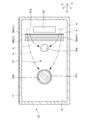
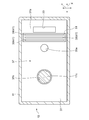
- (First embodiment) 1 and 2 show a configuration of a gear device 10 according to the first embodiment.
- the gear device 10 is installed such that the axial direction of the output shaft 17c is the vertical direction.
- the gear device 10 is an orthogonal shaft reducer, and includes a box-shaped casing 11 and a lubricating oil passage 37.
- the casing 11 is integrally provided with a flat plate-like road member 31 and is formed by casting a metal material. Note that the casing 11 does not have to be formed integrally with all the parts, and may be configured by combining a plurality of divided bodies.
- the passage member 31 may be separated from the casing 11 and the passage member 31 may be fixed to the casing 11.
- the inner space of the casing 11 is vertically divided by a passage member 31.
- the casing 11 has a storage space 13 below the passage member 31 and an upper ceiling space 15.
- the storage space 13 accommodates a plurality of gears 13a to 13d, and the lubricating oil 16 is stored therebelow.
- the casing 11 is provided with an inspection port 19 for inspecting the inside.
- the inspection port 19 is opened and closed by a lid member 23, and the lid member 23 is detachably attached to the casing 11 with screws.
- an input shaft 17a, a gear shaft 17b, and an output shaft 17c are provided in the casing 11.
- the input shaft 17a is rotatably supported by the casing 11 via the first bearing 18a, and the first bevel gear 13a is fixed thereto.
- the first bevel gear 13 a is installed by being partially immersed in the lubricating oil 16.
- the gear shaft 17b is rotatably supported by the casing 11 via the second bearing 18b, and the second bevel gear 13b and the first small-diameter gear 13c are fixed.
- the output shaft 17c is rotatably supported by the casing 11 via the third bearing 18c, and the first large-diameter gear 13d is fixed thereto.
- the input shaft 17a is connected to a motor (not shown).
- the shafts 17a to 17c are engaged with the gears 13a to 13d.
- Rotating plate 13i is fixed to input shaft 17a adjacent to first bevel gear 13a.
- the rotating plate 13 i has a larger diameter than the first bevel gear 13 a, and a part of the rotating plate 13 i is immersed in the lubricating oil 16.
- the rotating plate 13i rotates together with the input shaft 17a, the lubricating oil 16 attached to the rotating plate 13i is lifted upward.
- the passage member 31 includes an introduction port 33, a first discharge port 35a, and a second discharge port 35b.
- the introduction port 33 is provided above the rotating plate 13i and is formed in a rectangular shape.
- the first discharge port 35a is provided above the gear shaft 17b and the second bearing 18b and is formed in a circular shape.
- the 2nd discharge port 35b is provided above the 3rd bearing 18c, is formed in circular shape, and the output shaft 17c penetrates.
- Lubricating oil flow path 37 is formed on the upper surface of passage member 31.
- the lubricating oil 16 stored in the casing 11 is splashed by the rotation of the rotating plate 13 i, and the lubricating oil 16 is sent to the lubricating oil flow path 37 through the introduction port 33.
- Part of the lubricating oil 16 flows from the introduction port 33 to the discharge ports 35a and 35b, drops from the first discharge port 35a to the second bearing 18b and the second bevel gear 13b, and from the second discharge port 35b to the third bearing. It is dripped at 18c.
- An arrow A indicated by a two-dot chain line in FIG. 2 shows an example of a direction in which the lubricating oil 16 flows.
- the rotating plate 13 i serves as an oil feeding means for sending the lubricating oil 16 stored in the casing 11 to the lubricating oil flow path 37 thereabove.
- the lubricating oil 16 is also splashed by the rotation of the first bevel gear 13a. Therefore, when sufficient lubricating oil 16 can be supplied to the inlet 33 by the rotation of the first bevel gear 13a, the rotating plate 13i need not be provided.
- the direction from the inlet 33 to the outlets 35a and 35b is defined as the X direction
- the horizontal direction orthogonal to the X direction is defined as the Y direction.
- the lubricating oil flow path 37 is provided with a plurality of accumulation portions 39 on the upper surface of the passage member 31 that is the flow path surface 37a.
- the accumulation part 39 is provided between the introduction port 33 of the passage member 31 and the discharge ports 35a and 35b.
- the accumulation part 39 is configured by a groove 41 extending in a direction intersecting the direction in which the lubricating oil 16 flows through the lubricating oil flow path 37.
- the groove 41 is formed integrally with the passage member 31.
- the accumulation part 39 is provided below the inspection port 19. That is, the depositing part 39 is provided at a position that is visible from the inspection port 19.
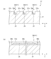
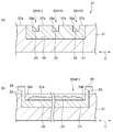
- FIG. 3A shows a front cross-sectional view of the deposition portion 39
- FIG. 3B shows a side cross-sectional view.
- the groove 41 of the deposition part 39 is provided so as to be recessed from the flow path surface 37 a on both sides in the X direction connected to the surface of the groove 41.
- the accumulation part 39 has a front wall surface 39a provided on the front side in the direction in which the lubricating oil 16 flows, and side wall surfaces 39b provided on both sides in the Y direction.
- the front wall surface 39a and the side wall surface 39b are provided substantially vertically.
- Lubricating oil 16 contains metal powder such as iron powder generated by wear and foreign matter 25 such as metal fragments.
- the foreign material 25 having a specific gravity greater than that of the lubricating oil 16 is carried along the lubricating oil flow path 37 while rolling on the flow path surface 37 a on the flow of the lubricating oil 16.
- the foreign material 25 sinks and accumulates in the groove 41. Even if the flow of the lubricating oil 16 occurs in the groove 41, the foreign material 25 is blocked by the front wall surface 39a and the side wall surface 39b, and the escape of the foreign material 25 is suppressed.
- the foreign matter 25 is deposited on the accumulation portion 39 and captured, so that the foreign matter 25 in the lubricating oil 16 can be effectively captured and the foreign matter 25 is captured. It is easy and economical. In addition, the foreign matter 25 accumulated in the accumulation portion 39 can be easily removed by suction, picking, wiping, etc., and is excellent in maintainability. Further, since the depositing portion 39 is provided at a position visible from the inspection port 19, it is possible to easily confirm the accumulation state of the foreign matter 25, and the wear state of the gears 13a to 13d and the like can be easily estimated from the accumulation amount.
- the accumulation portion 39 is provided on the upper surface of the passage member 31 at a low cost.
- the groove 41 of the accumulation portion 39 is recessed from the flow path surface 37a, the foreign matter 25 can be captured without significantly impeding the flow of the lubricating oil 16 in the lubricating oil flow path 37.
- the front wall surface 39a of the accumulation part 39 may incline with the ascending slope or the descending slope toward the front side in the direction in which the foreign matter 25 flows.
- the inclination angle with respect to the vertical plane is preferably, for example, 0 ° to 45 °, and more preferably 0 ° to 30 °.
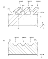
- FIG. 4A shows a perspective cross-sectional view of a deposition portion 39 as a first modification.
- the accumulation part 39 may be configured by a convex part 43 provided on the flow path surface 37a.
- the convex portion 43 is provided as a ridge extending in the Y direction.
- the convex portion 43 is provided so as to protrude above the flow path surfaces 37 a on both sides in the X direction connected to the surface of the convex portion 43.
- the convex portion 43 is formed in a triangular shape, a semicircular shape, or the like in addition to a rectangular shape.
- the convex portions 43 as the protrusions and the concave portions as the grooves 41 may be formed to extend in a curved shape, a wavy shape or the like in addition to the linear shape.
- FIG. 4B shows a front cross-sectional view of the deposition portion 39 as a second modification.
- the deposition part 39 may be constituted by a concave part as the depression 45.
- the depositing part 39 may be composed of a convex part as a protrusion.
- These concave portions and convex portions are formed in, for example, a hemispherical shape, a columnar shape, a conical shape, or the like.
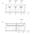
- FIG. 5 shows a deposition part 39 as a third modification.
- a magnet 47 is installed on the groove bottom surface, which is the surface of the groove 41.
- the magnet 47 is installed along the Y direction in which the groove 41 extends.
- the magnet 47 is composed of a permanent magnet such as a ferrite magnet.
- the installation location of the magnet 47 is not particularly limited as long as it is the surface of the groove 41. Further, when the depositing part 39 is composed of the convex part 43, the magnet 47 may be installed on the surface of the convex part 43. In addition, the magnet 47 may be detachably installed on the deposition unit 39. If the magnet 47 is removed from the accumulation part 39, the foreign material 25 attracted to the magnet 47 can be easily removed outside the casing 11.
- the gear device 10 further includes a foreign matter capturing member 51.
- the foreign matter capturing member 51 is formed in a flat plate shape that is long in the Y direction.
- the foreign matter capturing member 51 is made of a resin material, but may be made of a metal material or the like.
- the foreign matter capturing member 51 is provided separately from the passage member 31.
- a groove-like fitting portion 49 that is long in the Y direction is formed in the passage member 31, and the foreign matter capturing member 51 is fitted into the fitting portion 49. That is, the foreign material capturing member 51 is detachably attached to the passage member 31.
- the upper surface of the foreign material capturing member 51 is provided substantially flush with the upper surface of the passage member 31.
- Lubricating oil flow path 37 is formed on the upper surface of passage member 31 and foreign material capturing member 51. Unlike the first embodiment, the accumulation unit 39 is provided not on the upper surface of the passage member 31 but on the upper surface of the foreign matter capturing member 51. Except for this point, the shape of the deposition part 39 is the same as that of the first embodiment.
- the foreign matter capturing member 51 includes a standing portion 53 provided upward from both sides in the Y direction, and a grip portion 55 projecting laterally from each standing portion 53. If the operator grips the grip portion 55 and lifts the foreign material capturing member 51, the foreign material capturing member 51 can be easily removed from the passage member 31.
- the gear device 10 since the accumulation portion 39 is provided on the upper surface of the foreign matter capturing member 51, the foreign matter 25 accumulated on the accumulation portion 39 is removed from the passage member 31 by removing the foreign matter capturing member 51 from the casing. 11 can be easily removed.
- the foreign material capture member 51 may be a disk shape or the like as long as it is a plate shape, or may be another shape.
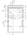
- (Third embodiment) 8 and 9 show the configuration of the gear device 10 according to the third embodiment.
- the gear device 10 is a parallel shaft speed reducer.
- the gear device 10 is installed such that the axial direction of the output shaft 17c is the horizontal direction.
- the input shaft 17a is supported on the casing 11 via the first bearing 18a, and the second small diameter gear 13e is fixed thereto.
- the gear shaft 17b is supported by the casing 11 via the second bearing 18b, and the second large diameter gear 13f and the third small diameter gear 13g are fixed thereto.
- the output shaft 17c is supported by the casing 11 via the third bearing 18c, and the third large-diameter gear 13h is fixed.
- the gears 13e to 13h are engaged with each other.
- the passage member 31 is not formed with the introduction port 33.
- a suction pipe 65 having an oil supply port 61 provided in the storage space 13 and an oil discharge port 63 provided in the ceiling space 15 is connected to the casing 11.
- the suction pipe 65 is provided with a pump 67 in the middle of the suction pipe 65, and by driving the pump 67, the lubricating oil 16 is sent from the oil supply port 61 through the oil discharge port 63 to the lubricating oil passage 37. That is, the pump 67 serves as an oil feeding means for sending the lubricating oil 16 through the suction pipe 65 to the lubricating oil flow path 37.
- the third small diameter gear 13g is not immersed in the lubricating oil 16, and the third discharge port 35c is formed above the gear 13g.
- a fourth discharge port 35d is formed above the shafts 17a to 17c in the vicinity of the bearings 18a to 18c.
- a part of the lubricating oil 16 sent to the lubricating oil flow path 37 by the suction pipe 65 is dropped onto the gear 13g from the third discharge port 35c.
- a part of the lubricating oil 16 is dropped from the fourth discharge port 35d to the shafts 17a to 17c and is transmitted from the surfaces of the shafts 17a to 17c to the bearings 18a to 18c.
- the discharge ports 35a to 35d of the passage member 31 are provided at positions corresponding to the positions of the gears 13a to 13g and the bearings 18a to 18c to be lubricated.
- a discharge port may also be provided above the meshing portion of the gear 13e and the gear 13f, and the lubricating oil 16 in the lubricating oil flow path 37 may be dropped onto the meshing portion through the discharge port.
- the accumulation portion 39 is provided in the vicinity of the oil supply port 61 of the passage member 31, that is, on the inflow side of the lubricating oil 16 of the passage member 31.
- the parallel shaft gear reducer and the orthogonal shaft gear reducer have been described as the gear device 10.
- the type of the reduction mechanism is not particularly limited. A dynamic gear mechanism may be used.
- the rotating plate 13i fixed to the input shaft 17a is adopted as the oil feeding means
- the pump is used as the oil feeding means. 67 was adopted.
- the present invention is not limited to this, and the pump 67 may be adopted as the oil feeding means in the gear devices of the first embodiment and the second embodiment, or the rotary plate 13i as the oil feeding means in the gear device of the third embodiment. May be adopted.
- the rotating plate 13i When the rotating plate 13i is employed in the gear device of the third embodiment, the rotating plate 13i is fixed to the input shaft 17a, and the introduction port 33 is provided above the rotating plate 13i. Further, a partition wall is installed around the introduction port 33 so that the lubricating oil 16 supplied from the introduction port 33 to the passage member 31 is guided along the partition wall and is supplied to the upstream side of the accumulation portion 39. Good. Further, the oil feeding means is not limited to the rotating plate 13 i and the pump 67 as long as it can send the lubricating oil 16 in the casing 11 to the lubricating oil flow path 37.
- Lubricating oil 16 may be sent to a predetermined position other than the gear and the bearing by the lubricating oil passage 37.
- the lubricating oil flow path 37 is configured so that the lubricating oil 16 stored in the storage space 13 is fed by the oil feeding means until the lubricating oil 16 passes through to reach a predetermined position. It may be formed other than.
- the present invention relates to a gear device such as a speed reducer.
Landscapes
- Engineering & Computer Science (AREA)
- General Engineering & Computer Science (AREA)
- Mechanical Engineering (AREA)
- General Details Of Gearings (AREA)
Abstract
L'invention concerne un dispositif à engrenages comportant : un canal d'huile de lubrification (37) qui est ménagé au sein d'un boîtier (11) destiné à loger des engrenages (13a-13d); un moyen de distribution d'huile qui distribue de l'huile de lubrification (16) contenue au sein du boîtier (11) au canal d'huile de lubrification (37); et une section d'accumulation (39) qui est ménagée dans le canal d'huile de lubrification (37) et dans lequel s'accumulent les matières étrangères dans l'huile de lubrification (16) s'écoulant à travers le canal d'huile de lubrification (37). Une structure pour la capture des matières étrangères peut être simplifiée parce que les matières étrangères sont capturées en permettant aux matières étrangères de s'accumuler dans la section d'accumulation (39), et, par conséquent, le dispositif à engrenages possède une efficacité économique élevée. En outre, le dispositif à engrenages peut être extrêmement facile à entretenir parce que les matières étrangères accumulées dans la section d'accumulation (39) peuvent être facilement retirées par aspiration, ramassage ou essuyage.
Priority Applications (1)
| Application Number | Priority Date | Filing Date | Title |
|---|---|---|---|
| CN201380073164.0A CN104995437B (zh) | 2013-03-26 | 2013-12-06 | 齿轮装置 |
Applications Claiming Priority (2)
| Application Number | Priority Date | Filing Date | Title |
|---|---|---|---|
| JP2013-063917 | 2013-03-26 | ||
| JP2013063917A JP6275392B2 (ja) | 2013-03-26 | 2013-03-26 | 歯車装置 |
Publications (1)
| Publication Number | Publication Date |
|---|---|
| WO2014155453A1 true WO2014155453A1 (fr) | 2014-10-02 |
Family
ID=51622552
Family Applications (1)
| Application Number | Title | Priority Date | Filing Date |
|---|---|---|---|
| PCT/JP2013/007182 Ceased WO2014155453A1 (fr) | 2013-03-26 | 2013-12-06 | Dispositif à engrenages |
Country Status (3)
| Country | Link |
|---|---|
| JP (1) | JP6275392B2 (fr) |
| CN (1) | CN104995437B (fr) |
| WO (1) | WO2014155453A1 (fr) |
Cited By (2)
| Publication number | Priority date | Publication date | Assignee | Title |
|---|---|---|---|---|
| EP3901491A1 (fr) * | 2020-04-24 | 2021-10-27 | RENAULT s.a.s. | Goulotte de lubrification gravitaire a retention de particules |
| WO2023066421A1 (fr) * | 2021-10-18 | 2023-04-27 | Schaeffler Technologies AG & Co. KG | Bac d'égouttage d'huile, engrenage planétaire et transmission d'essieu électrique |
Families Citing this family (4)
| Publication number | Priority date | Publication date | Assignee | Title |
|---|---|---|---|---|
| CN106402360A (zh) * | 2016-11-10 | 2017-02-15 | 上海应用技术大学 | 自清理金属杂质的减速器 |
| CN115355336B (zh) | 2018-05-31 | 2026-01-02 | 株式会社电装 | 阀装置 |
| CN109737199B (zh) * | 2018-12-30 | 2020-11-10 | 青岛绿捷通达新能源科技有限公司 | 一种变速器及混动汽车 |
| CN113700802A (zh) * | 2021-08-16 | 2021-11-26 | 珠海格力电器股份有限公司 | 一种曲柄组件、减速器和机器人 |
Citations (6)
| Publication number | Priority date | Publication date | Assignee | Title |
|---|---|---|---|---|
| JPS53101170U (fr) * | 1977-01-19 | 1978-08-15 | ||
| JPS6215652U (fr) * | 1985-07-15 | 1987-01-30 | ||
| JPH0586060U (ja) * | 1992-04-23 | 1993-11-19 | 三菱自動車工業株式会社 | 油浴潤滑式の歯車装置 |
| JPH09210185A (ja) * | 1996-02-05 | 1997-08-12 | Mazda Motor Corp | 変速機の潤滑装置 |
| JP2006300242A (ja) * | 2005-04-21 | 2006-11-02 | Sumitomo Heavy Ind Ltd | 減速機及び減速機用ケーシング |
| EP2199645A1 (fr) * | 2008-12-19 | 2010-06-23 | Getrag Ford Transmissions GmbH | Rainure de lubrification pour un engrenage et procédé de fabrication de la rainure de lubrification |
Family Cites Families (7)
| Publication number | Priority date | Publication date | Assignee | Title |
|---|---|---|---|---|
| JPH07217725A (ja) * | 1994-02-04 | 1995-08-15 | Toyota Motor Corp | 差動装置の潤滑構造 |
| JP3133219B2 (ja) * | 1994-07-21 | 2001-02-05 | ダイハツ工業株式会社 | 動力伝達装置の潤滑構造 |
| JP2009174682A (ja) * | 2008-01-28 | 2009-08-06 | Jtekt Corp | ディファレンシャル装置の潤滑構造 |
| CN201202954Y (zh) * | 2008-06-25 | 2009-03-04 | 王庆辉 | 主轴轴承油润滑装置 |
| JP2012189178A (ja) * | 2011-03-11 | 2012-10-04 | Showa Corp | 減速装置及びモータ付デファレンシャル装置 |
| JP2012255493A (ja) * | 2011-06-09 | 2012-12-27 | Gkn Driveline Japan Ltd | 動力伝達装置 |
| CN103256467B (zh) * | 2012-02-15 | 2015-08-26 | 鹏驰五金制品(昆山)有限公司 | 一种集中供油系统 |
-
2013
- 2013-03-26 JP JP2013063917A patent/JP6275392B2/ja active Active
- 2013-12-06 CN CN201380073164.0A patent/CN104995437B/zh active Active
- 2013-12-06 WO PCT/JP2013/007182 patent/WO2014155453A1/fr not_active Ceased
Patent Citations (6)
| Publication number | Priority date | Publication date | Assignee | Title |
|---|---|---|---|---|
| JPS53101170U (fr) * | 1977-01-19 | 1978-08-15 | ||
| JPS6215652U (fr) * | 1985-07-15 | 1987-01-30 | ||
| JPH0586060U (ja) * | 1992-04-23 | 1993-11-19 | 三菱自動車工業株式会社 | 油浴潤滑式の歯車装置 |
| JPH09210185A (ja) * | 1996-02-05 | 1997-08-12 | Mazda Motor Corp | 変速機の潤滑装置 |
| JP2006300242A (ja) * | 2005-04-21 | 2006-11-02 | Sumitomo Heavy Ind Ltd | 減速機及び減速機用ケーシング |
| EP2199645A1 (fr) * | 2008-12-19 | 2010-06-23 | Getrag Ford Transmissions GmbH | Rainure de lubrification pour un engrenage et procédé de fabrication de la rainure de lubrification |
Cited By (4)
| Publication number | Priority date | Publication date | Assignee | Title |
|---|---|---|---|---|
| EP3901491A1 (fr) * | 2020-04-24 | 2021-10-27 | RENAULT s.a.s. | Goulotte de lubrification gravitaire a retention de particules |
| FR3109619A1 (fr) * | 2020-04-24 | 2021-10-29 | Renault | Goulotte de lubrification gravitaire a retention de particules |
| WO2023066421A1 (fr) * | 2021-10-18 | 2023-04-27 | Schaeffler Technologies AG & Co. KG | Bac d'égouttage d'huile, engrenage planétaire et transmission d'essieu électrique |
| US12352349B2 (en) | 2021-10-18 | 2025-07-08 | Schaeffler Technologies AG & Co. KG | Oil drip pan, planetary gearing and electric axle drive train |
Also Published As
| Publication number | Publication date |
|---|---|
| JP6275392B2 (ja) | 2018-02-07 |
| CN104995437A (zh) | 2015-10-21 |
| JP2014190358A (ja) | 2014-10-06 |
| CN104995437B (zh) | 2018-09-25 |
Similar Documents
| Publication | Publication Date | Title |
|---|---|---|
| JP6275392B2 (ja) | 歯車装置 | |
| CN113316694B (zh) | 变速器装置 | |
| JP6351624B2 (ja) | 垂直方向に段階的な、隣接する2つのギアトレインを潤滑するための機構 | |
| JP6580047B2 (ja) | 給油路を有する車両動力伝達ユニット(ptu) | |
| JP6210200B2 (ja) | 車両用変速機のオイル供給装置 | |
| CN105909956B (zh) | 润滑结构和变速器 | |
| EP2148114A1 (fr) | Appareil de lubrification et transmission équipée de celui-ci | |
| US11662013B2 (en) | Stalactite passive lubrication system | |
| CN106461060A (zh) | 变速器装置 | |
| CN108930779A (zh) | 变速器的润滑结构 | |
| KR102373086B1 (ko) | 진공 펌프 | |
| US10174829B2 (en) | Foreign matter attracting structure | |
| JP5821781B2 (ja) | 転がり軸受装置 | |
| JP2010031882A (ja) | 潤滑装置およびそれを備えた変速機 | |
| CN202768644U (zh) | 轴承润滑装置及工程机械 | |
| JP7427324B2 (ja) | 回転機械 | |
| JP2015132314A (ja) | ディファレンシャル装置の潤滑構造 | |
| JP2016191438A (ja) | オイルリング式すべり軸受 | |
| CN118009024A (zh) | 减速器及车辆 | |
| EP4082902A1 (fr) | Structure de lubrification de transmission d'hélicoptère | |
| CN108351018A (zh) | 油导引罩和配备有油导引罩的传动设施 | |
| JP6069164B2 (ja) | 変速機 | |
| CN104712737B (zh) | 具有壳体的减速器 | |
| JP2017082865A (ja) | 動力伝達装置の潤滑油供給構造 | |
| CN202414888U (zh) | 钢丝、电缆涂油装置 |
Legal Events
| Date | Code | Title | Description |
|---|---|---|---|
| 121 | Ep: the epo has been informed by wipo that ep was designated in this application |
Ref document number: 13880559 Country of ref document: EP Kind code of ref document: A1 |
|
| NENP | Non-entry into the national phase |
Ref country code: DE |
|
| 122 | Ep: pct application non-entry in european phase |
Ref document number: 13880559 Country of ref document: EP Kind code of ref document: A1 |