WO2014155582A1 - Dispositif de joint d'écubier d'embossage - Google Patents
Dispositif de joint d'écubier d'embossage Download PDFInfo
- Publication number
- WO2014155582A1 WO2014155582A1 PCT/JP2013/059097 JP2013059097W WO2014155582A1 WO 2014155582 A1 WO2014155582 A1 WO 2014155582A1 JP 2013059097 W JP2013059097 W JP 2013059097W WO 2014155582 A1 WO2014155582 A1 WO 2014155582A1
- Authority
- WO
- WIPO (PCT)
- Prior art keywords
- seal ring
- liner
- stern
- lubricating oil
- housing
- Prior art date
- Legal status (The legal status is an assumption and is not a legal conclusion. Google has not performed a legal analysis and makes no representation as to the accuracy of the status listed.)
- Ceased
Links
Images



Classifications
-
- B—PERFORMING OPERATIONS; TRANSPORTING
- B63—SHIPS OR OTHER WATERBORNE VESSELS; RELATED EQUIPMENT
- B63H—MARINE PROPULSION OR STEERING
- B63H23/00—Transmitting power from propulsion power plant to propulsive elements
- B63H23/32—Other parts
- B63H23/36—Shaft tubes
-
- B—PERFORMING OPERATIONS; TRANSPORTING
- B63—SHIPS OR OTHER WATERBORNE VESSELS; RELATED EQUIPMENT
- B63H—MARINE PROPULSION OR STEERING
- B63H23/00—Transmitting power from propulsion power plant to propulsive elements
- B63H23/32—Other parts
- B63H23/321—Bearings or seals specially adapted for propeller shafts
-
- F—MECHANICAL ENGINEERING; LIGHTING; HEATING; WEAPONS; BLASTING
- F16—ENGINEERING ELEMENTS AND UNITS; GENERAL MEASURES FOR PRODUCING AND MAINTAINING EFFECTIVE FUNCTIONING OF MACHINES OR INSTALLATIONS; THERMAL INSULATION IN GENERAL
- F16J—PISTONS; CYLINDERS; SEALINGS
- F16J15/00—Sealings
- F16J15/002—Sealings comprising at least two sealings in succession
- F16J15/006—Sealings comprising at least two sealings in succession with division of the pressure
-
- F—MECHANICAL ENGINEERING; LIGHTING; HEATING; WEAPONS; BLASTING
- F16—ENGINEERING ELEMENTS AND UNITS; GENERAL MEASURES FOR PRODUCING AND MAINTAINING EFFECTIVE FUNCTIONING OF MACHINES OR INSTALLATIONS; THERMAL INSULATION IN GENERAL
- F16J—PISTONS; CYLINDERS; SEALINGS
- F16J15/00—Sealings
- F16J15/16—Sealings between relatively-moving surfaces
- F16J15/162—Special parts or details relating to lubrication or cooling of the sealing itself
-
- F—MECHANICAL ENGINEERING; LIGHTING; HEATING; WEAPONS; BLASTING
- F16—ENGINEERING ELEMENTS AND UNITS; GENERAL MEASURES FOR PRODUCING AND MAINTAINING EFFECTIVE FUNCTIONING OF MACHINES OR INSTALLATIONS; THERMAL INSULATION IN GENERAL
- F16J—PISTONS; CYLINDERS; SEALINGS
- F16J15/00—Sealings
- F16J15/16—Sealings between relatively-moving surfaces
- F16J15/32—Sealings between relatively-moving surfaces with elastic sealings, e.g. O-rings
- F16J15/324—Arrangements for lubrication or cooling of the sealing itself
-
- F—MECHANICAL ENGINEERING; LIGHTING; HEATING; WEAPONS; BLASTING
- F16—ENGINEERING ELEMENTS AND UNITS; GENERAL MEASURES FOR PRODUCING AND MAINTAINING EFFECTIVE FUNCTIONING OF MACHINES OR INSTALLATIONS; THERMAL INSULATION IN GENERAL
- F16J—PISTONS; CYLINDERS; SEALINGS
- F16J15/00—Sealings
- F16J15/16—Sealings between relatively-moving surfaces
- F16J15/32—Sealings between relatively-moving surfaces with elastic sealings, e.g. O-rings
- F16J15/3244—Sealings between relatively-moving surfaces with elastic sealings, e.g. O-rings with hydrodynamic pumping action
-
- B—PERFORMING OPERATIONS; TRANSPORTING
- B63—SHIPS OR OTHER WATERBORNE VESSELS; RELATED EQUIPMENT
- B63H—MARINE PROPULSION OR STEERING
- B63H23/00—Transmitting power from propulsion power plant to propulsive elements
- B63H23/32—Other parts
- B63H23/321—Bearings or seals specially adapted for propeller shafts
- B63H2023/327—Sealings specially adapted for propeller shafts or stern tubes
Definitions
- the present invention uses a marine vessel propulsion shaft that passes through a housing provided on the outside of a stern tube and a seal ring that prevents seawater from entering the inside of the vessel.
- the present invention relates to a stern tube sealing device.
- seal rings made of rubber or elastomer have been used in stern tube sealing devices.
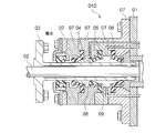
- lip-type seal rings 04, 05 which are made of an elastic member slidably contacted with a liner 03 attached to a propulsion shaft (propeller shaft) 02 that penetrates the stern tube 01.
- the first seal ring 04 disposed on the stern side and the second seal ring 05 adjacent to the first seal ring 04 are disposed so as to be sandwiched between the plurality of housing members 07, and a first stern annular space 08 is formed.
- the stern tube seal device 010 prevents the inundation of seawater, intrusion of foreign matter, and leakage of lubricating oil inside the ship by forming a second stern annular space 09 by the second seal ring 05 and the third seal ring 06. Is disclosed.
- the cross-sectional shape of the first seal ring 04 disclosed in Patent Document 1 is such that the seawater in the first stern annular space 08 is formed on the sliding contact surface where the seal ring 04 contacts the liner 03 when the propeller shaft 02 rotates.
- fine irregularities are provided so as to forcibly send out the high-pressure side out of the ship, and the sending action is positively generated when the propeller shaft 02 rotates.
- the frictional heat generated by the rotation of the propeller shaft 02 partially exceeds 150 ° C. at the sliding contact portion where the seal ring 04 contacts the liner 03. It has been.
- NBR Nirile Butadiene Rubber
- fluorine rubber or the like having high heat resistance
- the present invention has been made in view of the above-described problems, and is a stern tube that cools and lubricates the sliding contact portion of the first seal ring with the liner to prevent wear and improve the durability of the seal ring.
- An object is to provide a sealing device.
- the present invention is a stern tube sealing device constituted by a plurality of seal rings that are in contact with an outer peripheral surface of a liner of a propeller shaft that rotatably supports a propeller mounted on a stern of a ship, A housing that externally fits the liner and holds the plurality of seal rings; A first seal ring disposed on the most stern side of the plurality of seal rings; A second seal ring disposed on the ship front side of the first seal ring with a distance from the first seal ring; A nozzle that ejects lubricating oil that cools the first seal ring,
- the stern tube sealing device can be provided in which the nozzle for ejecting the lubricating oil of the nozzle is disposed in the vicinity of the sliding contact portion between the liner and the first seal ring.
- the first seal ring is effectively cooled by the lubricating oil sprayed from the jet outlet by the frictional heat generated by sliding at the peripheral contact portion between the first seal ring and the liner.
- a spiral groove is formed on a surface of the housing facing the liner and in the vicinity of the jet outlet in a direction in which the lubricating oil is pushed out toward the stern annular space with the forward rotation of the liner. It is good to provide.
- the lubricating oil is extruded to the stern annular space side, and the circumferential contact portion between the first seal ring and the liner is cooled.
- the cooling effect can be improved by making the lubricating oil to be easily ejected from the ejection port.
- the nozzle is formed in the housing.
- the nozzle in the housing, it is possible to accurately inject the lubricating oil onto the circumferential contact portion between the first seal ring and the liner, and the cooling effect can be improved.
- the nozzle is disposed in the first seal ring.
- the internal heat storage can be cooled, and the cooling efficiency of the first seal ring is further improved.
- the nozzle has a gap portion where the introduction port opens into a lubricating oil passage in the housing, and the lubricating oil passage communicating with the jet port faces the housing and the liner. It is good to be formed with the cylindrical member arrange
- the cylindrical nozzle is arranged in the gap between the housing and the liner, the nozzle arrangement structure is simplified, the manufacturing cost is reduced, and the product accuracy associated with the simplified structure is achieved. Can be improved, and can be accurately sprayed onto the sliding contact portion of the first seal ring, so that the sliding contact portion can be efficiently cooled.
- a radial portion of the liner is formed between the propeller shaft, a space portion formed by the liner fitted to the propeller shaft, the first seal ring, and the jet port.
- the lubricating oil that has cooled the sliding contact portion may be returned to the stern annular space through the space portion.
- the lubricating oil that has cooled the sliding contact portion is returned to the stern annular space through the space portion between the liner and the propeller shaft, so that the lubricating oil pressure between the injection port and the sliding contact portion is high.
- the introduction port for the lubricating oil ejected from the ejection port is open at a right angle to the lubricating oil flow direction of the lubricating oil passage in the housing.
- the lubricating oil can easily enter the nozzle. Therefore, the amount of lubricating oil ejected from the ejection port increases, and the cooling efficiency of the first seal ring is improved.
- a stern tube sealing device that improves the durability of the seal ring by intensively cooling the sliding contact portion of the first seal ring with the liner with the lubricating oil ejected from the nozzle. it can.
- FIG. 1 shows a schematic cross-sectional view of a stern tube sealing device in which the present invention is implemented.
- the principal part expanded sectional view of 1st Embodiment of this invention is shown.
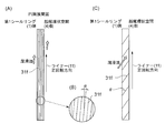
- (A) is a development view in the circumferential direction of a thread groove provided on the surface of the housing facing the liner of FIG. 2
- (B) is a partial enlarged view of (A)
- (C) is a development view of another shape. Show.
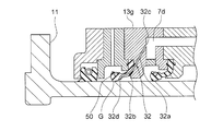
- the principal part expanded sectional view of 2nd Embodiment of this invention is shown.
- the principal part expanded sectional view of 3rd Embodiment of this invention is shown.
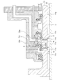
- the principal part expanded sectional view of 4th Embodiment of this invention is shown. It is explanatory drawing of a prior art.
- the stern tube sealing device 12 is provided with a propeller shaft 10 for propulsion of a ship having a propeller 21 attached to the end thereof and a stern tube 15 protruding from the stern tube 15 to the outside of the stern (stern side).
- a housing 13 through which the shaft 10 passes, and seal rings 1, 2, and 3 that seal between the inner peripheral surface of the housing 13 and the outer peripheral side of the liner 11 fitted on the propeller shaft 10 are configured.
- the liner 11 of the propeller shaft 10 is fixed to the propeller 21 by bolts 11a.
- the body portion of the liner 11 surrounds the outer periphery of the propeller shaft 10 and rotates integrally with the propeller shaft 10.
- a lip-shaped first seal ring 1, second seal ring 2, and third seal ring 3 are in sliding contact with the outer periphery of the trunk portion of the liner 11 from the stern side.
- a fishing net prevention ring 14 is attached on the furthermost stern side of the first seal ring 1. The fishing net prevention ring 14 prevents foreign matter in seawater such as a fishing net from entering the stern tube sealing device 12.
- the housing 13 is integrally fixed to the stern tube 15 by bolts 13f, with a plurality of housings 13a to 13e overlapping in a stacked state in the axial direction of the propeller shaft 10.
- the plurality of housings 13a to 13e are arranged in order of the first housing 13a, the second housing 13b, the third housing 13c, the fourth housing 13d, and the fifth housing 13e from the stern side.
- Each of the first, second and third seal rings is fixed in a state of being sandwiched between the housings 13a to 13e.
- the lips of the first seal ring 1 and the second seal ring 2 are directed to the seawater side, and the third seal ring 3 is directed to the bow side.
- seal rings 1, 2, 3 and 18 are made of rubber or elastomer elastic members, and the rubber material is made of fluoro rubber or NBR having excellent water resistance, oil resistance and heat resistance.
- the seal ring has an annular shape, and the cross-sectional shape of the ring portion has a constant cross-sectional shape, and the body portion of the liner 11 is inserted into the hollow portion at the center.
- the first seal ring 1 and the second seal ring 2 form a first stern annular space 4 that is a stern annular space
- the second seal ring 2 and the third seal ring 3 form a second stern annular space 5.
- a stern tube chamber 19 communicating with an oil reservoir tank 27 is formed in the stern tube 15 between the third seal ring 3 and the fourth seal ring 18.
- Lubricating oil is always supplied to the first stern annular space 4 via an oil feed pipe 7 connected to an oil reservoir tank 6 for storing lubricating oil provided in the ship.
- the oil sump tank 6 is adjusted so that the hydraulic pressure in the first stern annular space 4 is lower than the axial draft pressure.
- the oil reservoir tank 6 is provided with a replenishment line 28 for replenishing the lubricating oil and a valve 29 for adjusting the lubrication oil replenishment when the lubricating oil in the oil reservoir tank 6 decreases.
- the second stern annular space 5 includes an air vent line 8 that communicates with the atmosphere, and a drain that collects the stern tube bearing lubricating oil (the lubricating oil in the first stern annular space 4 and the stern tube chamber 19) in the event of leakage.
- Line 9 is connected.
- 48 is a drain tank. Since the second stern annular space 5 is open to the atmosphere, the pressure in the stern tube chamber can be independently set lower than the axial draft pressure, so that the pressure in the stern tube chamber 19 can be reduced, and the load on the fourth seal ring 18 is reduced. The durability of the fourth seal ring 18 can be improved.
- the lubricating oil flows through the oil feeding pipe 7 in the stern pipe 15 and the oil passages drilled in the fifth, fourth, and third housings 13e, 13d, and 13c, and the first stern annular space is formed in the third housing 13c. 4 is supplied.
- the lubricating oil flowing through the oil feed pipe 7 and each oil passage is adjusted so that a pressure lower than the axial core draft pressure acts. This is to reduce the load on the first seal ring 1 when the propeller shaft 10 rotates.
- FIG. 2 shows a partially enlarged view of the housing 13 in the present embodiment.
- Each oil passage is drilled in the wall portion of the stern tube 15, and is connected to the first oil passage 7a connected to the oil feeding tube 7, and the second oil passage opened at a position facing the first oil passage 7a of the fifth housing 13e. 7b, a third oil passage 7c opened at a position facing the second oil passage 7b of the fourth housing 13d, and a fourth oil passage 7d opened at a position opposed to the third oil passage 7c of the third housing 13c. It consists of
- the third housing 13c has an inlet 31c that opens to the fourth oil passage 7d and takes in lubricating oil, and extends radially inward in the radial direction continuously to the inlet 31c.
- Axial which is provided with a lubricant outlet 31d in the vicinity of the sliding contact portion G with the liner 11 of the first seal ring 1 and is bent toward the first seal ring 1 side, continuously from the path 31a and the radial oil path 31a.
- a nozzle 31 having a directional oil passage 31b is provided.
- the radial oil passage 31a and the axial oil passage 31b function as a nozzle that injects lubricating oil onto the sliding contact portion G that is in sliding contact with the liner 11 of the first seal ring 1.
- the inlet 31c is opened in a direction perpendicular to the flow of the lubricating oil that flows linearly from the third oil passage 7c to the fourth oil passage 7d. Therefore, the inlet 31c is arranged so that the lubricating oil can easily enter the nozzle 31 by the fluid pressure of the lubricant acting on the inlet 31c.
- the nozzles 31 are provided at a plurality of locations in a ring shape along the outer peripheral surface of the liner 11.
- FIG. 3A is a developed view in the circumferential direction of the inner peripheral surface 31e of FIG. 2A (the surface facing the liner 11 of the housing 13).
- the lubricating oil is moved to the first stern annular space 4 side through a gap R between the housing 13 and the liner 11.
- a spiral groove 31f having a pumping action is formed.
- the spiral groove 31f is formed in a direction in which the lubricating oil is rotated along with the rotation of the liner and pushed toward the first stern annular space 4 when the liner 11 rotates in the forward direction (rotates in the direction in which the ship moves forward).
- the lubricating oil flows along the spiral groove 31f in the direction of ⁇ in FIG.
- a pumping action is exerted on the inner peripheral surface 31e of the housing 13 in the direction in which the lubricating oil is pushed out toward the first stern annular space 4 side. Therefore, the lubricating oil that cools the sliding contact portion G between the first seal ring 1 and the liner 11 is easily ejected from the ejection port 31d, and the cooling effect of the sliding contact portion G can be improved by more lubricating oil. it can.
- the spiral groove 31f is a single spiral groove and has a structure in which the pumping action is slightly suppressed.
- the twist angle ⁇ (lead angle) of the spiral groove 31f is suppressed to 1 to 10 degrees. This is because the amount of the lubricating oil ejected from the ejection port 31d is suppressed by suppressing the twist angle ⁇ to 1 to 10 degrees. If the lubricating oil is ejected more than necessary from the ejection port 31d, the load on the lubricating hydraulic pump increases, leading to an output of the internal combustion engine and fuel consumption loss.
- the suppression of the pumping action prevents the lubricating oil pressure at the sliding contact portion G from being lowered.
- the twist angle ⁇ (lead angle) of the spiral groove 31f is increased as shown in FIG. It is also possible to increase the efficiency.
- Lubricating oil in the oil sump tank 6 flows through the oil feed pipe 7 and each oil passage, and is ejected from the ejection port 31 d of the nozzle 31 toward the sliding contact portion G with the liner 11 of the first seal ring 1.
- the lubricating oil that has cooled the sliding contact portion G with the liner 11 of the first seal ring 1 circulates in the first stern annular space 4, passes through an oil passage and a lubricating oil cooling device (not shown), and reaches an oil reservoir tank.
- the third housing 13c has a shape in which the first stern annular space 4 side of the third housing 13c is expanded in the axial direction and the radial direction in order to provide the nozzle 31 in the third housing 13c.
- the part where the nozzle 31 is not disposed has an action as a backup ring when the pressure acts on the first seal ring 1 from the seawater side, and improves the effect of the part as the seal ring. Can do. Further, since the nozzle 31 for injecting the lubricating oil is disposed in the third housing 13c, the lubricating oil is accurately injected to the sliding contact portion G with the liner 11 of the first seal ring 1, so that the first seal The cooling efficiency of the ring 1 can be improved.
- the present embodiment is the same as the first embodiment except that the nozzle arrangement structure is different. Therefore, the description other than the nozzle forming portion is omitted. Further, the same parts are denoted by the same reference numerals and description thereof is omitted.
- the first seal ring 50 is fixed by the second housing 13b and the third housing 13g.
- the third housing 13g has an inlet 32c that opens into the fourth oil passage 7d and takes in the lubricant, and a first nozzle 32a that forms a lubricant passage drilled to the portion of the first seal ring 50. Is arranged.
- the first seal ring 50 is internally communicated with the lubricating oil passage of the first nozzle 32a, and is opened in the vicinity of the sliding contact portion G that is in sliding contact with the liner 11 of the first seal ring 50.
- a second nozzle 32b having a jet port 32d for injecting oil is formed.
- the first nozzle 32 a and the second nozzle 32 b function as a nozzle 32 that injects lubricating oil to the sliding contact portion G that is in sliding contact with the liner 11 of the first seal ring 50.
- the nozzles 32 composed of the first nozzles 32 a and the second nozzles 32 b are arranged in a plurality of locations in a ring shape along the outer peripheral surface of the liner 11.
- the lubricating oil is accurately applied to the sliding contact portion G of the first seal ring 50 from the first nozzle 32a through the second nozzle 32b formed inside the first seal ring 50. Is injected into. Furthermore, since the lubricating oil passes through the inside of the first seal ring 50, it is possible to easily cool the inside where heat is easily stored, and the first seal ring 50 can be cooled more effectively. One seal ring 50 can be effectively cured and prevented from being worn.
- the present embodiment is the same as the first embodiment except that the nozzle arrangement structure is different. Therefore, the description other than the nozzle forming portion is omitted. Further, the same parts are denoted by the same reference numerals and description thereof is omitted.
- a nozzle 33 is fixed to the third housing 13h at the downstream end of the fourth oil passage 7d.
- the nozzle 33 opens the lubricating oil intake port 33c at the downstream end of the fourth oil passage 7d, and extends in the first stern annular space 4 radially inward in the radial direction center portion 33a.
- the gap portion R between the housing 13h and the liner 11 is bent toward the first seal ring 1, and an outlet 33d for discharging the lubricating oil is opened in the vicinity of the slidable contact portion G that is in sliding contact with the liner 11 of the first seal ring 1. It is formed with the extended axial direction part 33b.
- a notch S in which the axially extending portion 33 b of the nozzle 33 is fitted is disposed in the axial direction.
- the notch S is formed in a semicircular cross section in a direction perpendicular to the axial direction.
- the lubricating oil flows from the downstream end of the fourth oil passage 7d through the radial extending portion 33a and the axial extending portion 33b of the nozzle 33, and from the jet port 33d to the first outlet. Sprayed in the vicinity of the sliding contact portion G that is in sliding contact with the liner 11 of the seal ring 1, the first seal ring 1 can be cooled more effectively, and the first seal ring 1 is effectively cured and prevented from wearing. Can be implemented.
- the present embodiment is the same as the third embodiment except that the lubricating oil that has cooled the sliding contact portion G is returned to the stern annular space by utilizing the space portion V between the liner 11 portion and the propeller shaft 10. . Therefore, the description is omitted except that the lubricating oil that has cooled the sliding contact portion G is returned to the stern annular space. Further, the same parts are denoted by the same reference numerals and description thereof is omitted.
- the nozzle 33 opens the lubricating oil intake port 33 c at the downstream end of the fourth oil passage 7 d, and the inside of the first stern annular space 4 that is the stern annular space is radial.
- a radial direction extending portion 33a extending toward the center in the direction and a gap portion R between the third housing 13h and the liner 11 are bent toward the first seal ring 1 side, and a jet outlet 33d that discharges lubricating oil is provided in the first
- the seal ring 1 is formed by an axially extending portion 33 b opened near the sliding contact portion G that is in sliding contact with the liner 11.
- the liner 11 is externally fitted to the propeller shaft 10 and is fixed to the propeller shaft 10.
- the inner peripheral surfaces of the annular stern-side projection 11f and the bow-side projection 11g projecting toward the propeller shaft 10 and the outer peripheral surface of the propeller shaft 10 are fitted to both ends in the axial direction of the inner peripheral surface of the liner 11. Yes.
- the space portion V between the stern side projection 11 f and the bow side projection 11 g of the liner 11 is an annular space sealed by the outer peripheral surface of the propeller shaft 10.
- first return oil passage 11a communicating with the space V in the radial direction of the liner 11 and the first stern annular space 4 at an intermediate position between the first seal ring 1 of the liner 11 and the jet outlet 33d of the nozzle 33.
- second return oil passage 11b communicating with the space V in the radial direction of the liner 11 and the stern side position of the first return oil passage 11a.
- the propeller shaft 10 protrudes from the liner 11 to the propeller shaft 10 side at the bow side position of the first annular protrusion 11c and the second return oil passage 11b, which protrudes toward the propeller shaft 10 and is fitted on the outer peripheral surface of the propeller shaft 10. And a second annular protrusion 11d that is externally fitted to the outer peripheral surface. And the 3rd oil path 11e formed in a part of space part V used as the cyclic
- the lubricating oil that has cooled the sliding contact portion G passes through the third return oil passage 11e between the liner 11 and the propeller shaft 10 from the plurality of first return oil passages 11a, and then from the plurality of second return oil passages 11d. It flows near the bow side position of the nozzle 33 in the first stern annular space 4.
- the lubricating oil pressure between the injection port 33d and the sliding contact portion G is prevented from becoming too high, and it is easy to ensure the amount of the lubricating oil ejected from the ejection port 33d.
- the heat inside the liner 11 heat from the sliding contact portion
Landscapes
- Engineering & Computer Science (AREA)
- General Engineering & Computer Science (AREA)
- Mechanical Engineering (AREA)
- Chemical & Material Sciences (AREA)
- Combustion & Propulsion (AREA)
- Ocean & Marine Engineering (AREA)
- Physics & Mathematics (AREA)
- Fluid Mechanics (AREA)
- Sealing With Elastic Sealing Lips (AREA)
- Sealing Of Bearings (AREA)
- Sealing Devices (AREA)
Abstract
Priority Applications (5)
| Application Number | Priority Date | Filing Date | Title |
|---|---|---|---|
| CN201380074038.7A CN105189285B (zh) | 2013-03-27 | 2013-03-27 | 船尾管密封装置 |
| JP2015507784A JP6126203B2 (ja) | 2013-03-27 | 2013-03-27 | 船尾管シール装置 |
| KR1020157026555A KR101745234B1 (ko) | 2013-03-27 | 2013-03-27 | 선미관 시일 장치 |
| PCT/JP2013/059097 WO2014155582A1 (fr) | 2013-03-27 | 2013-03-27 | Dispositif de joint d'écubier d'embossage |
| EP13880388.7A EP2979973B1 (fr) | 2013-03-27 | 2013-03-27 | Dispositif de joint d'écubier d'embossage |
Applications Claiming Priority (1)
| Application Number | Priority Date | Filing Date | Title |
|---|---|---|---|
| PCT/JP2013/059097 WO2014155582A1 (fr) | 2013-03-27 | 2013-03-27 | Dispositif de joint d'écubier d'embossage |
Publications (1)
| Publication Number | Publication Date |
|---|---|
| WO2014155582A1 true WO2014155582A1 (fr) | 2014-10-02 |
Family
ID=51622659
Family Applications (1)
| Application Number | Title | Priority Date | Filing Date |
|---|---|---|---|
| PCT/JP2013/059097 Ceased WO2014155582A1 (fr) | 2013-03-27 | 2013-03-27 | Dispositif de joint d'écubier d'embossage |
Country Status (5)
| Country | Link |
|---|---|
| EP (1) | EP2979973B1 (fr) |
| JP (1) | JP6126203B2 (fr) |
| KR (1) | KR101745234B1 (fr) |
| CN (1) | CN105189285B (fr) |
| WO (1) | WO2014155582A1 (fr) |
Cited By (5)
| Publication number | Priority date | Publication date | Assignee | Title |
|---|---|---|---|---|
| CN104828237A (zh) * | 2015-04-23 | 2015-08-12 | 广州科技职业技术学院 | 船舶尾管结构 |
| JP2019065728A (ja) * | 2017-09-29 | 2019-04-25 | 北越工業株式会社 | 油冷式スクリュ圧縮機 |
| CN113247226A (zh) * | 2021-05-11 | 2021-08-13 | 中交广州航道局有限公司 | 一种防艉轴封漏油漏水装置及其使用方法 |
| CN114635967A (zh) * | 2022-03-22 | 2022-06-17 | 中铁工程装备集团有限公司 | 掘进机主驱动密封智能润滑系统及其控制方法 |
| CN116480780A (zh) * | 2023-04-18 | 2023-07-25 | 浙江珂勒曦动力设备股份有限公司 | 组合式密封装置 |
Families Citing this family (9)
| Publication number | Priority date | Publication date | Assignee | Title |
|---|---|---|---|---|
| WO2017122358A1 (fr) * | 2016-01-15 | 2017-07-20 | バルチラジャパン株式会社 | Système d'étanchéité de tube d'étambot, dispositif d'étanchéité de tube d'étambot, navire, et procédé d'étanchéité de tube d'étambot |
| CN105782452B (zh) * | 2016-03-31 | 2017-12-29 | 武汉船用机械有限责任公司 | 一种用于吊舱推进器的艉轴密封结构 |
| CN108825789A (zh) * | 2018-09-06 | 2018-11-16 | 兰州理工大学 | 高速机械密封冷却冲洗装置 |
| CN112888627B (zh) * | 2018-11-20 | 2022-02-11 | 瓦锡兰日本有限公司 | 吃水测量仪和船舶 |
| KR101995781B1 (ko) | 2018-11-23 | 2019-07-03 | (주)한국알앤드디 | 소형 선박 추진기용 부유물 유입방지장치 |
| CN111120658B (zh) * | 2020-01-03 | 2022-04-05 | 湖南永盛船舶有限公司 | 一种可调式船用艉轴密封装置 |
| CN111810641B (zh) * | 2020-06-04 | 2023-03-31 | 江门市鑫辉密封科技有限公司 | 一种密封圈及密封装置 |
| CN116324235A (zh) * | 2020-10-28 | 2023-06-23 | 纳博特斯克有限公司 | 真空密封装置和驱动传递装置 |
| US20260063207A1 (en) * | 2024-08-28 | 2026-03-05 | Caterpillar Inc. | Seal cartridge, seal cartridge assembly, and method of use |
Citations (5)
| Publication number | Priority date | Publication date | Assignee | Title |
|---|---|---|---|---|
| JPH026384B2 (fr) * | 1981-02-20 | 1990-02-08 | Blohm Voss Ag | |
| JPH055341Y2 (fr) * | 1987-11-30 | 1993-02-12 | ||
| JP2909948B2 (ja) * | 1993-05-10 | 1999-06-23 | 三菱重工業株式会社 | 船尾管軸封装置 |
| JP2000238694A (ja) | 1999-02-23 | 2000-09-05 | Nippon Marine Techno Kk | 船尾管シール装置 |
| WO2008099648A1 (fr) * | 2007-02-16 | 2008-08-21 | Nok Corporation | Dispositif d'étanchéité |
Family Cites Families (10)
| Publication number | Priority date | Publication date | Assignee | Title |
|---|---|---|---|---|
| DE884262C (de) * | 1943-07-25 | 1953-07-27 | Voith Gmbh J M | Dichtung mit einer Manschette aus kuenstlichem Gummi |
| US3088744A (en) * | 1960-08-23 | 1963-05-07 | Northrop Corp | Submarine propeller shaft seal |
| JPS4740477Y1 (fr) * | 1970-02-25 | 1972-12-07 | ||
| DE2643769A1 (de) * | 1976-09-29 | 1978-03-30 | Howaldtswerke Deutsche Werft | Abdichtung fuer sich drehende wellen |
| JPS6055600U (ja) * | 1983-09-27 | 1985-04-18 | 三菱重工業株式会社 | 船尾管軸封装置 |
| JP3117332B2 (ja) * | 1993-06-25 | 2000-12-11 | 三菱重工業株式会社 | 船尾管軸封装置 |
| JP2001066757A (ja) * | 2000-08-07 | 2001-03-16 | Seiko Epson Corp | 露光方法 |
| JP3946019B2 (ja) * | 2001-09-18 | 2007-07-18 | 本田技研工業株式会社 | 船舶用ドライブシャフトの軸受け構造 |
| JP5158357B2 (ja) * | 2008-06-09 | 2013-03-06 | Nok株式会社 | 密封装置 |
| DE102008055793B3 (de) * | 2008-11-04 | 2010-09-02 | Voith Patent Gmbh | Vorrichtung zur Abdichtung einer mit einem flüssigen Schmiermittel geschmierten Lagerung |
-
2013
- 2013-03-27 JP JP2015507784A patent/JP6126203B2/ja not_active Expired - Fee Related
- 2013-03-27 WO PCT/JP2013/059097 patent/WO2014155582A1/fr not_active Ceased
- 2013-03-27 EP EP13880388.7A patent/EP2979973B1/fr active Active
- 2013-03-27 KR KR1020157026555A patent/KR101745234B1/ko not_active Expired - Fee Related
- 2013-03-27 CN CN201380074038.7A patent/CN105189285B/zh active Active
Patent Citations (5)
| Publication number | Priority date | Publication date | Assignee | Title |
|---|---|---|---|---|
| JPH026384B2 (fr) * | 1981-02-20 | 1990-02-08 | Blohm Voss Ag | |
| JPH055341Y2 (fr) * | 1987-11-30 | 1993-02-12 | ||
| JP2909948B2 (ja) * | 1993-05-10 | 1999-06-23 | 三菱重工業株式会社 | 船尾管軸封装置 |
| JP2000238694A (ja) | 1999-02-23 | 2000-09-05 | Nippon Marine Techno Kk | 船尾管シール装置 |
| WO2008099648A1 (fr) * | 2007-02-16 | 2008-08-21 | Nok Corporation | Dispositif d'étanchéité |
Non-Patent Citations (1)
| Title |
|---|
| See also references of EP2979973A4 * |
Cited By (6)
| Publication number | Priority date | Publication date | Assignee | Title |
|---|---|---|---|---|
| CN104828237A (zh) * | 2015-04-23 | 2015-08-12 | 广州科技职业技术学院 | 船舶尾管结构 |
| JP2019065728A (ja) * | 2017-09-29 | 2019-04-25 | 北越工業株式会社 | 油冷式スクリュ圧縮機 |
| CN113247226A (zh) * | 2021-05-11 | 2021-08-13 | 中交广州航道局有限公司 | 一种防艉轴封漏油漏水装置及其使用方法 |
| CN113247226B (zh) * | 2021-05-11 | 2022-08-19 | 中交广州航道局有限公司 | 一种防艉轴封漏油漏水装置及其使用方法 |
| CN114635967A (zh) * | 2022-03-22 | 2022-06-17 | 中铁工程装备集团有限公司 | 掘进机主驱动密封智能润滑系统及其控制方法 |
| CN116480780A (zh) * | 2023-04-18 | 2023-07-25 | 浙江珂勒曦动力设备股份有限公司 | 组合式密封装置 |
Also Published As
| Publication number | Publication date |
|---|---|
| JPWO2014155582A1 (ja) | 2017-02-16 |
| KR20150130329A (ko) | 2015-11-23 |
| EP2979973A1 (fr) | 2016-02-03 |
| EP2979973B1 (fr) | 2019-05-08 |
| KR101745234B1 (ko) | 2017-06-08 |
| CN105189285A (zh) | 2015-12-23 |
| EP2979973A4 (fr) | 2016-12-07 |
| JP6126203B2 (ja) | 2017-05-10 |
| CN105189285B (zh) | 2017-03-22 |
Similar Documents
| Publication | Publication Date | Title |
|---|---|---|
| JP6126203B2 (ja) | 船尾管シール装置 | |
| US9841106B2 (en) | Sliding parts | |
| JP2006312936A (ja) | ピストン冷却ノズルの制御された漏出バルブ | |
| JP5881981B2 (ja) | 受動型量制限バルブ | |
| CA2828384C (fr) | Joint segmente a element de regulation de charge axiale | |
| JP2000238694A (ja) | 船尾管シール装置 | |
| JP4755428B2 (ja) | 船舶用推進軸の軸封装置 | |
| US20130017107A1 (en) | Diesel engine fuel injection pump which pistons are sealed with all metal seal rings | |
| US10907681B2 (en) | Pad bearing and rotary machine | |
| CN113404682B (zh) | 径向柱塞泵 | |
| JP6199290B2 (ja) | 船尾管シール装置 | |
| US20110129359A1 (en) | Variable output pump | |
| US20190107033A1 (en) | Valve for adjusting a cooling fluid flow for piston cooling | |
| US8955646B2 (en) | Device for lubricating oil seal of engine | |
| CN104534097A (zh) | 一种动压平衡旋转密封件 | |
| FI122862B (fi) | Mäntäpumppu, jossa on kerrostumasuojaus | |
| JP3668709B2 (ja) | ポッドプロペラ推進システムのシール装置 | |
| CN109209852B (zh) | 活塞泵的杆密封件 | |
| US12564855B2 (en) | High pressure nozzle | |
| US20090151683A1 (en) | Fluid System for Oscillating-Piston Engines | |
| CN207173761U (zh) | 一种履带式装甲车辆用诱导轮曲臂润滑机构 | |
| KR101533613B1 (ko) | 이물질 유입방지유닛을 갖는 스턴튜브 실링장치 | |
| JP2008101594A (ja) | ピストンの潤滑油供給構造及びピストンリング | |
| JP6668790B2 (ja) | 内燃機関のピストン冷却システム及び内燃機関 | |
| CN108050011B (zh) | 一种叶片式液压马达 |
Legal Events
| Date | Code | Title | Description |
|---|---|---|---|
| WWE | Wipo information: entry into national phase |
Ref document number: 201380074038.7 Country of ref document: CN |
|
| 121 | Ep: the epo has been informed by wipo that ep was designated in this application |
Ref document number: 13880388 Country of ref document: EP Kind code of ref document: A1 |
|
| ENP | Entry into the national phase |
Ref document number: 2015507784 Country of ref document: JP Kind code of ref document: A |
|
| WWE | Wipo information: entry into national phase |
Ref document number: 2013880388 Country of ref document: EP |
|
| ENP | Entry into the national phase |
Ref document number: 20157026555 Country of ref document: KR Kind code of ref document: A |
|
| NENP | Non-entry into the national phase |
Ref country code: DE |