WO2014155805A1 - Système de conditionnement d'air pour véhicule - Google Patents
Système de conditionnement d'air pour véhicule Download PDFInfo
- Publication number
- WO2014155805A1 WO2014155805A1 PCT/JP2013/079748 JP2013079748W WO2014155805A1 WO 2014155805 A1 WO2014155805 A1 WO 2014155805A1 JP 2013079748 W JP2013079748 W JP 2013079748W WO 2014155805 A1 WO2014155805 A1 WO 2014155805A1
- Authority
- WO
- WIPO (PCT)
- Prior art keywords
- air
- vehicle
- outlet
- conditioning system
- air conditioning
- Prior art date
- Legal status (The legal status is an assumption and is not a legal conclusion. Google has not performed a legal analysis and makes no representation as to the accuracy of the status listed.)
- Ceased
Links
Images


Classifications
-
- B—PERFORMING OPERATIONS; TRANSPORTING
- B60—VEHICLES IN GENERAL
- B60H—ARRANGEMENTS OF HEATING, COOLING, VENTILATING OR OTHER AIR-TREATING DEVICES SPECIALLY ADAPTED FOR PASSENGER OR GOODS SPACES OF VEHICLES
- B60H1/00—Heating, cooling or ventilating devices
- B60H1/24—Ventilating devices where the heating or cooling is irrelevant
- B60H1/241—Ventilating devices where the heating or cooling is irrelevant characterised by the location of ventilation devices in the vehicle
- B60H1/246—Ventilating devices where the heating or cooling is irrelevant characterised by the location of ventilation devices in the vehicle located in the interior of the vehicle or in or below the floor
-
- B—PERFORMING OPERATIONS; TRANSPORTING
- B60—VEHICLES IN GENERAL
- B60H—ARRANGEMENTS OF HEATING, COOLING, VENTILATING OR OTHER AIR-TREATING DEVICES SPECIALLY ADAPTED FOR PASSENGER OR GOODS SPACES OF VEHICLES
- B60H1/00—Heating, cooling or ventilating devices
- B60H1/00271—HVAC devices specially adapted for particular vehicle parts or components and being connected to the vehicle HVAC unit
- B60H1/00285—HVAC devices specially adapted for particular vehicle parts or components and being connected to the vehicle HVAC unit for vehicle seats
Definitions
- the present invention relates to an air conditioning system for a vehicle that efficiently performs air conditioning between a front seat side and a rear seat side.
- the vehicle air conditioning system 100 shown in FIG. 17 converts the air sucked into the air passage by the blower into the desired conditioned air by the heat exchange unit, and this conditioned air is blown out (the def outlet 111, the vent outlet 112). And from the foot outlet 113).
- the vehicle air conditioning system 100 includes air outlets 111, 112, 113, an air conditioner 110, and a suction duct 120 that extends from the air conditioner 110 to below the front seat 130.
- the suction duct 120 has a front seat lower suction port 121 for sucking conditioned air blown from the blower outlet below the front seat 130.
- the front seat 130 can be preferentially air-conditioned, but in order to blow the conditioned air toward the rear seat 140 side, as shown by a two-dot chain line in FIG.
- the suction duct 120 installation spaces had to be secured.
- An object of the present invention is to provide a vehicle air conditioning system that can be used.
- the present invention has the following characteristics.
- the first feature of the present invention is that an air conditioner that converts air sucked into a blower passage by a blower into a desired conditioned air by a heat exchange unit and blows the air into a passenger compartment, and the heat exchange unit of the blower passage.
- a blow duct having a blowout port that extends from the downstream side to the lower side of the front seat and blows the conditioned air into the vehicle compartment under the front seat, and a wind direction adjusting means that adjusts the direction of the conditioned air blown from the blowout port It is a summary to provide.
- the air outlet is composed of a front air outlet that blows conditioned air toward the front of the vehicle and a rear air outlet that blows conditioned air toward the rear of the vehicle, and the wind direction adjusting means is an air conditioned air that blows out from the front air outlet and the rear air outlet. It is preferable to adjust the air volume.
- the wind direction adjusting means is preferably constituted by an opening / closing member capable of opening and closing the air outlet by the conditioned air passing through the air outlet duct.
- the wind direction adjusting means may include partition means for rotating between a partition position that partitions the lower space of the front seat into a front side and a rear side of the vehicle and an open position that does not partition the front side and the rear side of the vehicle. preferable.
- the partitioning unit is provided apart from the air outlet, and blows air in front of the vehicle when the conditioned air blows at the partition position, and blows the air conditioned air to the rear of the vehicle at the open position by opening the air outlet.
- the partition means preferably has a guide portion that guides the conditioned air to the front of the vehicle at the partition position.
- An expansion / contraction partitioning means that communicates with the blowout duct and is provided below the front seat and extends and contracts in the vertical direction by the conditioned air passing through the blowout duct to partition the space under the front seat into the front side and the rear side of the vehicle. It is preferable to provide.
- the blowout duct includes a main body duct and a tip member that is provided so as to be rotatable with respect to the main body duct and has one blower outlet.
- the wind direction adjusting means rotates the tip member to change the direction of the blower outlet. It is preferable to have switching means for switching to the front or rear of the vehicle.
- the air conditioner has a foot air outlet that blows conditioned air from the front of the vehicle to the lower part of the front seat, and the conditioned air blown from the air outlet to the front of the vehicle is preferably larger than the air conditioned air that blows from the foot air outlet. .
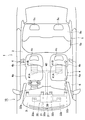
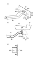
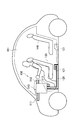
- FIG. 1 is a schematic side view showing the vehicle air conditioning system according to the first embodiment.
- FIG. 2 is a schematic plan view showing the vehicle air conditioning system according to the first embodiment.
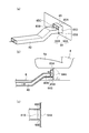
- FIG. 3 is a schematic configuration diagram of the vehicle air conditioning system according to the first embodiment.
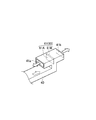
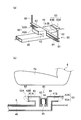
- FIG. 4 is a perspective view showing only the tip of the blowout duct according to the first embodiment.
- Fig.5 (a) is a perspective view which shows only the front-end
- FIG.5 (b) is a plane of the blowing duct which concerns on the modification 1 of 1st Embodiment.
- FIG. FIG. 6 is a perspective view showing only the tip of the outlet duct according to the second modification of the first embodiment.
- FIG. 7 is a schematic configuration diagram of a vehicle air conditioning system according to the second embodiment.
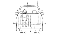
- FIG. 8 is a schematic front view showing the vehicle air conditioning system according to the second embodiment.
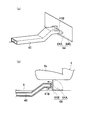
- Fig.9 (a) is a perspective view which shows the front-end
- FIG.9 (b) is a cross section showing the side which shows the front-end
- FIG. 10 (a), 10 (b), and 10 (c) are a perspective view, a cross-sectional view showing a side, and a cross-section showing a plan view, respectively, of the tip of a blowout duct according to Modification 1 of the third embodiment.
- FIG. 10 (a), 10 (b), and 10 (c) are a perspective view, a cross-sectional view showing a side, and a cross-section showing a plan view, respectively, of the tip of a
- FIG. 11 (a), 11 (b), and 11 (c) are a perspective view, a cross-sectional view showing a side, and a cross-section showing a plan view, respectively, of the tip of a blowout duct according to Modification 2 of the third embodiment.
- FIG. 12 (a), 12 (b), and 12 (c) are a perspective view, a cross-sectional view showing a side, and a cross-section showing a plan view, respectively, of the tip of a blowout duct according to Modification 3 of the third embodiment.
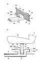
- FIG. FIG. 13 is a schematic side view showing the vehicle air conditioning system according to the fourth embodiment.
- FIG. 14 is a schematic configuration diagram of a vehicle air conditioning system according to the fourth embodiment.
- FIG. 15B are a perspective view and a cross-sectional view showing the side of the tip (contracted state of the expansion / contraction part) of the blowout duct according to the fourth embodiment, respectively.
- FIG. 16A and FIG. 16B are a perspective view and a cross-sectional view showing the side of the tip (extended state of the expansion / contraction part) of the blowout duct according to the fourth embodiment, respectively.
- FIG. 17 is a schematic side view showing a vehicle air conditioning system according to the background art.
- the vehicle air conditioning system 10 is provided in an instrument panel 3 provided in the foremost part of the passenger compartment 2 of the vehicle 1.
- the passenger compartment 2 two front seats 4 for a driver seat and a passenger seat and one long rear seat 5 (see FIG. 2) are provided.
- Each front seat 4 has a seat cushion 4a, a seat back 4b, and a headrest 4c.
- the rear seat 5 has a seat cushion 5a, a seat back 5b, and two headrests 5c.
- a vehicle air conditioning system 10 provided in such a vehicle 1 includes an air conditioner 20 that supplies desired conditioned air into the passenger compartment 2, and a front seat 4 (seats).
- the blower duct 40 having the blower outlet 41 for blowing the conditioned air into the passenger compartment 2 below the cushion 4a), the wind direction adjusting means 60 for adjusting the direction of the conditioned air blown from the blower outlet 41, and the air conditioner 20 are operated.
- An operation panel (not shown) and a control unit (not shown) for controlling each part and performing various calculations are provided.
- the air conditioner 20 has an air conditioning unit 21 arranged inside the instrument panel 3. As shown in FIG. 3, an air passage 22 is formed in the air conditioning unit 21. In the uppermost stream of the air passage 22, an outside air introduction port 23 for introducing outside air that is air outside the passenger compartment 2 and an inside air that is provided below the seat cushion 4 a and introduces inside air that is air inside the passenger compartment 2. An inlet 24 is provided. The outside air introduction port 23 and the inside air introduction port 24 are opened and closed by two intake doors 25a and 25b.
- a blower 26 is provided for sucking inside air and outside air into the air passage 22 by rotation of the fan.
- an evaporator 27 and a heater core 28, which are heat exchange units, are arranged in this order, and a mix door 29 is provided between the evaporator 27 and the heater core 28.
- the evaporator 27 is a cooling source for blowing air.
- the evaporator 27 is arranged so that all the air passing through the air passage 22 passes through, and cools the air.
- the heater core 28 is a heat source for blowing air.
- the heater core 28 is disposed in a substantially half region of the air passage 22 and heats the air.
- the mix door 29 adjusts the ratio of the airflow that flows through the heater core 28 and the airflow that bypasses the heater core 28. Air-conditioned air at a desired temperature is produced according to the ratio of the air volume sent.
- an air conditioning outlet 30 for blowing conditioned air into the passenger compartment 2 is provided downstream of the heater core 28.
- the air-conditioning outlet 30 emits conditioned air toward the upper body of each occupant of the front seat 4 (driver seat side and passenger seat side) and the defroster outlet 31 that blows air-conditioned air toward the windshield (not shown). Vent outlets 32a and 32b for blowing out, and foot outlets 33a and 33b) as foot outlets for blowing air-conditioned air toward the lower body of each occupant on the driver's seat and passenger seat side.
- the defroster outlet 31 is opened and closed by a differential door 34, the vent outlets 32a and 32b are opened and closed by a vent door 35, and the foot outlets 33a and 33b are opened and closed by a foot door 36.
- the blowout duct 40 extends from the downstream side of the heat exchange part (evaporator 27 and heater core 28) of the air passage 22 to the lower side of the front seat 4, and is opened and closed by the blowout duct door 37. Specifically, the blowout duct 40 passes through the lower side of the floor portion 6 (floor panel) from the air passage 22, bends at a substantially right angle below the front seat 4, passes through the floor portion 6, and moves forward of the vehicle 1. And it branches back and is provided in T shape seeing from the side.
- the air outlet 41 described above is provided at the tip of the air outlet duct 40.
- the air outlet 41 includes a front air outlet 41A that blows conditioned air to the front of the vehicle 1 below the front seat 4, and a rear air outlet 41B that blows conditioned air to the rear of the vehicle 1 below the front seat 4. Yes.
- a wind direction adjusting means 60 is provided between the front air outlet 41A and the rear air outlet 41B.
- the wind direction adjusting means 60 adjusts the direction in which the conditioned air blows out toward at least one of the foot side of the front seat 4 and the foot side of the rear seat 5.
- the wind direction adjusting means 60 is configured by one open / close door 61 as an open / close member that can open and close the front air outlet 41A and the rear air outlet 41B.
- the open / close door 61 is provided at a branch point of the front outlet 41A and the rear outlet 41B of the outlet duct 40.
- the open / close door 61 includes a door main body 61A and a rotation shaft 61B provided on the front seat 4 side and serving as a rotation center of the door main body 61A.
- Such an open / close door 61 adjusts the air volume of the conditioned air blown from the front outlet 41A and the rear outlet 41B according to the stop position together with the outlet duct door 37.
- an actuator or a manual is mentioned.
- An operation panel (not shown) can command various air conditioning states. On the operation panel, an overall air conditioning mode for air conditioning the entire interior of the passenger compartment 2 and a zone air conditioning mode for preferentially air conditioning the space of the front seat 4 in the passenger compartment 2 can be selected.
- a control unit controls the air conditioner 20 by a command from an operation panel (not shown), and various doors (intake doors 25a and 25b, a mix door 29, a differential door 34, a vent door 35, a foot door 36, The switching of the blowout duct door 37 and the open / close door 61) is controlled.
- the control unit performs control so as to blow conditioned air from the rear outlet 41B.
- the control unit stops the conditioned air blown from the rear outlet 41B, and from the front outlet 41A. Control to blow conditioned air. Specific switching contents will be described later.
- the vehicle air conditioning system 10 includes the overall air conditioning mode (so-called normal air conditioning mode) and the zone air conditioning mode.
- the overall air conditioning mode so-called normal air conditioning mode
- the zone air conditioning mode is demonstrated.
- the foot air outlets 33a and 33b are opened and the air outlet 41 (the front air outlet 41A and the rear air outlet 41B) is also opened, and the conditioned air is blown out from the opened air outlet. Therefore, the conditioned air blown out from the air conditioner 20 into the passenger compartment 2 flows to almost the entire area of the passenger compartment 2, and the entire interior of the passenger compartment 2 is air-conditioned.
- the open / close door 61 does not necessarily need to open the front outlet 41A and the rear outlet 41B.
- the open / close door 61 can have the front outlet 41A as a closed position and the rear outlet 41B as an open position. The amount of conditioned air blown out from the front outlet 41A and the rear outlet 41B is adjusted by the stop position of the open / close door 61.
- Zone air conditioning mode In the zone air-conditioning mode, the conditioned air at a desired temperature is blown into the passenger compartment 2 from the foot outlets 33a and 33b and the front outlet 41A, as in the overall air-conditioning mode. That is, the foot outlets 33a and 33b are opened, the rear outlet 41B is closed and the front outlet 41A is opened, and the conditioned air is blown out from the opened outlet. At this time, the conditioned air blown out from the front outlet 41A to the front of the vehicle 1 is larger than the conditioned air blown out from the foot outlets 33a and 33b.
- the conditioned air blown into the passenger compartment 2 intensively passes around the front seat 4 (mainly the height position of the lower body of the occupant) and is connected to the inside air inlet 24 (step suction inlet 38 ( 2), the air is sucked by the suction force of the blower 26 and returned to the air conditioning unit 21.
- the conditioned air can be prevented from flowing into the space of the rear seat 5, and a zone air-conditioning region is formed in the front seat 4 in the passenger compartment 2.
- the air that the air conditioning apparatus 20 has sucked into the air passage 22 by the blower 26 is converted into desired conditioned air by the evaporator 27 and the heater core 28 that are heat exchange units. Convert. And the blower outlet 41 (front blower outlet 41A and rear blower outlet 41B) of the blower duct 40 extended from the downstream side of the evaporator 27 and heater core 28 which are the heat exchange parts arrange
- the conditioned air can be blown forward of the vehicle 1 when it is desired to air-condition the front seat 4,
- conditioned air can be blown out to the rear of the vehicle 1. That is, the conditioned air can be blown from either the front air outlet 41A or the rear air outlet 41B or both. For this reason, even if it does not extend the blowing duct 40 to the rear seat 5 side, the rear seat 5 can be air-conditioned. Therefore, the air conditioning of the front seat 4 side and the rear seat 5 side can be efficiently performed without securing the installation space for the blowout duct 40 on the rear seat 5 side.
- the blower outlet 41 of the blower duct 40 is comprised by 41 A of front blower outlets, and the rear blower outlet 41B, and it blows off air-conditioning wind only from 41 A of front blower outlets, or only from the rear blower outlet 41B.
- the conditioned air can be blown out from both the front outlet 41A and the rear outlet 41B.
- the opening / closing door 61 is provided in each of the front air outlet 41A and the rear air outlet 41B by adjusting the air volume of the conditioned air blown from the front air outlet 41A and the rear air outlet 41B depending on the stop position of the door 61. Compared to the case, only one open / close door 61 is required, and conditioned air can be blown out from at least one of the front outlet 41A and the rear outlet 41B.
- the air-conditioning air blown from the front air outlet 41 ⁇ / b> A to the front of the vehicle 1 blows out from the foot air outlets 33 a and 33 b that are foot air outlets that blow air-conditioned air from the front of the vehicle 1 to the lower side of the front seat 4.
- the foot air outlets 33 a and 33 b are foot air outlets that blow air-conditioned air from the front of the vehicle 1 to the lower side of the front seat 4.
- FIGS. 5A and 5B are diagrams showing only the tip of the blowout duct 40 according to the first modification.
- the blowout duct 40 is bent at a substantially right angle in the width direction of the vehicle 1, and is further bent at a substantially right angle in front of the vehicle 1. That is, the blowing duct 40 is provided in a U shape in plan view.
- the blowout duct 40 is bent and a front blowout port 41A is provided at the front end, and a rear blowout port 41B is provided on the rear side before the blowout duct 40 is bent.
- An opening / closing door 61 as a wind direction adjusting means 60 is provided at the position of the rear outlet 41B.
- the space between the front seat 4 side and the rear seat 5 side is ensured without securing the installation space for the blowing duct 40 on the rear seat 5 side. Air conditioning can be performed efficiently.
- the opening / closing door 61 is provided in each of the front air outlet 41A and the rear air outlet 41B by adjusting the air volume of the conditioned air blown from the front air outlet 41A and the rear air outlet 41B depending on the stop position of the door 61. Compared to the case, only one open / close door 61 is required, and conditioned air can be blown out from at least one of the front outlet 41A and the rear outlet 41B.
- FIG. 6 is a perspective view showing only the tip of the blowing duct 40 according to the second modification.
- the blowing duct 40 includes a main body duct 40A and a cylindrical tip member 40B that is provided so as to be rotatable with respect to the main body duct 40A and has one outlet 41.
- the distal end member 40B extends upward from the upper end of the distal end of the main body duct 40A and is bent at a substantially right angle. That is, the tip member 40B is provided in an L shape in side view.
- the wind direction adjustment means 60 has the switching means (for example, actuator) which is not shown in figure which switches the direction of one blower outlet 41 to the front or back of the vehicle 1 by rotating the front-end
- the space between the front seat 4 side and the rear seat 5 side is ensured without securing the installation space for the blowing duct 40 on the rear seat 5 side. Air conditioning can be performed efficiently.
- the wind direction adjusting means 60 switches the direction of one air outlet 41 to the front or rear of the vehicle 1 by rotating the tip member 40B, and to the front seat 4 side and the rear seat 5 side depending on the stop position.
- the ratio of the flowing air volume can be adjusted, and air conditioning between the front seat 4 side and the rear seat 5 side can be performed efficiently.
- FIG.7 and FIG.8 is a figure which shows the air conditioning system 10 for vehicles which concerns on 2nd Embodiment.
- symbol is attached
- the vehicle air conditioning system 10 according to the second embodiment differs from the vehicle air conditioning system 10 according to the first embodiment in the configuration of the wind direction adjusting means 60.
- the wind direction adjusting means 60 is configured by a front opening / closing door 62 that opens and closes the front outlet 41A and a rear opening / closing door 63 as a partitioning means that opens and closes the rear outlet 41B. ing.
- the front opening / closing door 62 has a door main body 62A and a rotation shaft 62B provided on the front seat 4 side and serving as a rotation center of the door main body 62A.
- the front opening / closing door 62 can open and close the front outlet 41 ⁇ / b> A by conditioned air (internal pressure) passing through the outlet duct 40.
- conditioned air internal pressure
- the front opening / closing door 62 closes the front outlet 41A.
- the rear opening / closing door 63 as a partition means does not partition the partition position (solid line in FIG. 7) that partitions the lower space of the front seat 4 into the front side and the rear side of the vehicle 1 and the front side and the rear side of the vehicle 1. It rotates between the open positions (two-dot chain lines in FIG. 7).
- the rear opening / closing door 63 has a door main body 63A and a rotation shaft 63B provided on the floor 6 side and serving as a rotation center of the door main body 63A.
- the door main body 63A has a width wider than the width of the seat cushion 4a in order to partition the lower space of the seat cushion 4a into the front side and the rear side of the vehicle 1.
- an actuator or a manual is mentioned.
- the rear opening / closing door 63 In the overall air conditioning mode, as shown by a two-dot chain line in FIG. 7, the rear opening / closing door 63 is in the open position to open the rear outlet 41B, and the conditioned air flows from the rear outlet 41B into the passenger compartment 2 (of the vehicle 1). Be blown out backward).
- the front opening / closing door 62 Since the internal pressure of the conditioned air in the blowing duct 40 does not increase, the front opening / closing door 62 is in the closed position and closes the front outlet 41A. Therefore, the conditioned air blown out from the air conditioner 20 into the passenger compartment 2 flows to almost the entire area of the passenger compartment 2, and the entire interior of the passenger compartment 2 is air-conditioned.
- the rear opening / closing door 63 is in the closed position and closes the rear outlet 41B.
- the front air outlet 41A is opened by the conditioned air (internal pressure) passing through the air outlet duct 40, the front air outlet 41A is opened, and the air conditioned air passes through the front air outlet 41A in the vehicle compartment 2 (front of the vehicle 1). Is blown out. Therefore, the conditioned air blown into the passenger compartment 2 intensively passes around the front seat 4 (mainly the height position of the lower body of the occupant) and from the foot suction port 38 connected to the inside air introduction port 24.
- the air is sucked by the suction force of the blower 26 and returned to the air conditioning unit 21.
- the conditioned air can be prevented from flowing into the space of the rear seat 5, and a zone air-conditioning region is formed in the front seat 4 in the passenger compartment 2.
- the front seat 4 side and the rear seat 5 side can be provided without securing the installation space for the outlet duct 40 on the rear seat 5 side. Air conditioning can be performed efficiently.
- the wind direction adjusting means 60 is constituted by the front opening / closing door 62 which is an opening / closing member capable of opening / closing the front outlet 41A by the conditioned air passing through the blowing duct 40, thereby rotating the front opening / closing door 62.
- a mechanism such as an actuator to be moved becomes unnecessary.
- the rear opening / closing door 63 as a partitioning means partitions the lower space of the front seat 4 into the front side and the rear side of the vehicle 1 so as to blow out air from the foot outlets 33a and 33b in the zone air conditioning mode.
- the wind can be prevented from flowing to the rear seat 5 side.
- the door main body 63A of the rear opening / closing door 63 has been described as having a width wider than the width of the seat cushion 4a, but is not limited to this, and is divided into a front side and a rear side of the vehicle 1. If it is not necessary, the size may be a size capable of opening and closing the rear outlet 41 ⁇ / b> B, such as the front opening / closing door 62.
- FIG.9 (a) is a perspective view which shows the front-end
- FIG.9 (b) represents the side surface which shows the front-end
- symbol is attached
- the blowout duct 40 according to the third embodiment differs from the vehicle air conditioning system 10 according to the first and second embodiments in the configuration of the tip of the blowout duct 40 and the configuration of the open / close door.
- the blowout duct 40 includes only a rear outlet 41 ⁇ / b> B that blows conditioned air behind the vehicle 1.
- the wind direction adjusting means is a partition means that moves between a partition position that partitions the lower space of the front seat 4 into the front side and the rear side of the vehicle 1 and an open position that does not partition the front side and the rear side of the vehicle 1.
- the partition door 64 is configured.
- the partition door 64 is provided behind the vehicle outlet 1 from the rear outlet 41B.
- the partition door 64 has a door body 64A and a rotation shaft 64B provided on the floor 6 and serving as a rotation center of the door body 64A.
- the door main body 64A has a width wider than the width of the seat cushion 4a in order to partition the lower space of the seat cushion 4a into the front side and the rear side of the vehicle 1.
- an actuator or a manual is mentioned.
- the partition door 64 as the partitioning unit is in the open position, the rear outlet 41B is opened toward the rear seat 5, and the conditioned air is generated.
- the air is blown into the passenger compartment 2 (rear of the vehicle 1) from the rear outlet 41B. Therefore, the conditioned air blown out from the air conditioner 20 into the passenger compartment 2 flows to almost the entire area of the passenger compartment 2, and the entire interior of the passenger compartment 2 is air-conditioned.
- the partition door 64 as the partition means is the partition position.
- the partition door 64 since the partition door 64 is located at a position separated from the rear outlet 41 ⁇ / b> B, the air is blown forward of the vehicle 1 by the conditioned air blowing against the partition door 64. Therefore, the conditioned air blown into the passenger compartment 2 intensively passes around the front seat 4 (mainly the height position of the lower body of the occupant) and from the foot suction port 38 connected to the inside air introduction port 24. The air is sucked by the suction force of the blower 26 and returned to the air conditioning unit 21. As a result, the conditioned air can be prevented from flowing into the space of the rear seat 5, and a zone air-conditioning region is formed in the front seat 4 in the passenger compartment 2.
- the front seat 4 side and the rear seat can be secured without securing the installation space for the blowing duct 40 on the rear seat 5 side. Air conditioning with the 5 side can be performed efficiently.
- the partition door 64 partitions the lower space of the front seat 4 into the front side and the rear side of the vehicle 1. It is possible to prevent the conditioned air blown from the foot outlets 33a and 33b and the rear outlet 41B from flowing to the rear seat 5 side.
- FIGS. 10A, 10 ⁇ / b> B, and 10 ⁇ / b> C are diagrams showing the tip of the blowing duct 40 according to the first modification.
- the partition door 64 includes a door body 64A and a rotation shaft 64B provided on the floor 6 and serving as a rotation center of the door body 64A.
- the door main body 64 ⁇ / b> A has a guide portion 65 that guides the conditioned air to the front of the vehicle 1 at the partition position of the partition door 64.
- the guide portion 65 is provided at a position corresponding to the rear outlet 41 ⁇ / b> B at the partition position of the partition door 64.
- the guide part 65 is formed larger than the rear outlet 41B.
- the guide portion 65 includes an upper wall 65A, a bottom wall 65B, and a pair of side walls 65C and 65D.
- the upper wall 65 ⁇ / b> A, the bottom wall 65 ⁇ / b> B, and the side walls 65 ⁇ / b> C and 65 ⁇ / b> D are provided apart from the blowing duct 40. That is, a gap through which conditioned air can pass is provided between each of the upper wall 65A, the bottom wall 65B, the side walls 65C and 65D, and the blowing duct 40.
- Such a partition door 64 becomes a partition position in the zone air-conditioning mode, and air is blown to the front of the vehicle 1 through the gap when the conditioned air blows against the partition door 64.
- description here is abbreviate
- the partition door 64 partitions the lower space of the front seat 4 into the front side and the rear side of the vehicle 1, thereby enabling the zone air conditioning mode. At this time, the conditioned air blown from the foot outlets 33a and 33b and the rear outlet 41B can be prevented from flowing to the rear seat 5 side.
- the guide portion 65 in the door main body 64A the conditioned air blown from the rear outlet 41B in the zone air conditioning mode is easily guided to the front of the vehicle 1 without being diffused to the surroundings.
- FIGS. 11A, 11 ⁇ / b> B, and 11 ⁇ / b> C are diagrams illustrating the tip of the blowout duct 40 according to the second modification.
- the door body 64A of the partition door 64 emits conditioned air at the partition position of the partition door 64 in the same manner as in the first modification described above.
- a guide portion 65 for guiding the vehicle 1 forward is provided.
- the upper wall 65A of the guide portion 65 is provided apart from the blowout duct 40, and the bottom wall 65B and the side walls 65C and 65D are in contact with the leading edge of the blowout duct 40 at the partitioning position of the partition door 64. It is provided in the state. That is, a gap through which the conditioned air can pass is provided between the upper wall 65A and the blowout duct 40.
- Such a partition door 64 becomes a partition position in the zone air-conditioning mode, and air is blown to the front of the vehicle 1 through the gap when the conditioned air blows against the partition door 64.
- description here is abbreviate
- the partition door 64 partitions the lower space of the front seat 4 into the front side and the rear side of the vehicle 1 in the zone air conditioning mode, as in the operation and effect of the modified example 1 described above.
- the conditioned air blown from the foot outlets 33a, 33b and the rear outlet 41B can be prevented from flowing to the rear seat 5 side.
- the guide portion 65 in the door main body 64A the conditioned air blown from the rear outlet 41B in the zone air conditioning mode is easily guided to the front of the vehicle 1 without being diffused to the surroundings.
- FIGS. 12A, 12 ⁇ / b> B, and 12 ⁇ / b> C are views showing the tip of the blowing duct 40 according to the third modification.
- the rotation shaft 64 ⁇ / b> B of the partition door 64 is fixed not to the floor 6 but to the rear outlet 41 ⁇ / b> B of the outlet duct 40. That is, the rotation shaft 64B connects the front end edge of the rear outlet 41B and the front end of the bottom wall 65B.
- the configuration of the door main body 64A of the partition door 64 is the same as that of the above-described modification example 2, and thus the description thereof is omitted here.
- the partition door 64 partitions the lower space of the front seat 4 into the front side and the rear side of the vehicle 1, thereby enabling zone air conditioning. It is possible to prevent the conditioned air blown from the foot outlets 33a and 33b and the rear outlet 41B from flowing to the rear seat 5 side in the mode.
- the guide portion 65 in the door main body 64A by providing the guide portion 65 in the door main body 64A, the conditioned air blown from the rear outlet 41B in the zone air conditioning mode is easily guided to the front of the vehicle 1 without being diffused to the surroundings.
- the rotating shaft 64B of the partition door 64 is fixed to the rear outlet 41B of the outlet duct 40, so that the outlet duct 40 and the partition door 64 are set as one set without being fixed on the floor portion 6. It can be attached below the front seat 4 and contributes to simplification of the attachment process.
- FIGS. 13 to 16 (a) and 16 (b) show the vehicle air conditioning system 10 according to the fourth embodiment.
- the same parts as those in the vehicle air conditioning system 10 according to the first to third embodiments described above are denoted by the same reference numerals, and different parts will be mainly described.
- the blowout duct 40 according to the fourth embodiment is different from the vehicle air conditioning system 10 according to the first to third embodiments in the configuration of the tip of the blowout duct 40 and the configuration of the open / close door.
- the vehicle air conditioning system 10 includes, in addition to the air conditioning apparatus 20, the blowout duct 40, and the wind direction adjusting means described above, There is further provided expansion / contraction partition means 80 that communicates with the blowing duct 40 and is provided below the front seat 4.
- the blowout duct 40 is branched below the front seat 4 into a front duct 43 in which a front blowout port 41A is formed and a rear duct 44 in which a rear blowout port 41B is formed.
- the wind direction adjusting means includes a front opening / closing door 62 for opening / closing the front outlet 41A and a rear opening / closing door 63 for opening / closing the rear outlet 41B.
- the front opening / closing door 62 has a door main body 62A and a rotation shaft 62B provided on the front seat 4 side and serving as a rotation center of the door main body 62A.
- the rear opening / closing door 63 has a door main body 63A and a rotation shaft 63B provided on the front seat 4 side and serving as a rotation center of the door main body 63A.
- the rear opening / closing door 63 is formed in the same size as the front opening / closing door 62.
- the telescopic partitioning means 80 is provided between the front duct 43 and the rear duct 44 of the blowing duct 40 and communicates with the blowing duct 40 below the front seat 4.
- the expansion / contraction partitioning means 80 can partition the lower space of the front seat 4 into the front side and the rear side of the vehicle 1 by expanding and contracting in the vertical direction by the conditioned air (internal pressure) passing through the blowing duct 40. .
- the expansion / contraction partition means 80 has a lower plate portion 81 fixed to the floor portion 6.
- a bar-shaped guide portion 82 provided at both ends of the lower plate portion 81 and extending in the vertical direction in the lower space of the front seat 4, and an upper plate portion 83 movable in the vertical direction along the guide portion 82,
- An expansion / contraction portion 84 made of a bellows-like non-breathable material (for example, synthetic resin or synthetic fiber) that is fixed to the lower plate portion 81 and the upper plate portion 83 and that can expand and contract in the vertical direction is provided.
- the front opening / closing door 62 is closed and the front outlet 41A is closed, and the rear opening / closing door 63 is opened and rearward.
- the blower outlet 41B opens.
- the conditioned air is blown out into the passenger compartment 2 (rear of the vehicle 1) from the rear outlet 41B.
- the expansion / contraction part 84 of the expansion / contraction partition means 80 is in a contracted state without increasing the internal pressure of the conditioned air in the blowing duct 40. Therefore, the conditioned air blown out from the air conditioner 20 into the passenger compartment 2 flows to almost the entire area of the passenger compartment 2, and the entire interior of the passenger compartment 2 is air-conditioned.
- the rear opening / closing door 63 is closed and the rear outlet 41B is closed.
- the blowout duct door 37 since the blowout duct door 37 is in the open position, the conditioned air directed toward the rear outlet 41B loses its destination, the internal pressure of the conditioned air in the blowout duct 40 increases, and the conditioned air expands and contracts the telescopic partition means 80. The air is blown into the portion 84.
- the expansion / contraction part 84 of the expansion / contraction partition means 80 is in an extended state, and the lower space of the front seat 4 is partitioned into the front side and the rear side of the vehicle 1.
- the front air outlet 41A is opened toward the front side of the vehicle 1, so that the conditioned air is blown out from the front air outlet 41A to the front of the vehicle 1. Therefore, the conditioned air blown into the passenger compartment 2 intensively passes around the front seat 4 (mainly the height position of the lower body of the occupant) and from the foot suction port 38 connected to the inside air introduction port 24. The air is sucked by the suction force of the blower 26 and returned to the air conditioning unit 21. As a result, the conditioned air can be prevented from flowing into the space of the rear seat 5, and a zone air-conditioning region is formed in the front seat 4 in the passenger compartment 2.
- the expansion partition means 80 expands and contracts in the vertical direction, so that the lower space of the front seat 4 is moved to the front side and the rear side of the vehicle 1.
- partitioning in the air conditioning mode it is possible to prevent the conditioned air blown from the foot outlets 33a and 33b and the rear outlet 41B from flowing to the rear seat 5 side in the zone air conditioning mode.
- the expansion / contraction partitioning means 80 described above expands and contracts up and down by the internal pressure of the conditioned air in the blowout duct 40, a mechanism such as an actuator becomes unnecessary.
- the embodiment of the present invention can be modified as follows.
- the vehicle air conditioning system 10 is not limited to that described in each embodiment, and the items described in each embodiment are merely examples, and various configurations described in each embodiment. May be combined.
- vehicle air conditioning system 10 has been described by taking the case of heating in the passenger compartment 2 as an example.
- the present invention is not limited to this, and is not limited to this.
- the present invention can also be applied to the bi-level method.
- blowout duct 40, the wind direction adjusting means, and the expansion / contraction partitioning means 80 have been described as being provided on the driver seat side and the passenger seat side, but the present invention is not limited thereto, and at least one of them (for example, driving) It may be provided on the seat side only). It may be controlled to drive only one of the driver seat side and the passenger seat side.
- blowout duct 40 and the wind direction adjusting means are not necessarily provided in the driver seat or the passenger seat, and may be provided, for example, between the driver seat and the passenger seat.
- the blowout duct 40 may be configured by a rear duct that supplies conditioned air to the foot side of the rear seat 5.
- a foot blower outlet It may be substantially the same as or slightly less than the conditioned air blown from 33a, 33b.
- wind direction adjusting means has been described as being constituted by a rotary door, it is not limited thereto, and for example, it may be constituted by a sliding door.
- the air direction adjusting means adjusts the direction of the conditioned air blown out from the air outlet of the blowout duct extending from the air passage to the lower part of the front seat, so that the air conditioning that prioritizes the front seat is performed.
- the wind can be blown forward of the vehicle, while the conditioned air can be blown rearward of the vehicle when it is desired to air-condition the rear seat. For this reason, it is possible to air-condition the rear seat without extending the outlet duct to the rear seat side. Therefore, it is possible to efficiently perform air conditioning on the front seat side and the rear seat side without securing an installation space for the blowout duct on the rear seat side.
- Air conditioning system for vehicles 20 Air conditioning apparatus 22 Blower path 26 Blower 27 Evaporator (heat exchange part) 28 Heater core (heat exchanger) 30 Air outlet 33a, 33b Foot outlet (foot outlet) 40 air outlet duct 40A main body duct 40B tip member 41 air outlet 41A front air outlet 41B rear air outlet 60 air direction adjusting means 61 opening / closing door (opening / closing member) 62 Front open / close door 63 Rear door (opening / closing member) 64 Partition door (partitioning means) 65 Guide part 80 Telescopic partitioning means
Landscapes
- Engineering & Computer Science (AREA)
- Physics & Mathematics (AREA)
- Thermal Sciences (AREA)
- Mechanical Engineering (AREA)
- Power Engineering (AREA)
- Air-Conditioning For Vehicles (AREA)
Abstract
Le système de conditionnement d'air pour véhicule (10) de l'invention est équipé : d'un dispositif de conditionnement d'air (20) qui décharge à l'intérieur d'un espace intérieur de véhicule (2), un air aspiré à l'intérieur d'un trajet de ventilation (22) à l'aide d'un appareil de ventilation (26), et le convertit en vent pour conditionnement d'air tel que souhaité à l'aide d'un évaporateur (27) ainsi que d'un radiateur de chauffage (28) ; d'un conduit de décharge (40) qui se prolonge depuis un côté aval de l'évaporateur (27) et du radiateur de chauffage (28) du trajet de ventilation (22) jusqu'en-dessous de sièges avant (4), et qui possède un orifice de décharge (41) déchargeant le vent pour conditionnement d'air à l'intérieur de l'espace intérieur de véhicule (2) sous les sièges avant (4) ; et d'un moyen d'ajustement de direction du vent (60) qui ajuste la direction du vent pour conditionnement d'air déchargé depuis ledit orifice de décharge (41).
Applications Claiming Priority (2)
| Application Number | Priority Date | Filing Date | Title |
|---|---|---|---|
| JP2013-072249 | 2013-03-29 | ||
| JP2013072249A JP2014196026A (ja) | 2013-03-29 | 2013-03-29 | 車両用空気調和システム |
Publications (1)
| Publication Number | Publication Date |
|---|---|
| WO2014155805A1 true WO2014155805A1 (fr) | 2014-10-02 |
Family
ID=51622842
Family Applications (1)
| Application Number | Title | Priority Date | Filing Date |
|---|---|---|---|
| PCT/JP2013/079748 Ceased WO2014155805A1 (fr) | 2013-03-29 | 2013-11-01 | Système de conditionnement d'air pour véhicule |
Country Status (2)
| Country | Link |
|---|---|
| JP (1) | JP2014196026A (fr) |
| WO (1) | WO2014155805A1 (fr) |
Cited By (4)
| Publication number | Priority date | Publication date | Assignee | Title |
|---|---|---|---|---|
| CN112088101A (zh) * | 2018-05-07 | 2020-12-15 | 株式会社电装 | 吹出装置 |
| CN115892239A (zh) * | 2021-09-30 | 2023-04-04 | 马自达汽车株式会社 | 车体构造 |
| WO2023112631A1 (fr) * | 2021-12-16 | 2023-06-22 | サンデン株式会社 | Dispositif de climatisation de véhicule |
| US12496869B2 (en) | 2021-09-30 | 2025-12-16 | Mazda Motor Corporation | Vehicle-body structure with air conditioner |
Families Citing this family (1)
| Publication number | Priority date | Publication date | Assignee | Title |
|---|---|---|---|---|
| JP6942106B2 (ja) * | 2018-09-25 | 2021-09-29 | 日立建機株式会社 | 作業機械の運転室及び作業機械 |
Citations (7)
| Publication number | Priority date | Publication date | Assignee | Title |
|---|---|---|---|---|
| JPS56174312U (fr) * | 1980-05-27 | 1981-12-23 | ||
| JPS5732506U (fr) * | 1980-07-31 | 1982-02-20 | ||
| JPS6130520U (ja) * | 1984-07-30 | 1986-02-24 | 河西工業株式会社 | エアダクト付サンバイザ |
| JPS61200713U (fr) * | 1985-06-06 | 1986-12-16 | ||
| JPS645814U (fr) * | 1987-06-30 | 1989-01-13 | ||
| WO2004085181A1 (fr) * | 2003-03-25 | 2004-10-07 | Jae Soo Ryu | Appareil destine a regler la direction du vent dans un systeme de chauffage et de refroidissement de vehicule |
| JP2010269706A (ja) * | 2009-05-21 | 2010-12-02 | Toyota Boshoku Corp | 車両天井構造 |
-
2013
- 2013-03-29 JP JP2013072249A patent/JP2014196026A/ja active Pending
- 2013-11-01 WO PCT/JP2013/079748 patent/WO2014155805A1/fr not_active Ceased
Patent Citations (7)
| Publication number | Priority date | Publication date | Assignee | Title |
|---|---|---|---|---|
| JPS56174312U (fr) * | 1980-05-27 | 1981-12-23 | ||
| JPS5732506U (fr) * | 1980-07-31 | 1982-02-20 | ||
| JPS6130520U (ja) * | 1984-07-30 | 1986-02-24 | 河西工業株式会社 | エアダクト付サンバイザ |
| JPS61200713U (fr) * | 1985-06-06 | 1986-12-16 | ||
| JPS645814U (fr) * | 1987-06-30 | 1989-01-13 | ||
| WO2004085181A1 (fr) * | 2003-03-25 | 2004-10-07 | Jae Soo Ryu | Appareil destine a regler la direction du vent dans un systeme de chauffage et de refroidissement de vehicule |
| JP2010269706A (ja) * | 2009-05-21 | 2010-12-02 | Toyota Boshoku Corp | 車両天井構造 |
Cited By (6)
| Publication number | Priority date | Publication date | Assignee | Title |
|---|---|---|---|---|
| CN112088101A (zh) * | 2018-05-07 | 2020-12-15 | 株式会社电装 | 吹出装置 |
| CN112088101B (zh) * | 2018-05-07 | 2023-05-02 | 株式会社电装 | 吹出装置 |
| CN115892239A (zh) * | 2021-09-30 | 2023-04-04 | 马自达汽车株式会社 | 车体构造 |
| CN115892239B (zh) * | 2021-09-30 | 2025-11-28 | 马自达汽车株式会社 | 车体构造 |
| US12496869B2 (en) | 2021-09-30 | 2025-12-16 | Mazda Motor Corporation | Vehicle-body structure with air conditioner |
| WO2023112631A1 (fr) * | 2021-12-16 | 2023-06-22 | サンデン株式会社 | Dispositif de climatisation de véhicule |
Also Published As
| Publication number | Publication date |
|---|---|
| JP2014196026A (ja) | 2014-10-16 |
Similar Documents
| Publication | Publication Date | Title |
|---|---|---|
| JP5706923B2 (ja) | 車両用空気調和装置 | |
| JP6318931B2 (ja) | 空気吹出装置 | |
| JP2015164837A (ja) | 車両用空気調和装置 | |
| JP2009202687A (ja) | 車両用空調装置 | |
| WO2014155805A1 (fr) | Système de conditionnement d'air pour véhicule | |
| JP2014180985A (ja) | 車両用空気調和システム | |
| JP2014141236A (ja) | 車両用空気調和システム | |
| EP2500192A1 (fr) | Appareil de climatisation d'air pour véhicule | |
| EP2650153A1 (fr) | Système de climatisation pour véhicule | |
| WO2018016196A1 (fr) | Appareil de climatisation de véhicule | |
| JP2014196028A (ja) | 車両用空気調和システム | |
| JP4364581B2 (ja) | 乗用車の空気案内構造 | |
| JP2008183959A (ja) | 車両用空調装置 | |
| WO2014103610A1 (fr) | Système de conditionnement d'air pour véhicule | |
| JP7231460B2 (ja) | 空気吹出装置 | |
| JP2006240539A (ja) | 車両用空調装置 | |
| JP2013132925A (ja) | 車両用空気調和システムの吸込口装置 | |
| JP2005153826A (ja) | 車両用空調装置 | |
| JP2012121482A (ja) | 車両用空気調和システム | |
| JP4333306B2 (ja) | 車両用空調装置 | |
| JP6481631B2 (ja) | 車両用空気吹き出し装置 | |
| JP2013129370A (ja) | 車両用空気調和システムの吸込口装置 | |
| JP2012245804A (ja) | 車両用空気調和システム | |
| JP4333307B2 (ja) | 車両用空調装置 | |
| JP4812509B2 (ja) | 自動車用空気調和装置 |
Legal Events
| Date | Code | Title | Description |
|---|---|---|---|
| 121 | Ep: the epo has been informed by wipo that ep was designated in this application |
Ref document number: 13879860 Country of ref document: EP Kind code of ref document: A1 |
|
| NENP | Non-entry into the national phase |
Ref country code: DE |
|
| 122 | Ep: pct application non-entry in european phase |
Ref document number: 13879860 Country of ref document: EP Kind code of ref document: A1 |