WO2014155996A1 - Dispositif de production d'hydrogène, système de pile à combustible pourvu de ce dernier, procédé de mise en œuvre du dispositif de production d'hydrogène, et procédé de mise en œuvre du système de pile à combustible - Google Patents
Dispositif de production d'hydrogène, système de pile à combustible pourvu de ce dernier, procédé de mise en œuvre du dispositif de production d'hydrogène, et procédé de mise en œuvre du système de pile à combustible Download PDFInfo
- Publication number
- WO2014155996A1 WO2014155996A1 PCT/JP2014/001291 JP2014001291W WO2014155996A1 WO 2014155996 A1 WO2014155996 A1 WO 2014155996A1 JP 2014001291 W JP2014001291 W JP 2014001291W WO 2014155996 A1 WO2014155996 A1 WO 2014155996A1
- Authority
- WO
- WIPO (PCT)
- Prior art keywords
- hydrogen generator
- combustor
- temperature
- fuel cell
- combustion
- Prior art date
- Legal status (The legal status is an assumption and is not a legal conclusion. Google has not performed a legal analysis and makes no representation as to the accuracy of the status listed.)
- Ceased
Links
Images



Classifications
-
- H—ELECTRICITY
- H01—ELECTRIC ELEMENTS
- H01M—PROCESSES OR MEANS, e.g. BATTERIES, FOR THE DIRECT CONVERSION OF CHEMICAL ENERGY INTO ELECTRICAL ENERGY
- H01M8/00—Fuel cells; Manufacture thereof
- H01M8/06—Combination of fuel cells with means for production of reactants or for treatment of residues
- H01M8/0606—Combination of fuel cells with means for production of reactants or for treatment of residues with means for production of gaseous reactants
- H01M8/0612—Combination of fuel cells with means for production of reactants or for treatment of residues with means for production of gaseous reactants from carbon-containing material
- H01M8/0625—Combination of fuel cells with means for production of reactants or for treatment of residues with means for production of gaseous reactants from carbon-containing material in a modular combined reactor/fuel cell structure
-
- C—CHEMISTRY; METALLURGY
- C01—INORGANIC CHEMISTRY
- C01B—NON-METALLIC ELEMENTS; COMPOUNDS THEREOF; METALLOIDS OR COMPOUNDS THEREOF NOT COVERED BY SUBCLASS C01C
- C01B3/00—Hydrogen; Gaseous mixtures containing hydrogen; Separation of hydrogen from mixtures containing it; Purification of hydrogen; Reversible storage of hydrogen
- C01B3/02—Production of hydrogen; Production of gaseous mixtures containing hydrogen
- C01B3/32—Production of hydrogen; Production of gaseous mixtures containing hydrogen by reaction of gaseous or liquid organic compounds with gasifying agents, e.g. water, carbon dioxide or air
- C01B3/34—Production of hydrogen; Production of gaseous mixtures containing hydrogen by reaction of gaseous or liquid organic compounds with gasifying agents, e.g. water, carbon dioxide or air by reaction of hydrocarbons with gasifying agents
- C01B3/38—Production of hydrogen; Production of gaseous mixtures containing hydrogen by reaction of gaseous or liquid organic compounds with gasifying agents, e.g. water, carbon dioxide or air by reaction of hydrocarbons with gasifying agents using catalysts
- C01B3/40—Production of hydrogen; Production of gaseous mixtures containing hydrogen by reaction of gaseous or liquid organic compounds with gasifying agents, e.g. water, carbon dioxide or air by reaction of hydrocarbons with gasifying agents using catalysts characterised by the catalyst
-
- H—ELECTRICITY
- H01—ELECTRIC ELEMENTS
- H01M—PROCESSES OR MEANS, e.g. BATTERIES, FOR THE DIRECT CONVERSION OF CHEMICAL ENERGY INTO ELECTRICAL ENERGY
- H01M8/00—Fuel cells; Manufacture thereof
- H01M8/06—Combination of fuel cells with means for production of reactants or for treatment of residues
- H01M8/0606—Combination of fuel cells with means for production of reactants or for treatment of residues with means for production of gaseous reactants
- H01M8/0612—Combination of fuel cells with means for production of reactants or for treatment of residues with means for production of gaseous reactants from carbon-containing material
- H01M8/0618—Reforming processes, e.g. autothermal, partial oxidation or steam reforming
-
- C—CHEMISTRY; METALLURGY
- C01—INORGANIC CHEMISTRY
- C01B—NON-METALLIC ELEMENTS; COMPOUNDS THEREOF; METALLOIDS OR COMPOUNDS THEREOF NOT COVERED BY SUBCLASS C01C
- C01B2203/00—Integrated processes for the production of hydrogen or synthesis gas
- C01B2203/02—Processes for making hydrogen or synthesis gas
- C01B2203/0205—Processes for making hydrogen or synthesis gas containing a reforming step
- C01B2203/0227—Processes for making hydrogen or synthesis gas containing a reforming step containing a catalytic reforming step
- C01B2203/0233—Processes for making hydrogen or synthesis gas containing a reforming step containing a catalytic reforming step the reforming step being a steam reforming step
-
- C—CHEMISTRY; METALLURGY
- C01—INORGANIC CHEMISTRY
- C01B—NON-METALLIC ELEMENTS; COMPOUNDS THEREOF; METALLOIDS OR COMPOUNDS THEREOF NOT COVERED BY SUBCLASS C01C
- C01B2203/00—Integrated processes for the production of hydrogen or synthesis gas
- C01B2203/02—Processes for making hydrogen or synthesis gas
- C01B2203/0205—Processes for making hydrogen or synthesis gas containing a reforming step
- C01B2203/0227—Processes for making hydrogen or synthesis gas containing a reforming step containing a catalytic reforming step
- C01B2203/0244—Processes for making hydrogen or synthesis gas containing a reforming step containing a catalytic reforming step the reforming step being an autothermal reforming step, e.g. secondary reforming processes
-
- C—CHEMISTRY; METALLURGY
- C01—INORGANIC CHEMISTRY
- C01B—NON-METALLIC ELEMENTS; COMPOUNDS THEREOF; METALLOIDS OR COMPOUNDS THEREOF NOT COVERED BY SUBCLASS C01C
- C01B2203/00—Integrated processes for the production of hydrogen or synthesis gas
- C01B2203/02—Processes for making hydrogen or synthesis gas
- C01B2203/025—Processes for making hydrogen or synthesis gas containing a partial oxidation step
- C01B2203/0261—Processes for making hydrogen or synthesis gas containing a partial oxidation step containing a catalytic partial oxidation step [CPO]
-
- C—CHEMISTRY; METALLURGY
- C01—INORGANIC CHEMISTRY
- C01B—NON-METALLIC ELEMENTS; COMPOUNDS THEREOF; METALLOIDS OR COMPOUNDS THEREOF NOT COVERED BY SUBCLASS C01C
- C01B2203/00—Integrated processes for the production of hydrogen or synthesis gas
- C01B2203/06—Integration with other chemical processes
- C01B2203/066—Integration with other chemical processes with fuel cells
-
- C—CHEMISTRY; METALLURGY
- C01—INORGANIC CHEMISTRY
- C01B—NON-METALLIC ELEMENTS; COMPOUNDS THEREOF; METALLOIDS OR COMPOUNDS THEREOF NOT COVERED BY SUBCLASS C01C
- C01B2203/00—Integrated processes for the production of hydrogen or synthesis gas
- C01B2203/08—Methods of heating or cooling
- C01B2203/0805—Methods of heating the process for making hydrogen or synthesis gas
- C01B2203/0811—Methods of heating the process for making hydrogen or synthesis gas by combustion of fuel
-
- C—CHEMISTRY; METALLURGY
- C01—INORGANIC CHEMISTRY
- C01B—NON-METALLIC ELEMENTS; COMPOUNDS THEREOF; METALLOIDS OR COMPOUNDS THEREOF NOT COVERED BY SUBCLASS C01C
- C01B2203/00—Integrated processes for the production of hydrogen or synthesis gas
- C01B2203/10—Catalysts for performing the hydrogen forming reactions
- C01B2203/1005—Arrangement or shape of catalyst
-
- C—CHEMISTRY; METALLURGY
- C01—INORGANIC CHEMISTRY
- C01B—NON-METALLIC ELEMENTS; COMPOUNDS THEREOF; METALLOIDS OR COMPOUNDS THEREOF NOT COVERED BY SUBCLASS C01C
- C01B2203/00—Integrated processes for the production of hydrogen or synthesis gas
- C01B2203/10—Catalysts for performing the hydrogen forming reactions
- C01B2203/1041—Composition of the catalyst
- C01B2203/1047—Group VIII metal catalysts
- C01B2203/1064—Platinum group metal catalysts
- C01B2203/107—Platinum catalysts
-
- C—CHEMISTRY; METALLURGY
- C01—INORGANIC CHEMISTRY
- C01B—NON-METALLIC ELEMENTS; COMPOUNDS THEREOF; METALLOIDS OR COMPOUNDS THEREOF NOT COVERED BY SUBCLASS C01C
- C01B2203/00—Integrated processes for the production of hydrogen or synthesis gas
- C01B2203/10—Catalysts for performing the hydrogen forming reactions
- C01B2203/1041—Composition of the catalyst
- C01B2203/1082—Composition of support materials
-
- C—CHEMISTRY; METALLURGY
- C01—INORGANIC CHEMISTRY
- C01B—NON-METALLIC ELEMENTS; COMPOUNDS THEREOF; METALLOIDS OR COMPOUNDS THEREOF NOT COVERED BY SUBCLASS C01C
- C01B2203/00—Integrated processes for the production of hydrogen or synthesis gas
- C01B2203/16—Controlling the process
- C01B2203/1604—Starting up the process
-
- C—CHEMISTRY; METALLURGY
- C01—INORGANIC CHEMISTRY
- C01B—NON-METALLIC ELEMENTS; COMPOUNDS THEREOF; METALLOIDS OR COMPOUNDS THEREOF NOT COVERED BY SUBCLASS C01C
- C01B2203/00—Integrated processes for the production of hydrogen or synthesis gas
- C01B2203/16—Controlling the process
- C01B2203/1614—Controlling the temperature
-
- C—CHEMISTRY; METALLURGY
- C01—INORGANIC CHEMISTRY
- C01B—NON-METALLIC ELEMENTS; COMPOUNDS THEREOF; METALLOIDS OR COMPOUNDS THEREOF NOT COVERED BY SUBCLASS C01C
- C01B2203/00—Integrated processes for the production of hydrogen or synthesis gas
- C01B2203/16—Controlling the process
- C01B2203/1614—Controlling the temperature
- C01B2203/1619—Measuring the temperature
-
- C—CHEMISTRY; METALLURGY
- C01—INORGANIC CHEMISTRY
- C01B—NON-METALLIC ELEMENTS; COMPOUNDS THEREOF; METALLOIDS OR COMPOUNDS THEREOF NOT COVERED BY SUBCLASS C01C
- C01B2203/00—Integrated processes for the production of hydrogen or synthesis gas
- C01B2203/16—Controlling the process
- C01B2203/1685—Control based on demand of downstream process
-
- C—CHEMISTRY; METALLURGY
- C01—INORGANIC CHEMISTRY
- C01B—NON-METALLIC ELEMENTS; COMPOUNDS THEREOF; METALLOIDS OR COMPOUNDS THEREOF NOT COVERED BY SUBCLASS C01C
- C01B2203/00—Integrated processes for the production of hydrogen or synthesis gas
- C01B2203/16—Controlling the process
- C01B2203/169—Controlling the feed
-
- C—CHEMISTRY; METALLURGY
- C01—INORGANIC CHEMISTRY
- C01B—NON-METALLIC ELEMENTS; COMPOUNDS THEREOF; METALLOIDS OR COMPOUNDS THEREOF NOT COVERED BY SUBCLASS C01C
- C01B2203/00—Integrated processes for the production of hydrogen or synthesis gas
- C01B2203/16—Controlling the process
- C01B2203/1695—Adjusting the feed of the combustion
-
- Y—GENERAL TAGGING OF NEW TECHNOLOGICAL DEVELOPMENTS; GENERAL TAGGING OF CROSS-SECTIONAL TECHNOLOGIES SPANNING OVER SEVERAL SECTIONS OF THE IPC; TECHNICAL SUBJECTS COVERED BY FORMER USPC CROSS-REFERENCE ART COLLECTIONS [XRACs] AND DIGESTS
- Y02—TECHNOLOGIES OR APPLICATIONS FOR MITIGATION OR ADAPTATION AGAINST CLIMATE CHANGE
- Y02E—REDUCTION OF GREENHOUSE GAS [GHG] EMISSIONS, RELATED TO ENERGY GENERATION, TRANSMISSION OR DISTRIBUTION
- Y02E60/00—Enabling technologies; Technologies with a potential or indirect contribution to GHG emissions mitigation
- Y02E60/30—Hydrogen technology
- Y02E60/50—Fuel cells
Definitions
- the present invention relates to a hydrogen generation device including a CO sensor that detects carbon monoxide in combustion exhaust gas from a combustor, a fuel cell system including the same, a method for operating the hydrogen generation device, and a method for operating the fuel cell system.
- fuel cell systems Since fuel cell systems often do not have infrastructure for supplying hydrogen as fuel gas, they usually contain a large amount of hydrogen from a raw material gas mainly composed of hydrocarbons such as natural gas and LPG.
- a hydrogen generator for generating fuel gas is provided. Further, the hydrogen generator is provided with a combustor that heats the hydrogen generator by burning an anode off gas containing hydrogen not used in the fuel cell, a raw material gas, a fuel gas, or the like as a combustion gas.
- a fuel cell system including a CO sensor that detects the concentration of carbon monoxide contained in combustion exhaust gas discharged from a combustor is known (for example, see Patent Document 1).
- the fuel cell system when an operation check using the calibration gas is to be executed, the fuel cell system must be provided with a calibration gas supply facility. This leads to an increase in the size and cost of the fuel cell system, which is not preferable. If the fuel cell system is not equipped with calibration gas supply equipment, the calibration gas supply equipment must be transported to the installation location of the fuel cell system when checking the operation of the CO sensor. Therefore, there has been a problem that it is virtually impossible to frequently check the operation.
- the present invention solves the above-described conventional problems, and can perform the operation check of the CO sensor more easily than in the past, a hydrogen generator, a fuel cell system including the same, a method for operating the hydrogen generator, and a fuel cell It aims at providing the operation method of a system.
- a hydrogen generator of the present invention includes a hydrogen generator that generates a fuel gas containing hydrogen from a raw material gas, a combustor that heats the hydrogen generator, and a combustion gas that is supplied to the combustor.
- the controller is a hydrogen generator.
- the raw material gas is supplied from the combustion gas supply device to the combustor as the combustion gas, and the air-fuel ratio, which is the ratio of the air supplied to the combustor and the combustion gas, is controlled to be outside a predetermined range.
- the CO If the service does not detect the concentration of carbon monoxide predetermined concentration abnormality determining, notifying the abnormality, or performs control so as to stop the operation of the hydrogen generator.
- the fuel cell system including the same, the operation method of the hydrogen generator, and the operation method of the fuel cell system, it is possible to inspect whether the CO sensor is normal or abnormal.
- the operation check can be easily executed.
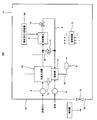
- FIG. 1 is a block diagram showing a schematic configuration of an implementation of a hydrogen generator according to Embodiment 1 and a fuel cell system including the hydrogen generator.
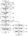
- FIG. 2 is a flowchart showing a schematic operation of the fuel cell system according to the first embodiment.
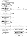
- FIG. 3 is a flowchart showing a schematic operation of the fuel cell system according to Modification 1 of Embodiment 1.
- FIG. 4 is a flowchart showing a schematic operation of the fuel cell system according to the second embodiment.
- FIG. 5 is a block diagram showing a schematic configuration of a hydrogen generator according to Embodiment 3 and a fuel cell system including the hydrogen generator.
- FIG. 6 is a flowchart showing a schematic operation of the fuel cell system according to Embodiment 3.
- the present inventors can inspect whether the CO sensor is normal or abnormal with a relatively easy configuration and operation in the CO sensor provided in the fuel cell system.
- the present inventors periodically generate carbon monoxide at a predetermined concentration in the combustion exhaust gas, and compare the output value of the CO sensor with the upper and lower threshold values set in advance, thereby making it possible to reduce CO.
- the present inventors change the air-fuel ratio, which is the ratio of the air supplied to the combustor and the combustion gas, so that carbon monoxide is contained in the combustion exhaust gas, and hydrogen is the main component as the combustion gas. It is eager to study that it is easier to generate carbon monoxide in a predetermined concentration range by supplying raw material gas than by supplying fuel gas or anode off-gas containing hydrogen that was not used in fuel cells. As a result, it obtained as knowledge.
- a hydrogen generator includes a hydrogen generator that generates hydrogen-containing fuel gas from a hydrocarbon-containing raw material gas, a combustor that heats the hydrogen generator, and a combustion gas supply that supplies combustion gas to the combustor
- a hydrogen generator comprising: an air supply device that supplies air to the combustor; a CO sensor that detects carbon monoxide contained in the combustion exhaust gas discharged from the combustor; and a controller.
- the fuel cell system of the present invention includes the hydrogen generator, and a fuel cell that generates electricity by reacting an oxidant gas and a hydrogen-containing gas supplied from the hydrogen generator.
- the “predetermined first temperature” is a temperature at which carbon is not deposited on the catalyst in the hydrogen generator even when the raw material gas is supplied to the hydrogen generator.
- the hydrogen generator according to the first embodiment includes a hydrogen generator that generates hydrogen-containing fuel gas from a hydrocarbon-containing raw material gas, a combustor that heats the hydrogen generator, and a combustion gas that is supplied to the combustor.
- a hydrogen generator comprising: a combustion gas supply device; an air supply device that supplies air to the combustor; a CO sensor that detects carbon monoxide contained in combustion exhaust gas discharged from the combustor; and a controller.
- the controller supplies a raw material gas as a combustion gas from the combustion gas supply device to the combustor, and supplies air and combustion gas to the combustor. If the CO sensor does not detect the carbon monoxide concentration at the predetermined concentration, it is determined as abnormal, notifies the abnormality, or operates the hydrogen generator. Control to stop.
- the controller when the temperature of the hydrogen generator is higher than the first temperature, the controller switches the hydrogen generator when the activation signal of the hydrogen generator is input. It does not have to start.
- the fuel cell system 100 includes the hydrogen generator and a fuel cell that generates electricity by reacting the oxidant gas and the hydrogen-containing gas supplied from the hydrogen generator.
- Embodiment 1 an example of the hydrogen generator according to Embodiment 1 and a fuel cell system including the hydrogen generator will be described with reference to FIGS. 1 and 2.
- FIG. 1 is a block diagram showing a schematic configuration of an implementation of a hydrogen generator according to Embodiment 1 and a fuel cell system including the hydrogen generator.
- the fuel cell system 100 includes a hydrogen generator 101, an oxidant gas supplier 102, and a fuel cell 3.
- the hydrogen generator 101 includes a hydrogen generator 1, a combustor 2, a raw material gas supplier 4, a CO sensor 5, a controller 6, and an alarm 14.
- the hydrogen generator 1 includes a catalyst inside, and a reformer (not shown) that generates a fuel gas that is a hydrogen-containing gas from a raw material gas by a reforming reaction.
- the reforming reaction may take any form, and examples thereof include a steam reforming reaction, an autothermal reaction, and a partial oxidation reaction.
- equipment necessary for each reforming reaction is appropriately provided in the hydrogen generator 1.
- a steam supply unit that supplies steam to the reformer is provided. If the reforming reaction is an autothermal reaction, the hydrogen generator 1 is provided with an air supply device (not shown) for supplying air to the reformer.
- a raw material gas is supplied to the hydrogen generator 1 from the outside of the fuel cell system 100 by a raw material gas supply device 4.
- the source gas is a gas containing an organic compound composed of at least carbon and hydrogen, such as city gas mainly composed of methane, natural gas, and LPG.
- the hydrogen generator 1 is provided with a temperature detector 1a that detects the temperature of the catalyst in the hydrogen generator 1, and outputs the detected temperature of the catalyst to the controller 6 described later as an electrical signal.
- the temperature detector 1a may directly detect the temperature of the catalyst, or the temperature of the gas passing through the catalyst or the temperature of the structure constituting the hydrogen generator 1 to detect the temperature of the catalyst. You may do it.
- the raw material gas supply device 4 is a device that adjusts the flow rate of the raw material gas supplied to the hydrogen generator 1, and includes, for example, a booster such as a booster pump and a flow rate adjustment valve. It may be configured. For example, a constant volume booster pump is used as the booster, but the booster is not limited to this.
- a fuel gas passage 7, which will be described later, is connected to the fuel gas outlet portion of the hydrogen generator 1, and the fuel gas generated by the hydrogen generator 1 passes through the fuel gas passage 7 and is supplied to the fuel cell 3. Is done.
- the fuel cell 3 performs power generation using the fuel gas generated by the hydrogen generator 1 and oxygen in the air that is an oxidant gas supplied from the oxidant gas supply unit 102.
- the fuel cell 3 may be any type of fuel cell.
- a polymer electrolyte fuel cell (PEFC) is used.
- a solid oxide fuel is used.
- a battery or a phosphoric acid fuel cell can also be used.
- fans such as a blower or a sirocco fan, a diaphragm air pump, or the like can be used.
- Fuel gas containing hydrogen that has not been used for power generation in the fuel cell 3 (hereinafter referred to as off-fuel gas as appropriate) is discharged from the fuel cell 3 via the off-fuel gas flow path 9. Specifically, the off-fuel gas discharged from the fuel cell 3 is supplied to the combustor 2 described later of the hydrogen generator 1 through the off-fuel gas flow path 9.
- a first on-off valve 10 is provided in the off fuel gas passage 9.
- the first on-off valve 10 may be driven by electric power, such as an electromagnetic valve, or may be driven by gas pressure, and may have any configuration as long as the off-fuel gas passage 9 can be closed or opened. It doesn't matter.
- the fuel gas flow path 7 supplies the fuel gas generated by the hydrogen generator 1 to the fuel cell 3. Specifically, one end of the fuel gas flow path 7 is connected to the fuel gas outlet of the hydrogen generator 1, and the other end is connected to the anode side of the fuel cell 3. Further, the fuel gas channel 7 is branched from the bypass channel 12 in the middle thereof.
- the bypass channel 12 supplies the fuel gas generated by the hydrogen generator 1 to the combustor 2 without passing through the fuel cell 3.
- the bypass flow path 12 is branched from the fuel gas flow path 7 and connected to the downstream side of the first on-off valve 10 of the off fuel gas flow path 9.
- the bypass channel 12 is provided with a second on-off valve 11.
- the second on-off valve 11 may be driven by electric power, such as an electromagnetic valve, or may be driven by gas pressure, and may have any configuration as long as the bypass flow path 12 can be closed or opened. Absent.
- the fuel gas flow path 7 controls the first on-off valve 10 and the second on-off valve 11 by a controller 6 to be described later, thereby opening the first on-off valve 10 and closing the second on-off valve 11.
- a controller 6 controls the first on-off valve 10 and the second on-off valve 11 by a controller 6 to be described later, thereby opening the first on-off valve 10 and closing the second on-off valve 11.
- the passage through the fuel cell 3 from the off fuel gas passage 9 to the combustor 2 and the bypass passage 12 by closing the first on-off valve 10 and opening the second on-off valve 11 are performed. It is possible to switch arbitrarily between the off-fuel gas flow path 9 and the path through which the combustor 2 flows.
- the first on-off valve 10 is installed on the fuel cell 3 side of the off fuel gas channel 9 from the junction of the off fuel gas channel and the bypass channel 12.
- the present invention is not limited to this, and it may be installed on the fuel gas channel 7 on the fuel cell 3 side with respect to the branch portion with the bypass channel 12. Further, it may be provided both upstream and downstream of the fuel cell 3, and further, instead of the first on-off valve 10 and the second on-off valve 11, a flow path switching valve such as a three-way valve is used. May be.
- the combustor 2 uses at least one of the raw material gas, the fuel gas, and the off-fuel gas as a combustion gas, and burns it with the combustion air supplied to the combustor 2 by the combustion air supply device 8, whereby the hydrogen generator 1 And the temperature of the catalyst in the hydrogen generator 1 is maintained at a temperature suitable for carrying out the catalytic reaction.
- the flue gas generated by the combustion is discharged to the outside through a flue gas passage 13 described later.
- the raw material gas supply device 4 may be used as a combustion gas supply device that supplies combustion gas to the combustor 2.
- the raw material gas that has passed through the hydrogen generator 1 may be supplied to the combustor 2, and the hydrogen generator 1 is bypassed. You may be comprised so that source gas may be supplied.
- the combustion air supply device 8 is a device that adjusts the flow rate of the combustion air supplied to the combustor 2.
- the combustion air supply device 8 includes a blower fan and a flow meter, but is not limited thereto.
- a blower may be used.
- the combustion exhaust gas flow path 13 discharges the combustion exhaust gas generated by the combustion in the combustor 2 to the outside.
- a CO sensor 5 is installed in the middle of the combustion exhaust gas passage 13. As shown in FIG. 1, the CO sensor 5 may be disposed on the flue gas passage 13 or may be disposed on a pipe that is a part of the flue gas passage 13.
- the CO sensor 5 detects the concentration of carbon monoxide in the combustion exhaust gas discharged from the combustor 2.
- a catalytic combustion type or a semiconductor type can be adopted.
- the catalytic combustion type CO sensor 5 has two heater coils inside, and a detection element added with a catalyst and a compensation element not added with a catalyst are attached to each heater coil.
- the heater coil is used to raise the temperature of the detection block and the compensation element to a temperature suitable for the detection element to catalyze carbon monoxide.
- the sensing element of the CO sensor 5 When the gas containing carbon monoxide touches the sensing element of the CO sensor 5, catalytic combustion occurs and combustion heat is generated.
- the compensation element to which no catalyst is added does not burn even when it comes into contact with the gas containing carbon monoxide, and therefore a temperature difference is generated between the sensing element and the compensation element.
- the CO sensor 5 outputs the temperature difference (resistance difference) between the two elements of the detection element and the compensation element as an electrical signal to a controller 6 described later. Since the temperature of the sensing element increases according to the concentration of carbon monoxide, the higher the carbon monoxide concentration, the more proportional the output value increases.
- the controller 6 has a function of receiving an output signal of the CO sensor 5 and appropriately controlling devices such as the raw material gas supplier 4, the first on-off valve 10, and the second on-off valve 11 that constitute the fuel cell system 100. It may be anything, and includes an arithmetic processing unit (not shown), a storage unit (not shown) for storing a control program, and a clock unit. Examples of the arithmetic processing unit include an MPU and a CPU. An example of the storage unit is a memory.
- the controller may be composed of a single controller that performs centralized control, or may be composed of a plurality of controllers that perform distributed control in cooperation with each other.
- the controller 6 receives the output signal of the CO sensor 5 and determines whether or not the CO sensor 5 is abnormal. When the controller 6 determines that the CO sensor 5 is abnormal, the controller 6 notifies the abnormality to the abnormality.
- the alarm device 14 may have any configuration as long as it can notify the outside that the CO sensor 5 is abnormal.
- a mode for informing outside for example, a mode in which character data or image data or the like is displayed on a display unit (screen) of a remote controller, a mode in which a speaker or the like is used for voice notification, light or color may be used. It may be a mode that informs by.
- the aspect notified to a smart phone, a mobile telephone, or a tablet-type computer etc. with an email or an application via a communication network may be sufficient.
- the controller 6 opens the first on-off valve 10 and the second on-off valve 11 is closed to drive the raw material gas supply device 4, so that the hydrogen generator 1 has a predetermined value.
- the raw material gas and the water vapor are supplied at a flow rate, and fuel gas is generated from the raw material gas.
- the fuel gas generated by the hydrogen generator 1 is supplied to the fuel cell 3 via the fuel gas flow path 7. Further, air is supplied as an oxidant gas to the fuel cell 3 by the oxidant gas supply device 102, and the fuel cell 3 generates power.
- the off-fuel gas containing hydrogen that has not been consumed by the power generation in the fuel cell 3 is supplied as a combustion gas to the combustor 2 through the off-fuel gas passage 9. Further, combustion air is supplied to the combustor 2 by the combustion air supply device 8 to burn off fuel gas. At this time, the heat generated in the combustor 2 is used to maintain the catalyst in the hydrogen generator 1 at a temperature suitable for generating fuel gas from the raw material gas.
- the flow rate of the raw material gas supplied by the raw material gas supply device is the flow rate necessary for power generation in the fuel cell 3 and combustion in the combustor 2 necessary for maintaining the temperature of the catalyst in the hydrogen generator 1. Is adjusted by the controller 6 so that is supplied to the hydrogen generator 1.
- the flow rate of the air supplied to the combustor 2 by the combustion air supply device 8 is controlled by the controller 6 so as to be a flow rate necessary for stably and completely burning off fuel gas supplied to the combustor 2.
- the Therefore, the combustor 2 is usually supplied with combustion air and off-fuel gas as combustion gas at a predetermined range of air-fuel ratio, and stable complete combustion is performed.
- Combustion exhaust gas generated by combustion in the combustor 2 is discharged to the outside of the fuel cell system 100 through the combustion exhaust gas passage 13.
- the controller 6 closes the first on-off valve 10 and operates the source gas supply unit 4 with the second on-off valve 11 opened, so that the source gas Start supplying.
- the raw material gas passes through the inside of the hydrogen generator 1, passes through the fuel gas passage 7, and is supplied as a combustion gas to the combustor 2 through the bypass passage 12 and the off fuel gas passage 9.
- the combustion gas supplied from the combustion air supply device 8 is used to burn the raw material gas supplied via the hydrogen generator 1, and the hydrogen generator 1 is heated with heat from the combustion heat.
- the first temperature is a temperature lower than the temperature at which carbon deposition occurs when only the raw material gas is supplied to the catalyst in the hydrogen generator 1, and may be stored in the controller 6 in advance.
- the fuel gas generated by the hydrogen generator 1 is supplied as a combustion gas to the combustor 2 and is combusted using the combustion air supplied by the combustion air supplier 8.
- the temperature of the catalyst in the hydrogen generator 1 after the start of the reforming reaction is sufficient to produce fuel gas at a predetermined conversion rate (ratio at which hydrocarbons in the raw material gas are reformed to hydrogen) or higher. While the temperature does not rise, a sufficient amount of hydrogen required for power generation by the fuel cell 3 is not generated by the hydrogen generator 1, and the fuel gas supplied from the hydrogen generator 1 contains carbon monoxide. The component which poisons the catalyst in the fuel cell 3 is included. Therefore, during the start-up operation of the fuel cell system 100, by operating the first on-off valve 10 and the second on-off valve 11, fuel gas inappropriate for supplying to the fuel cell 3 is caused to flow into the fuel cell 3. It is made to supply to the combustor 2 via the bypass flow path 12 without making it flow.
- the fuel gas is supplied to the fuel cell 3 by opening the first on-off valve 10 and closing the second on-off valve 11.
- the flow path is switched to start the power generation operation.
- the flow rate of the combustion gas and combustion air supplied to the combustor 2 is controlled by the controller 6 with the raw material gas supply device 4 and the combustion air supply device 8. 2, the air-fuel ratio is adjusted so as to be in a predetermined range so that stable complete combustion is performed.
- the “normal time” refers to a period during which the operation of a CO sensor, which will be described later, is not performed in the combustor 2 and the fuel gas and air are burning.
- the combustion exhaust gas generated by the combustion of the raw material gas in the combustor 2 is discharged to the outside of the fuel cell system 100 through the combustion exhaust gas passage 13.
- the fuel cell system 100 of the first embodiment during normal combustion during power generation operation and start-up operation, for example, incombustion occurs due to a problem that the flow rate of combustion air shifts in the combustor 2,
- the CO sensor 5 provided in the combustion exhaust gas flow path 13 detects it, and when the concentration of carbon monoxide is higher than a predetermined concentration, the controller 6
- the flow rate of at least one of the source gas and the combustion air is adjusted, or the operation of the fuel cell system 100 is stopped. For this reason, it is important to inspect whether the CO sensor 5 is operating normally.
- FIG. 2 is a flowchart showing a schematic operation of the fuel cell system according to the first embodiment.
- the controller 6 confirms whether or not an operation command has been input to the fuel cell system 100 (hydrogen generator 101) (step S101).
- an operation command is input to the fuel cell system 100
- a remote controller not shown
- a case where the operation start time of the fuel cell system 100 set in advance is reached may be mentioned.
- Step S101 When the operation command for the fuel cell system 100 is not input (No in Step S101), the controller 6 repeats Step S101 until the operation command for the fuel cell system 100 is input.
- Step S101 When the operation command is input to the fuel cell system 100 (Yes in Step S101), the controller 6 proceeds to Step S102.
- step S102 the controller 6 confirms whether or not the temperature T of the catalyst in the hydrogen generator 1 detected by the temperature detector 1a is equal to or lower than the first temperature T1.
- the first temperature T1 is a temperature at which no carbon deposition occurs even when only the raw material gas is supplied to the catalyst in the hydrogen generator 1.
- the controller 6 waits for the start of the fuel cell system 100 until the temperature T of the catalyst becomes equal to or lower than the first temperature T1. .
- the controller 6 prohibits the activation of the hydrogen generator 101 and the fuel cell system 100 and ends this program. Also good.
- step S102 when the temperature T of the catalyst is lower than the first temperature T1 (Yes in step S102), the controller 6 proceeds to the next step S103.
- step S103 the controller 6 starts the starting operation of the fuel cell system 100. Specifically, the first on-off valve 10 is closed (opened), the second on-off valve 11 is opened, and the flow path is such that the source gas is supplied to the combustor 2 via the bypass flow path 12.
- the combustion air supply device 8 and the raw material gas supply device 4 are driven to supply the combustion air and the raw material gas as the combustion gas to the combustor 2. In the combustor 2, the combustion air and the combustion gas are ignited and combustion is started.
- the controller 6 controls the raw material gas supply device 4 and the combustion air supply device 8 so that the air-fuel ratio in the combustor 2 becomes the first air-fuel ratio (predetermined range) that enables stable and complete combustion.
- the air-fuel ratio in which carbon monoxide is not generated in the combustion exhaust gas in the combustor 2 to be used in advance. can be obtained experimentally.
- the air-fuel ratio at the time of ignition in the combustor 2 may be an air-fuel ratio different from the first air-fuel ratio that is the air-fuel ratio after ignition.
- the controller 6 causes the air-fuel ratio, which is the ratio of the combustion air supplied to the combustor 2 and the raw material gas, to deviate from a predetermined range to become the second air-fuel ratio. Then, the flow rate is changed by controlling at least one of the raw material gas supply device 4 and the combustion air supply device 8 (step S104). Thereby, in the combustor 2, incomplete combustion occurs and carbon monoxide is generated.
- the second air-fuel ratio is experimentally determined in advance as an air-fuel ratio in which the carbon monoxide concentration in the combustion exhaust gas is between the lower threshold (A) and the upper threshold (B) when the air-fuel ratio is changed. Can be sought.
- the second air-fuel ratio it is better to set the second air-fuel ratio to a higher air-fuel ratio than the first air-fuel ratio. This is because when the air-fuel ratio is shifted to a lower ratio side than the first air-fuel ratio, the carbon monoxide concentration in the combustion exhaust gas rapidly rises compared to 2, the air-fuel ratio is shifted to a higher ratio side. This is because the carbon monoxide concentration rises relatively slowly. However, if the air-fuel ratio is excessively increased, there is a risk of extinguishing the fire, so it is necessary to sufficiently grasp the combustion characteristics of the combustor 2 to be used.
- the lower limit threshold (A) is equal to or higher than the lower limit concentration detectable by the CO sensor 5, the upper limit threshold (B) is detectable by the CO sensor 5, and the air-fuel ratio is changed to the second air-fuel ratio. Even if it continues to be discharged, the concentration is set so that it does not affect the human body.
- the lower limit threshold (A) may be 100 ppm, for example.
- an upper limit threshold value (B) 500 ppm may be sufficient and 2400 ppm may be sufficient, for example.
- the controller 6 determines whether or not the concentration C of carbon monoxide in the combustion exhaust gas detected by the CO sensor 5 is within a predetermined concentration range between the lower limit threshold (A) and the upper limit threshold (B). Determination is made (step S105). When the concentration C detected by the CO sensor 5 is within a predetermined range (Yes in step S105), the controller 6 determines that the CO sensor 5 is normal (step S106) and sets the air-fuel ratio to the first level. Returning to the air-fuel ratio, the starting operation is continued (step S107), and this program is terminated.
- the controller 6 determines that the CO sensor 5 is abnormal (step S108), and the alarm device 14 Is informed that the CO sensor 5 is abnormal (step S109). Next, the controller 6 stops the fuel cell system 100 (step S110), and ends this program.
- the controller 6 may be configured to prohibit the restart of the fuel cell system 100 after stopping the fuel cell system 100 in step S110.
- the CO sensor 5 that monitors the carbon monoxide concentration in the combustion exhaust gas during the start-up operation in which combustion is started in the combustor 2 of the fuel cell system 100 is provided. Since it is possible to inspect whether it is normal or abnormal, it is possible to provide a highly safe fuel cell system.
- the operation of the CO sensor 5 is confirmed by changing the air-fuel ratio in the combustor 2 so that the combustion exhaust gas contains carbon monoxide. Since no equipment is required, it is possible to check the operation relatively easily.
- the raw material gas is supplied to the combustor 2 as a combustion gas to change the air-fuel ratio and carbon monoxide is contained in the combustion exhaust gas, the concentration of carbon monoxide is easily stabilized within a predetermined range, By not generating carbon within a predetermined range, it is possible to suppress the possibility of erroneous detection that determines that the CO sensor 5 is abnormal even though it is normal.
- the material gas is allowed to flow through the hydrogen generator 1, so that carbon is deposited on the catalyst and the performance of the hydrogen generator 1 deteriorates. Can be suppressed.
- the fuel cell system 100 when the CO sensor 5 is determined to be abnormal, the fuel cell system 100 is stopped, so that a highly safe fuel cell system can be provided.
- the hydrogen generator 1 is provided with the temperature detector 1a that detects the catalyst temperature in the hydrogen generator 1, but the embodiment is not limited thereto.
- the time after the fuel cell system 100 shifts from the power generation operation to the stop operation (after the operation stop signal of the fuel cell system 100 (hydrogen generator 101) is input) and the combustion in the combustor 2 ends.
- the correlation with the temperature of the catalyst in the hydrogen generator 1 is experimentally obtained, stored in the controller 6 in advance, and when a predetermined time (first time) has elapsed after the combustion is finished, the CO The operation of the sensor 5 may be confirmed.
- the mode in which the operation check of the CO sensor 5 is executed after the start signal of the fuel cell system 100 is input to the controller 6 is adopted.
- a mode in which an operation stop signal of the fuel cell system 100 is input to the controller 6 and the operation check of the CO sensor 5 is executed while the stop operation is executed may be adopted.
- the operation check of the CO sensor 5 is performed. You may employ
- the hydrogen generator of Modification 1 in Embodiment 1 includes a hydrogen generator that generates fuel gas containing hydrogen from a raw material gas containing hydrocarbons, a combustor that heats the hydrogen generator, and a combustion gas in the combustor.
- a combustion gas supply device that supplies air
- an air supply device that supplies air to the combustor
- a CO sensor that detects carbon monoxide contained in the combustion exhaust gas discharged from the combustor
- the generator is a generator that supplies a raw material gas as a combustion gas from the combustion gas supply device to the combustor when a predetermined first time has elapsed after the combustion in the combustor ends.
- the air-fuel ratio which is the ratio between the supplied air and the combustion gas
- the CO sensor does not detect the carbon monoxide concentration at the predetermined concentration, it is determined as abnormal, and the abnormality is notified.
- the hydrogen generator Control so as to stop the rolling.
- the controller turns off the hydrogen generator when a start signal of the hydrogen generator is input before the first time elapses after the combustion in the combustor ends. It does not have to start.
- FIG. 3 is a flowchart showing a schematic operation of the fuel cell system according to Modification 1 of Embodiment 1.
- step S102 the operation of the fuel cell system 100 of the first modification is basically the same as the operation of the fuel cell system 100 according to the first embodiment, but instead of step S102, step S102a is performed.
- the point to execute is different.
- step S102a the controller 6 determines whether or not the first time has elapsed after the combustion in the combustor 2 is completed.
- the first time is obtained in advance by an experiment or the like, and is set as the time from when the combustion operation of the combustion gas in the combustor 2 is completed until the hydrogen generator 1 becomes the first temperature or less.
- the controller 6 determines that the hydrogen generator 1 has become the first temperature or lower. be able to.
- the mode in which the operation check of the CO sensor 5 is performed after the activation signal of the fuel cell system 100 is input to the controller 6 is adopted, but the present invention is not limited to this.
- a mode in which an operation stop signal of the fuel cell system 100 is input to the controller 6 and the operation check of the CO sensor 5 is executed while the stop operation is executed may be adopted.
- a mode in which the operation check of the CO sensor 5 is executed when the fuel cell system 100 is in a standby state may be adopted.
- the controller sets the hydrogen generator to the first temperature when the temperature of the hydrogen generator is higher than the first temperature and the start signal of the hydrogen generator is input. It is configured to cool below.
- the controller may be configured to supply air from the air supplier to the combustor and to cool the hydrogen generator to a first temperature or lower.
- FIG. 4 is a flowchart showing a schematic operation of the fuel cell system according to the second embodiment.
- the controller 6 confirms whether or not an operation command is input to the fuel cell system 100 (step S201).
- Step S201 When the operation command for the fuel cell system 100 is not input (No in Step S201), the controller 6 repeats Step S201 until the operation command for the fuel cell system 100 is input.
- step S201 When the operation command is input to the fuel cell system 100 (Yes in step S201), the controller 6 proceeds to step S202.
- step S202 the controller 6 confirms whether or not the temperature T of the catalyst in the hydrogen generator 1 detected by the temperature detector 1a is equal to or lower than the first temperature T1.
- the first temperature T1 is a temperature at which no carbon deposition occurs even when only the raw material gas is supplied to the catalyst in the hydrogen generator 1.
- step S202 When the temperature T is higher than the first temperature T1 (No in step S202), the controller 6 proceeds to step S211.
- step S211 the controller 6 starts the cooling of the catalyst in the hydrogen generator 1 by operating the combustion air supplier 8 and supplying air to the combustor 2. Then, the controller 6 returns to step S202 and continues cooling until the temperature T becomes equal to or lower than the first temperature T1 (Yes in step S202).
- step S203 when the temperature T of a catalyst is lower than 1st temperature T1 (it is Yes at step S202). Since the flow from step S203 to step S210 is the same as the flow from step S103 to step 110 in the first embodiment, a description thereof will be omitted.
- the combustion air supplier 8 supplies air to the combustor 2 to cool the catalyst in the hydrogen generator 1.
- the time for the temperature T of the catalyst in the vessel 1 to fall below T1 can be shortened, and the time from the input of the operation command to the start-up can be shortened.
- the controller sets the hydrogen generator to the first temperature when the temperature of the hydrogen generator is higher than the first temperature and the start signal of the hydrogen generator is input. It is configured to cool below.
- the fuel cell system according to Embodiment 3 includes the hydrogen generator, a fuel cell that generates electricity by reacting the oxidant gas and the hydrogen-containing gas supplied from the hydrogen generator, a hydrogen generator, and combustion.
- a housing that houses the battery and a ventilator that ventilates the inside of the housing are provided, and the controller is configured to operate the ventilator and cool the hydrogen generator to a first temperature or lower.
- FIG. 5 is a block diagram showing a schematic configuration of a hydrogen generator according to Embodiment 3 and a fuel cell system including the hydrogen generator.
- the fuel cell system 100 according to the third embodiment has the same basic configuration as the fuel cell system 100 according to the first embodiment, but houses a hydrogen generator 101 and the like. The difference is that a housing 15 and a ventilator 17 are further provided.
- the housing 15 accommodates each device other than the alarm device 14 constituting the fuel cell system 100.
- the casing 15 is provided with an exhaust port 16 and an air supply port 17 so as to communicate with the outside air, and a ventilator 18 is disposed in the vicinity of the exhaust port 16.
- the ventilator 18 is configured to ventilate the inside of the housing 15, and for example, a fan or the like can be used.
- the ventilator 18 may be provided in the vicinity of the air supply port 17.
- FIG. 6 is a flowchart showing a schematic operation of the fuel cell system according to the third embodiment.
- step S211a the operation of the fuel cell system 100 according to the third embodiment is basically the same as that of the fuel cell system 100 according to the second embodiment, but instead of step S211, step S211a is performed.
- the point to execute is different. Specifically, the controller 6 starts the cooling of the catalyst in the hydrogen generator 1 by operating the ventilator 18 and ventilating the inside of the housing 15 (step S211a).
- the hydrogen generator according to the present invention, the fuel cell system including the hydrogen generator, the operation method of the hydrogen generator, and the operation method of the fuel cell system are more useful in the field of fuel cells because the operation of the CO sensor can be confirmed than before. is there.
Landscapes
- Chemical & Material Sciences (AREA)
- Chemical Kinetics & Catalysis (AREA)
- Engineering & Computer Science (AREA)
- General Chemical & Material Sciences (AREA)
- Sustainable Energy (AREA)
- Sustainable Development (AREA)
- Manufacturing & Machinery (AREA)
- Electrochemistry (AREA)
- Life Sciences & Earth Sciences (AREA)
- Organic Chemistry (AREA)
- Health & Medical Sciences (AREA)
- General Health & Medical Sciences (AREA)
- Combustion & Propulsion (AREA)
- Inorganic Chemistry (AREA)
- Fuel Cell (AREA)
- Hydrogen, Water And Hydrids (AREA)
Abstract
La présente invention concerne un dispositif de production d'hydrogène pourvu : d'un générateur d'hydrogène (1) ; d'une chambre de combustion (2) qui chauffe le générateur d'hydrogène (1) ; d'une alimentation en gaz de combustion ; d'une alimentation en air (8) ; d'un capteur de CO (5) qui détecte le monoxyde de carbone compris dans le gaz d'échappement de combustion ; et d'un organe de commande (6) qui exécute une commande de façon à délivrer un gaz de matière brute à la chambre de combustion (2) à partir d'une alimentation en gaz de combustion en tant que gaz de combustion lorsque la température du générateur d'hydrogène (1) est égale ou inférieure à une première température prédéterminée ou lorsqu'un premier temps prédéterminé se soit passé après la fin de la combustion dans la chambre de combustion (2) et de sorte que le rapport air-combustible, qui est le rapport de l'air au gaz de combustion délivré à la chambre de combustion (2), se situe en dehors d'une plage prédéfinie, et qui exécute une commande telle qu'une anomalie est déterminée, qu'une notification d'une anomale est fournie, ou que le fonctionnement du dispositif de production d'hydrogène (101) est arrêté lorsque le capteur de CO (5) ne détecte pas de concentration de monoxyde de carbone qui est une concentration prédéfinie.
Priority Applications (2)
| Application Number | Priority Date | Filing Date | Title |
|---|---|---|---|
| EP14775508.6A EP2980902B1 (fr) | 2013-03-28 | 2014-03-07 | Dispositif de production d'hydrogène, système de pile à combustible comprenant de ce dernier, procédé de mise en oeuvre du dispositif de production d'hydrogène, et procédé de mise en oeuvre du système de pile à combustible |
| JP2014528725A JP5853154B2 (ja) | 2013-03-28 | 2014-03-07 | 水素生成装置、それを備える燃料電池システム、水素生成装置の運転方法、及び燃料電池システムの運転方法 |
Applications Claiming Priority (2)
| Application Number | Priority Date | Filing Date | Title |
|---|---|---|---|
| JP2013-068103 | 2013-03-28 | ||
| JP2013068103 | 2013-03-28 |
Publications (1)
| Publication Number | Publication Date |
|---|---|
| WO2014155996A1 true WO2014155996A1 (fr) | 2014-10-02 |
Family
ID=51623017
Family Applications (1)
| Application Number | Title | Priority Date | Filing Date |
|---|---|---|---|
| PCT/JP2014/001291 Ceased WO2014155996A1 (fr) | 2013-03-28 | 2014-03-07 | Dispositif de production d'hydrogène, système de pile à combustible pourvu de ce dernier, procédé de mise en œuvre du dispositif de production d'hydrogène, et procédé de mise en œuvre du système de pile à combustible |
Country Status (3)
| Country | Link |
|---|---|
| EP (1) | EP2980902B1 (fr) |
| JP (1) | JP5853154B2 (fr) |
| WO (1) | WO2014155996A1 (fr) |
Cited By (1)
| Publication number | Priority date | Publication date | Assignee | Title |
|---|---|---|---|---|
| WO2018173620A1 (fr) * | 2017-03-21 | 2018-09-27 | パナソニックIpマネジメント株式会社 | Système de piles à combustible |
Citations (5)
| Publication number | Priority date | Publication date | Assignee | Title |
|---|---|---|---|---|
| JP2004093204A (ja) | 2002-08-29 | 2004-03-25 | Honda Motor Co Ltd | ガスセンサ |
| JP2005026059A (ja) * | 2003-07-02 | 2005-01-27 | Matsushita Electric Ind Co Ltd | 燃料電池システムとこれに用いる酸素センサの製造方法もしくは加熱駆動方法 |
| JP2009031080A (ja) * | 2007-07-26 | 2009-02-12 | Miura Co Ltd | 有害物質低減システムおよび燃焼装置 |
| WO2010010699A1 (fr) | 2008-07-25 | 2010-01-28 | トヨタ自動車株式会社 | Système de pile à combustible et procédé de commande de pile à combustible |
| JP2011256059A (ja) * | 2010-06-07 | 2011-12-22 | Panasonic Corp | 水素生成装置および燃料電池システムの運転方法 |
Family Cites Families (4)
| Publication number | Priority date | Publication date | Assignee | Title |
|---|---|---|---|---|
| JPH0763329A (ja) * | 1993-08-30 | 1995-03-07 | Gastar Corp | Coセンサ付燃焼機におけるcoセンサの動作点検方法 |
| EP1850415B1 (fr) * | 2005-02-18 | 2012-12-12 | Panasonic Corporation | Systeme de pile a combustible |
| CN101918306B (zh) * | 2008-11-20 | 2012-11-07 | 松下电器产业株式会社 | 氢生成装置以及具备其的燃料电池系统 |
| US9685672B2 (en) * | 2012-12-19 | 2017-06-20 | Panasonic Intellectual Property Management Co., Ltd. | Hydrogen generation apparatus, fuel cell system including the same, method of operating hydrogen generation apparatus and method of operating fuel cell system |
-
2014
- 2014-03-07 EP EP14775508.6A patent/EP2980902B1/fr active Active
- 2014-03-07 WO PCT/JP2014/001291 patent/WO2014155996A1/fr not_active Ceased
- 2014-03-07 JP JP2014528725A patent/JP5853154B2/ja not_active Expired - Fee Related
Patent Citations (5)
| Publication number | Priority date | Publication date | Assignee | Title |
|---|---|---|---|---|
| JP2004093204A (ja) | 2002-08-29 | 2004-03-25 | Honda Motor Co Ltd | ガスセンサ |
| JP2005026059A (ja) * | 2003-07-02 | 2005-01-27 | Matsushita Electric Ind Co Ltd | 燃料電池システムとこれに用いる酸素センサの製造方法もしくは加熱駆動方法 |
| JP2009031080A (ja) * | 2007-07-26 | 2009-02-12 | Miura Co Ltd | 有害物質低減システムおよび燃焼装置 |
| WO2010010699A1 (fr) | 2008-07-25 | 2010-01-28 | トヨタ自動車株式会社 | Système de pile à combustible et procédé de commande de pile à combustible |
| JP2011256059A (ja) * | 2010-06-07 | 2011-12-22 | Panasonic Corp | 水素生成装置および燃料電池システムの運転方法 |
Cited By (2)
| Publication number | Priority date | Publication date | Assignee | Title |
|---|---|---|---|---|
| WO2018173620A1 (fr) * | 2017-03-21 | 2018-09-27 | パナソニックIpマネジメント株式会社 | Système de piles à combustible |
| JPWO2018173620A1 (ja) * | 2017-03-21 | 2020-01-30 | パナソニックIpマネジメント株式会社 | 燃料電池システム |
Also Published As
| Publication number | Publication date |
|---|---|
| EP2980902A1 (fr) | 2016-02-03 |
| EP2980902B1 (fr) | 2018-05-02 |
| EP2980902A4 (fr) | 2016-02-03 |
| JPWO2014155996A1 (ja) | 2017-02-16 |
| JP5853154B2 (ja) | 2016-02-09 |
Similar Documents
| Publication | Publication Date | Title |
|---|---|---|
| US9685672B2 (en) | Hydrogen generation apparatus, fuel cell system including the same, method of operating hydrogen generation apparatus and method of operating fuel cell system | |
| JP5349048B2 (ja) | 水素生成装置、水素生成装置の運転方法、及び燃料電池システム | |
| US20120021313A1 (en) | Fuel cell system and method for operating the same | |
| JP5336022B2 (ja) | 発電システム及びその運転方法 | |
| KR101365326B1 (ko) | 발전 시스템 및 그 운전 방법 | |
| JP5874022B2 (ja) | 発電システムおよびその運転方法 | |
| WO2012081220A1 (fr) | Système de génération de puissance, et procédé de fonctionnement associé | |
| JP2009217951A (ja) | 燃料電池システム | |
| EP2677585B1 (fr) | Système de génération d'électricité et son procédé de fonctionnement | |
| US20130149623A1 (en) | Fuel cell system and method of operating the same | |
| JP2009211972A (ja) | 燃料電池システム | |
| JP2010238520A (ja) | 燃料電池システム | |
| KR20140009905A (ko) | 발전 시스템 및 그 운전 방법 | |
| JP5853154B2 (ja) | 水素生成装置、それを備える燃料電池システム、水素生成装置の運転方法、及び燃料電池システムの運転方法 | |
| US9791154B2 (en) | Power generation system and method of operating power generation system | |
| WO2012132259A1 (fr) | Système de pile à combustible et son procédé de fonctionnement | |
| JP2014214049A (ja) | 水素生成装置 | |
| WO2012132260A1 (fr) | Système de pile à combustible et son procédé de fonctionnement | |
| JP5147198B2 (ja) | 燃料電池システム | |
| JP6218009B2 (ja) | 水素生成装置及び燃料電池システム | |
| JP2012059559A (ja) | 燃料電池システム | |
| JP2016132585A (ja) | 水素生成装置およびそれを用いた燃料電池システム並びにその運転方法 | |
| JP2012204224A (ja) | 燃料電池システムとその運転方法 |
Legal Events
| Date | Code | Title | Description |
|---|---|---|---|
| ENP | Entry into the national phase |
Ref document number: 2014528725 Country of ref document: JP Kind code of ref document: A |
|
| 121 | Ep: the epo has been informed by wipo that ep was designated in this application |
Ref document number: 14775508 Country of ref document: EP Kind code of ref document: A1 |
|
| WWE | Wipo information: entry into national phase |
Ref document number: 2014775508 Country of ref document: EP |
|
| NENP | Non-entry into the national phase |
Ref country code: DE |