WO2014162402A1 - Dispositif d'introduction d'éléments - Google Patents
Dispositif d'introduction d'éléments Download PDFInfo
- Publication number
- WO2014162402A1 WO2014162402A1 PCT/JP2013/059858 JP2013059858W WO2014162402A1 WO 2014162402 A1 WO2014162402 A1 WO 2014162402A1 JP 2013059858 W JP2013059858 W JP 2013059858W WO 2014162402 A1 WO2014162402 A1 WO 2014162402A1
- Authority
- WO
- WIPO (PCT)
- Prior art keywords
- rail
- spring
- supply device
- magnet
- side end
- Prior art date
- Legal status (The legal status is an assumption and is not a legal conclusion. Google has not performed a legal analysis and makes no representation as to the accuracy of the status listed.)
- Ceased
Links
Images

Classifications
-
- B—PERFORMING OPERATIONS; TRANSPORTING
- B65—CONVEYING; PACKING; STORING; HANDLING THIN OR FILAMENTARY MATERIAL
- B65G—TRANSPORT OR STORAGE DEVICES, e.g. CONVEYORS FOR LOADING OR TIPPING, SHOP CONVEYOR SYSTEMS OR PNEUMATIC TUBE CONVEYORS
- B65G47/00—Article or material-handling devices associated with conveyors; Methods employing such devices
- B65G47/02—Devices for feeding articles or materials to conveyors
- B65G47/04—Devices for feeding articles or materials to conveyors for feeding articles
- B65G47/12—Devices for feeding articles or materials to conveyors for feeding articles from disorderly-arranged article piles or from loose assemblages of articles
- B65G47/14—Devices for feeding articles or materials to conveyors for feeding articles from disorderly-arranged article piles or from loose assemblages of articles arranging or orientating the articles by mechanical or pneumatic means during feeding
- B65G47/1407—Devices for feeding articles or materials to conveyors for feeding articles from disorderly-arranged article piles or from loose assemblages of articles arranging or orientating the articles by mechanical or pneumatic means during feeding the articles being fed from a container, e.g. a bowl
- B65G47/1442—Devices for feeding articles or materials to conveyors for feeding articles from disorderly-arranged article piles or from loose assemblages of articles arranging or orientating the articles by mechanical or pneumatic means during feeding the articles being fed from a container, e.g. a bowl by means of movement of the bottom or a part of the wall of the container
- B65G47/1471—Movement in one direction, substantially outwards
-
- B—PERFORMING OPERATIONS; TRANSPORTING
- B23—MACHINE TOOLS; METAL-WORKING NOT OTHERWISE PROVIDED FOR
- B23P—METAL-WORKING NOT OTHERWISE PROVIDED FOR; COMBINED OPERATIONS; UNIVERSAL MACHINE TOOLS
- B23P19/00—Machines for simply fitting together or separating metal parts or objects, or metal and non-metal parts, whether or not involving some deformation; Tools or devices therefor so far as not provided for in other classes
- B23P19/001—Article feeders for assembling machines
- B23P19/004—Feeding the articles from hoppers to machines or dispensers
-
- B—PERFORMING OPERATIONS; TRANSPORTING
- B65—CONVEYING; PACKING; STORING; HANDLING THIN OR FILAMENTARY MATERIAL
- B65G—TRANSPORT OR STORAGE DEVICES, e.g. CONVEYORS FOR LOADING OR TIPPING, SHOP CONVEYOR SYSTEMS OR PNEUMATIC TUBE CONVEYORS
- B65G47/00—Article or material-handling devices associated with conveyors; Methods employing such devices
- B65G47/22—Devices influencing the relative position or the attitude of articles during transit by conveyors
- B65G47/24—Devices influencing the relative position or the attitude of articles during transit by conveyors orientating the articles
- B65G47/248—Devices influencing the relative position or the attitude of articles during transit by conveyors orientating the articles by turning over or inverting them
-
- B—PERFORMING OPERATIONS; TRANSPORTING
- B65—CONVEYING; PACKING; STORING; HANDLING THIN OR FILAMENTARY MATERIAL
- B65G—TRANSPORT OR STORAGE DEVICES, e.g. CONVEYORS FOR LOADING OR TIPPING, SHOP CONVEYOR SYSTEMS OR PNEUMATIC TUBE CONVEYORS
- B65G54/00—Non-mechanical conveyors not otherwise provided for
- B65G54/02—Non-mechanical conveyors not otherwise provided for electrostatic, electric, or magnetic
-
- B—PERFORMING OPERATIONS; TRANSPORTING
- B65—CONVEYING; PACKING; STORING; HANDLING THIN OR FILAMENTARY MATERIAL
- B65G—TRANSPORT OR STORAGE DEVICES, e.g. CONVEYORS FOR LOADING OR TIPPING, SHOP CONVEYOR SYSTEMS OR PNEUMATIC TUBE CONVEYORS
- B65G27/00—Jigging conveyors
- B65G27/10—Applications of devices for generating or transmitting jigging movements
- B65G27/16—Applications of devices for generating or transmitting jigging movements of vibrators, i.e. devices for producing movements of high frequency and small amplitude
Definitions
- the present invention relates to a member supply device that automatically supplies a member with a hook.
- Patent Documents 1 and 2 disclose automatic feeders for coil springs.
- the hooks are aligned in a state where the member is finally supplied to the operator.
- An object of this invention is to provide the member supply apparatus which can supply a member with a hook automatically with the direction of a hook aligned with respect to an operator.
- the invention according to claim 1 is a member supply device, comprising: a supply mechanism that acquires and supplies a member with a hook of magnetic material; and a transport mechanism that transports the member supplied from the supply mechanism.
- the transport mechanism includes: a rail on which the member is transported; a transport drive unit that transports the member along the rail; and a discharge-side end that is an end of the rail on which the member is discharged. And a magnet installed in the vicinity.
- a member supply device includes a supply mechanism that acquires and supplies a magnetic member with a hook, and a transport mechanism that transports the member supplied from the supply mechanism.
- the transport mechanism includes: a rail on which the member is transported; a transport drive unit that transports the member along the rail; and a discharge-side end that is an end of the rail on which the member is discharged. And a magnet installed in the vicinity.
- the above-mentioned member supply device provides the worker with a member with a hook.
- An example of the member is a spring.
- the member supplied by the supply mechanism is transported by the transport mechanism.
- a conveyance mechanism has a rail, a conveyance drive part, and a magnet.
- the member supplied by the supply mechanism is transported along the rail by the operation of the transport driving unit.
- a magnet is installed at the end of the rail on the side where the member is discharged, and the member is discharged under the influence of the magnet and the hooks are aligned. Therefore, the operator can easily take the hook, and the workability is improved.
- At least a part of the discharge-side end portion of the rail is cylindrical.
- the member since at least a part of the discharge side end is cylindrical, even when the member is affected by the magnet near the discharge side end, the member stands on the rail or faces in various directions. It is possible to prevent it from getting stuck.
- Another aspect of the above-described member supply apparatus includes a sensor that detects that the member is in a predetermined position near the discharge side end of the rail, and the transport driving unit detects the member by the sensor. When this happens, the conveyance of the member is stopped. When the sensor detects the ejected state of the member, the conveyance of the member is stopped, so that the operator can easily take the member.
- the transport driving unit starts transporting the member when the sensor does not detect the member.
- the sensor detects this and starts conveying the member, so that the next member is sent to the discharge side end of the rail and discharged.
- the magnet is provided directly below the discharge side end.
- the magnetic lines of force of the magnet at the discharge side end are substantially parallel to the direction in which the rail extends.
- the discharge side end portion of the rail is inclined downward. Thereby, the said member can be conveyed smoothly on a rail.
- the transport driving unit applies vibration to the member on the rail. Thereby, the said member can be conveyed more smoothly on a rail.
- the supply mechanism includes a member storage portion that stores the member and a pick-up mechanism that picks up the member from the member storage portion.
- the member is picked up from the member accommodating portion and supplied to the transport mechanism.
- the members in the following embodiments are specifically springs, and hooks made of a magnetic material are provided at both ends of the springs.
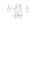
- FIG. 1 shows a spring with a hook that is handled by the spring supply device of the embodiment.
- FIG. 1A is a side view of the hooked spring 10.
- the spring 10 with a hook includes a cylindrical main body 10a and hooks 10b provided at both ends of the main body 10a in the length direction.
- the hook-attached spring 10 is attached by hooking hooks 10b at both ends to predetermined positions.
- FIG. 1 (B) is a view of the hooked spring 10 as viewed in the direction of arrow 91 in FIG. 1 (A).
- the hook 10b on the front side of the main body 10a is directed in the vertical direction, that is, the direction perpendicular to the ground.
- FIG. 1 (C) shows a state where the hooked spring 10 is rotated 90 ° in the circumferential direction of the main body 10a from the state shown in FIG. 1 (A).
- the hooks 10b at both ends of the main body appear to be linear.
- FIG. 1D is a view of the hooked spring 10 when viewed in the direction of the arrow 92 in FIG.
- a hook 10b on the front side of the main body 10a is oriented in the lateral direction, that is, in a direction parallel to the ground.
- the hooked spring 10 is simply referred to as “spring 10”.
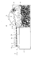
- FIG. 2 is a side view of the spring supply device 20
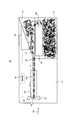
- FIG. 3 is a plan view of the spring supply device 20 as viewed from above in FIG.
- the spring supply device 20 includes a base 21, a spring accommodating portion 22, a conveyance slope 23, a roller 24, a conveyance bridge 25, a rail 30, a magnet 31, and a sensor 32.
- the control unit 35 is provided.
- the base 21 is a base of the spring supply device 20.
- the spring accommodating portion 22 is a box-shaped container and accommodates a large number of springs 10 to be transported.
- a roller 24 is provided in the spring accommodating portion 22.
- the roller 24 is driven by a drive unit 26 including a motor, and rotates in the direction of an arrow 94 about the rotation shaft 24c.
- the roller 24 includes a plurality of groove portions 24a formed at predetermined intervals in the circumferential direction, and an outer wall 24b.
- the groove 24 a has a role of picking up the spring 10 accommodated in the spring accommodating portion 22.
- it is preferable that the groove part 24a has some inclination toward the conveyance slope 23 side.
- roller 24 When the roller 24 rotates and one groove portion 24a enters the multiple springs 10 in the spring accommodating portion 22, several springs 10 enter the groove portions 24a. Thereafter, the rotation of the roller 24 causes the groove 24 a to rise as indicated by an arrow 95, and when reaching a position higher than the conveyance slope 23, the spring 10 that has entered the groove 24 a slides down on the conveyance slope 23. Thus, the roller 24 picks up the spring 10 in the spring accommodating portion 22 onto the conveying slope.
- the roller 24 is an example of a supply mechanism and a pick-up mechanism of the present invention.
- the conveyance slope 23 is provided on the base 21 and has a role of supplying the spring 10 to the conveyance bridge 25. As shown in FIG. 2, the conveyance slope 23 has an inclination that descends as it approaches the rail 30. As shown in FIG. 3, the conveyance slope 23 becomes narrower as it approaches the rail 30. Further, a drive unit 26 including a motor is provided below the conveyance slope 23.
- the drive unit 26 includes a motor, rotates the roller 24, and applies vibration to the conveyance slope 23.
- the driving unit 26 is controlled to be turned on / off by the control unit 35. Therefore, the control unit 35 controls the rotation of the roller 24 and the vibration of the transport slope 23.
- the drive unit 26 is an example of a transport drive unit according to the present invention.
- the plurality of springs 10 supplied to the conveyance slope 23 by the rollers 24 gradually move toward the rail 30 due to the inclination and vibration of the conveyance slope 23. Since the conveyance slope 23 becomes narrower as it approaches the rail 30, the springs 10 are aligned in a row in front of the conveyance bridge 25. Thus, the springs 10 are supplied to the transport bridge 25 in a state of being aligned in a row.
- the transport bridge 25 is provided on the base 21 and has a role of passing the spring 10 received from the transport slope 23 to the rail 30. As shown in FIG. 2, the transport bridge 25 also has an inclination that descends toward the rail 30. Due to the vibration of the conveyance slope 23, the plurality of springs 10 aligned in a row are sequentially pushed out of the conveyance slope 23, passed over the conveyance bridge 25, and supplied to the rail 30.
- the rail 30 is provided on the base 21 and has a role of finally providing the spring 10 to the operator.
- the rail 30 has a cylindrical through hole 30a provided in the length direction, and the spring 10 is conveyed through the through hole 30a.
- the end 30c of the rail 30 on the conveyance bridge 25 side, that is, the side on which the spring 10 is inserted is referred to as an “insertion end”, and the end 30b on the rail 30 on which the spring 10 is discharged is referred to as the “discharge end”. Part ".
- the through hole 30a is also formed to be inclined so as to gradually descend from the insertion side end 30c to the discharge side end 30b.
- the spring 10 entering the through hole 30a from the insertion side end 30c moves to the discharge side end 30b due to the force of feeding the spring 10 in which the vibration of the conveying slope 23 is aligned and the inclination of the through hole 20a.
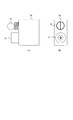
- the magnet 31 is provided at the discharge side end 30b of the rail 30.
- 4 is a view of the vicinity of the discharge side end 30b of the rail 30 in the direction of the arrow 93 in FIGS.
- the discharge side end 30b of the rail 30 has an outlet of the through hole 30a, and a magnet 31 is provided directly below the outlet.
- the magnet 31 has an annular shape, and is attached to the rail 30 by inserting a screw 33 into a central hole.
- the spring 10 discharged from the through hole 30a is rotated so that the hook 10b is in the vertical direction, that is, the direction perpendicular to the ground.
- the spring 10 conveyed to the vicinity of the discharge side end 30 b of the through hole 30 a receives the magnetic force of the magnet 31, and the portion of the hook 10 b of the spring 10 closest to the magnet 31 is attracted to the magnet 31.
- the spring 10 rotates in the through hole 30a and is discharged from the outlet of the through hole 30a with the hook 10b in the vertical direction.
- the through hole 30a has a role of preventing the spring 10 from rising or facing in various directions due to the influence of the magnet 31 when the spring 10 is conveyed by the rail 30.
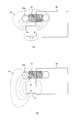
- FIG. 5A schematically shows magnetic force lines 15 generated by the magnet 31.
- the magnetic pole of the magnet 31 is installed in parallel with the rail.
- the magnetic force lines 15 are formed substantially parallel to the direction in which the rail 30 extends.
- the spring 10 is rotated in the circumferential direction so that the hook 10b approaches the one where the density of the magnetic force lines 15 is larger, and as a result, the hook 10b is directed in the vertical direction.
- the magnetic pole of the magnet 32 is installed perpendicular to the rail 30.
- the spring 10 is rotated in the circumferential direction so that the hook 10b approaches the one where the density of the lines of magnetic force 15 is higher, and as a result, the hook 10b faces the vertical direction.
- the position of the magnet 31 is not limited to the magnetic pole being parallel or perpendicular to the rail 30, and may be installed slightly obliquely.
- 6 (A) and 6 (B) show the discharge state of the spring 10 according to the present embodiment.
- the direction of the hook 10b of the spring 10 when coming out from the through hole 30a is various and not constant. Accordingly, the operator needs to grasp the spring 10 by changing the direction of tweezers or the like so that the hook 10b can be sandwiched after looking at the direction of the hook 10b of the spring 10 that comes out, and the working efficiency is poor.
- the hook 10b of the spring 10 faces in the vertical direction.
- the spring 10 stops in a state where the tip portion including the hook 10b comes out from the outlet of the through hole 30a.
- this state is called a state in which the spring 10 is discharged from the through hole 30a. Since the spring 10 is discharged from the through hole 30a and the hook 10b is oriented in the vertical direction, the operator can easily grasp the spring 10 by sandwiching the hook 10b from the left and right with tweezers, for example. Since the springs 10 to be discharged one after another have the hooks 10b aligned in the vertical direction, the working efficiency is improved.
- a pair of sensors 32 are provided in the vicinity of the discharge side end portion 30 b of the rail 30.
- the sensor 32 detects that the spring 10 is at a predetermined position, that is, a state where the spring 10 is discharged from the through hole 30a as shown in FIG.
- the output of the sensor 32 is sent to the control unit 35, and the control unit 35 controls the rotation of the roller 24 and the vibration of the conveyance slope 23 by the driving unit 26.
- the control unit 35 operates the driving unit 26 to rotate the roller 24 and vibrate the conveyance slope 23.
- the plurality of springs 10 arranged in a row on the conveyance slope 23, the conveyance bridge 25, and the rail 30 are sequentially sent in the direction of the discharge side outlet 30b of the rail 30, and the leading spring 10 is shown in FIG.
- the control unit 35 controls the driving unit 26 to stop the rotation of the roller 24 and the vibration of the conveying slope 23.
- the spring 10 is maintained in a state of being discharged from the through hole 30a as shown in FIG. Further, since the rotation of the roller 24 and the vibration of the conveying slope 23 are stopped, when the operation is stopped for some reason, useless power is not used and an energy saving effect is obtained. Thus, every time the operator takes one spring 10, the next spring 10 is discharged from the through hole 30a as shown in FIG. 6A, and automatic supply of the spring 10 is realized.
- annular magnet 31 is used in the above embodiment, the application of the present invention is not limited to this, and a rectangular parallelepiped magnet, for example, may be used.
- the magnet 31 is provided below the through hole 30a at the discharge side end 30b of the rail 30, but the application of the present invention is not limited to this.
- the hook 10b of the spring 10 can be directed in the vertical direction.
- the magnet is provided so that the hook 10b of the spring 10 is in the vertical direction.
- the hook 10b of the spring 10 is supplied from the rail 30 so as to be in the horizontal direction. It may be considered that working efficiency is better.
- the magnet 31 may be provided at either the left or right position of the through hole 30a so that the spring 10 is discharged with the hook 10b facing in the lateral direction.
- a member having hooks made of a magnetic material at both ends is included in the present invention even if it is not a spring.
- the present invention can be used for automatic supply of members with hooks in a production line or the like.
Landscapes
- Engineering & Computer Science (AREA)
- Mechanical Engineering (AREA)
- Feeding Of Articles To Conveyors (AREA)
Abstract
La présente invention se rapporte à un dispositif d'introduction d'éléments (20) destiné à transporter des éléments accrochés (10) comportant des corps magnétiques, les éléments accrochés (10) introduits au moyen d'un mécanisme d'introduction (24) étant transportés par un mécanisme de transport (23, 25, 26, 30) et le mécanisme de transport (23, 25, 26, 30) comportant un rail (30), un dispositif de commande de transport (26) et un aimant (31). Les éléments accrochés (10) transportés par le mécanisme d'introduction (24) sont transportés par l'opération du dispositif de commande de transport (26) et déchargés dans un état dans lequel les orientations des crochets (10b) des éléments accrochés (10) sont alignées par l'action de la force magnétique de l'aimant (10) installé au niveau de la section d'extrémité du rail (30) du côté où les éléments accrochés (10) sont déchargés.
Priority Applications (1)
| Application Number | Priority Date | Filing Date | Title |
|---|---|---|---|
| PCT/JP2013/059858 WO2014162402A1 (fr) | 2013-04-01 | 2013-04-01 | Dispositif d'introduction d'éléments |
Applications Claiming Priority (1)
| Application Number | Priority Date | Filing Date | Title |
|---|---|---|---|
| PCT/JP2013/059858 WO2014162402A1 (fr) | 2013-04-01 | 2013-04-01 | Dispositif d'introduction d'éléments |
Publications (1)
| Publication Number | Publication Date |
|---|---|
| WO2014162402A1 true WO2014162402A1 (fr) | 2014-10-09 |
Family
ID=51657736
Family Applications (1)
| Application Number | Title | Priority Date | Filing Date |
|---|---|---|---|
| PCT/JP2013/059858 Ceased WO2014162402A1 (fr) | 2013-04-01 | 2013-04-01 | Dispositif d'introduction d'éléments |
Country Status (1)
| Country | Link |
|---|---|
| WO (1) | WO2014162402A1 (fr) |
Cited By (1)
| Publication number | Priority date | Publication date | Assignee | Title |
|---|---|---|---|---|
| CN107282470A (zh) * | 2017-05-26 | 2017-10-24 | 惠州市三协精密有限公司 | 磁铁自动上料检测设备 |
Citations (5)
| Publication number | Priority date | Publication date | Assignee | Title |
|---|---|---|---|---|
| JPS4923189B1 (fr) * | 1969-12-25 | 1974-06-13 | ||
| JPS51109580U (fr) * | 1975-02-28 | 1976-09-03 | ||
| JPH02102800U (fr) * | 1989-01-31 | 1990-08-15 | ||
| JPH03133828A (ja) * | 1989-10-19 | 1991-06-07 | Fuji Photo Film Co Ltd | ばね搬送および分離装置 |
| JP2001206532A (ja) * | 2000-01-26 | 2001-07-31 | Tokai Rika Co Ltd | コイルばね供給装置 |
-
2013
- 2013-04-01 WO PCT/JP2013/059858 patent/WO2014162402A1/fr not_active Ceased
Patent Citations (5)
| Publication number | Priority date | Publication date | Assignee | Title |
|---|---|---|---|---|
| JPS4923189B1 (fr) * | 1969-12-25 | 1974-06-13 | ||
| JPS51109580U (fr) * | 1975-02-28 | 1976-09-03 | ||
| JPH02102800U (fr) * | 1989-01-31 | 1990-08-15 | ||
| JPH03133828A (ja) * | 1989-10-19 | 1991-06-07 | Fuji Photo Film Co Ltd | ばね搬送および分離装置 |
| JP2001206532A (ja) * | 2000-01-26 | 2001-07-31 | Tokai Rika Co Ltd | コイルばね供給装置 |
Cited By (2)
| Publication number | Priority date | Publication date | Assignee | Title |
|---|---|---|---|---|
| CN107282470A (zh) * | 2017-05-26 | 2017-10-24 | 惠州市三协精密有限公司 | 磁铁自动上料检测设备 |
| CN107282470B (zh) * | 2017-05-26 | 2023-06-09 | 惠州市三协精密有限公司 | 磁铁自动上料检测设备 |
Similar Documents
| Publication | Publication Date | Title |
|---|---|---|
| US9873572B2 (en) | Part feeder apparatus | |
| CN101784181B (zh) | 电子组件供给器及具有该电子组件供给器的芯片安装器 | |
| US10005188B2 (en) | Parallel link robot, hand for parallel link robot, and parallel link robot system | |
| WO2008110729A3 (fr) | Méthode et système de retassage d'un plateau d'oeufs | |
| JP6107707B2 (ja) | 搬送装置 | |
| KR20160039086A (ko) | 부품 공급장치 | |
| JP2015157661A (ja) | ネジ類供給装置 | |
| CN104191199B (zh) | 一种螺丝分料吹料机构 | |
| US20150223371A1 (en) | Tape feeder and tape setting method | |
| KR20190049227A (ko) | 호스 체결밴드용 밴드 공급장치 | |
| JP6798284B2 (ja) | ネジ供給装置及びネジ供給方法 | |
| JP2015003401A5 (fr) | ||
| JP6328504B2 (ja) | 電子部品供給装置 | |
| CN208063012U (zh) | 转子磁钢的装配进给装置 | |
| JP5910844B2 (ja) | 部品供給装置 | |
| JP2010260653A (ja) | 部品供給装置 | |
| KR101211105B1 (ko) | 자동이송장치 | |
| JP5923827B2 (ja) | ワーク挿入装置およびワーク挿入方法 | |
| JP2017013950A (ja) | ねじ類供給装置 | |
| JP6239362B2 (ja) | 電子部品供給装置 | |
| KR101104926B1 (ko) | 자력형 드럼 타입 철근 공급장치 | |
| JP5938807B2 (ja) | 頭部付き軸状部品の転落構造部 | |
| WO2022009733A1 (fr) | Dispositif de transport pour objet à transporter | |
| JP2008143697A (ja) | ベルト搬送装置 | |
| KR101489847B1 (ko) | 일축 다헤드 로봇 |
Legal Events
| Date | Code | Title | Description |
|---|---|---|---|
| 121 | Ep: the epo has been informed by wipo that ep was designated in this application |
Ref document number: 13880844 Country of ref document: EP Kind code of ref document: A1 |
|
| NENP | Non-entry into the national phase |
Ref country code: DE |
|
| 122 | Ep: pct application non-entry in european phase |
Ref document number: 13880844 Country of ref document: EP Kind code of ref document: A1 |
|
| NENP | Non-entry into the national phase |
Ref country code: JP |