WO2014162548A1 - Sphère d'intégration - Google Patents
Sphère d'intégration Download PDFInfo
- Publication number
- WO2014162548A1 WO2014162548A1 PCT/JP2013/060246 JP2013060246W WO2014162548A1 WO 2014162548 A1 WO2014162548 A1 WO 2014162548A1 JP 2013060246 W JP2013060246 W JP 2013060246W WO 2014162548 A1 WO2014162548 A1 WO 2014162548A1
- Authority
- WO
- WIPO (PCT)
- Prior art keywords
- hole
- light
- integrating sphere
- incident
- light receiving
- Prior art date
- Legal status (The legal status is an assumption and is not a legal conclusion. Google has not performed a legal analysis and makes no representation as to the accuracy of the status listed.)
- Ceased
Links
Images



Classifications
-
- G—PHYSICS
- G01—MEASURING; TESTING
- G01J—MEASUREMENT OF INTENSITY, VELOCITY, SPECTRAL CONTENT, POLARISATION, PHASE OR PULSE CHARACTERISTICS OF INFRARED, VISIBLE OR ULTRAVIOLET LIGHT; COLORIMETRY; RADIATION PYROMETRY
- G01J3/00—Spectrometry; Spectrophotometry; Monochromators; Measuring colours
- G01J3/02—Details
- G01J3/0205—Optical elements not provided otherwise, e.g. optical manifolds, diffusers, windows
- G01J3/0254—Spectrometers, other than colorimeters, making use of an integrating sphere
-
- G—PHYSICS
- G01—MEASURING; TESTING
- G01J—MEASUREMENT OF INTENSITY, VELOCITY, SPECTRAL CONTENT, POLARISATION, PHASE OR PULSE CHARACTERISTICS OF INFRARED, VISIBLE OR ULTRAVIOLET LIGHT; COLORIMETRY; RADIATION PYROMETRY
- G01J1/00—Photometry, e.g. photographic exposure meter
- G01J1/02—Details
- G01J1/04—Optical or mechanical part supplementary adjustable parts
- G01J2001/0481—Preset integrating sphere or cavity
Definitions
- the present invention relates to an integrating sphere used for measuring the characteristics of light.
- Patent Document 1 discloses a colorimeter technique.
- Patent Document 1 does not describe a configuration in which a light receiving unit that measures the amount of light and a wavelength measuring unit that measures the wavelength are provided.
- a through hole is provided in the integrating sphere for each of the light receiving unit that measures the normal amount of light and the wavelength measuring unit that measures the wavelength. It is usual to provide it.
- light that has entered the through hole for the light receiving unit that measures the amount of light and the wavelength measuring unit that measures the wavelength is not incident on the light receiving unit or the wavelength measuring unit due to reflection or the like, but is emitted again from the through hole. There is a possibility that proper measurement cannot be performed.
- the present invention has been made in view of the above problems, and an example of the purpose thereof is that light incident on a through hole for a light receiving unit for measuring the amount of light and a wavelength measuring unit for measuring the wavelength is received by reflection or the like. It is to provide an integrating sphere that is not incident on the part or the wavelength measuring part and is not emitted again from the through hole.
- the integrating sphere according to the first aspect of the present invention includes an integrating sphere main body having a spherical space therein, a first through hole for guiding measurement target light into the spherical space, and a light receiving unit for receiving the light in the spherical space.
- a second through hole for guiding light to the light source, and a wavelength measuring unit for measuring the wavelength of light in addition to the light receiving unit is disposed in the second through hole.
- the integrating sphere according to the second aspect of the present invention includes an integrating sphere main body having a spherical space therein, a first through hole for guiding measurement target light into the spherical space, and a light receiving unit for receiving the light in the spherical space.
- a second through hole for guiding light to the side, and the side surface of the second through hole is formed so as to regularly reflect the incident light. It is formed in a truncated cone shape larger than the surface on the main body side.
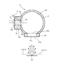
- FIG. 1 is an explanatory diagram of a first embodiment of the present invention.
- FIG. 2 is an explanatory diagram for explaining the function of the integrating sphere 2.
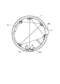
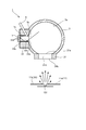
- FIG. 3 is an explanatory diagram of a comparative example.
- the integrating sphere 2 has an integrating sphere body 3, a first through hole portion 31, and a second through hole portion 33.
- the integrating sphere main body 3 has a spherical hollow space.
- the integrating sphere body 3 is formed so that the integrating sphere inner surface 3a, which is the surface on the hollow space side, diffusely reflects (diffuse reflection).
- the hollow space formed by the integrating sphere inner surface 3a of the integrating sphere main body 3 needs to be spherical, but the external shape does not necessarily have to be a sphere.
- a first through hole portion 31 and a second through hole portion 33 are connected to the integrating sphere body 3.
- a cylindrical hollow space is formed in the first through hole portion 31.
- a first through hole 31 c is formed that penetrates from the outside of the first through hole portion 31 to the hollow space of the integrating sphere main body 3.
- the integrating sphere 2 receives the light to be measured through the first through hole 31c of the first through hole 31.
- this 1st through-hole part 31 is a cylindrical shape in this embodiment, it may be prismatic shape (triangular prism, quadrangular prism, pentagonal prism, or more prismatic shapes).
- a cylindrical outer surface formed by the first through holes 31c is referred to as a first outer surface 31b.
- the cylindrical inner surface (integral sphere body 3 side) formed by the first through hole 31c is referred to as a first inner surface 31a.
- a cylindrical hollow space is formed in the second through-hole portion 33.
- a second through hole 33 c is formed that penetrates from the outside of the second through hole portion 33 to the hollow space of the integrating sphere main body 3.
- the integrating sphere 2 outputs the light to be measured through the second through hole 33c of the second through hole 33.
- the light passing through the second through-hole portion 33 is obtained after the light passing through the first through-hole portion 31 is diffusely reflected at the integrating sphere inner surface 3a at least once. The reason for this will be described later in detail.
- the second through-hole portion 33 has a cylindrical shape in this embodiment, but may have a prismatic shape (triangular prism, quadrangular prism, pentagonal prism, or more prismatic shapes).
- a cylindrical outer surface formed by the second through hole 33c is referred to as a second outer surface 33b.
- a cylindrical inner surface (integral sphere body 3 side) formed by the second through hole 33c is referred to as a second inner surface 33a.
- the light receiving unit 7 and the wavelength measuring unit 9 are disposed in the second through hole 33c.
- the light receiving unit 7 is used to measure the amount of light after being diffusely reflected by the integrating sphere body 3.
- a photodetector may be used for the light receiving unit 7.
- a CCD or the like may be used.
- the wavelength measuring unit 9 is used to measure the wavelength of light after being diffusely reflected by the integrating sphere body 3.
- the wavelength measuring unit 9 allows light to enter from the front end surface of the optical fiber, guide the light through the optical fiber, guide it to the wavelength measuring device, and actually measure the wavelength with the wavelength measuring device. good.
- a light guide member may be further used at the tip of the optical fiber so that the light guide member first guides the light to the optical fiber and then guides it to the wavelength measuring device.
- a member that reflects the inner surface of the cylindrical member may be used, or a member (for example, glass) that reflects the extended inner surface may be used.
- the light guide member may be formed of a member that reflects the surface of a cylindrical or prismatic side surface.
- the incident surface 9a of the wavelength measuring unit 9 is formed so as to protrude into the second through hole 33c.
- the wavelength measuring unit 9 passes through the second through hole 33.
- the angle between the light guide direction of the wavelength measuring unit 9 and the direction of the central axis of the second through hole 33c on the light receiving unit 7 side is ⁇ 1
- the configuration is such that ⁇ 1 ⁇ 90 °.
- the wavelength measuring unit 9 can more smoothly guide light to a part to be actually measured such as a spectroscope.
- the integrating sphere 2 outputs diffused light (emitted from the second through hole 33c) by repeating diffuse reflection of the incident light (incident from the first through hole 31c). That is, the integrating sphere 2 can measure light in which the polarization, light distribution, wavelength, and the like of light in the direction of the measurement object 101 (for example, LED) are averaged.
- equation is materialized about the light quantity output with respect to the light quantity input at this time.
- Output port area (second outer surface 33b of second through hole 33c) / total surface area inside integrating sphere ( (in the case of FIG. 1) 3a + 31a + 33a)
- the tip of the probe 11 contacts the electrode of the measurement object 101 (for example, LED).
- the probe 11 is used for supplying power to the measurement object 101 to emit light.
- the probe 11 is not essential when the measurement object 101 does not require the probe 11 or the like.
- the measurement object 101 may be separated from the first through hole 31c as shown in FIG. Furthermore, the measurement object 101 may be disposed inside the first through hole 31c.
- FIG. 3A is a side cross-sectional view that is the same as FIG.
- FIG. 3B is a cross-sectional view taken along the line BB in FIG.
- a second through hole 33c for the light receiving unit 7 is formed as shown in FIG.
- a third through hole 35c for the wavelength measuring unit 9 is formed.
- the second through hole 33c and the third through hole 35c are formed at different positions, the light incident on the light receiving unit 7 and the light incident on the wavelength measuring unit 9 have different characteristics. There is a possibility that.
- the second through hole 33c and the third through hole 35c are provided separately, the light incident on the integrating sphere 2 is dispersed, so that the light incident on the light receiving unit 7 and the wavelength measuring unit 9 The amount will decrease.
- the light receiving unit 7 and the wavelength measuring unit 9 are formed in the same second through hole 33c, the light receiving unit 7 and the wavelength measuring unit 9 have the same characteristics. Can be measured.
- the light receiving unit 7 and the wavelength measuring unit 9 are formed in the same second through hole 33c, it is possible to reduce the decrease in the light amount.
- the inner peripheral surfaces (side surfaces) of the first through hole 31c and the second through hole 33c are formed so as to be diffusely reflected.
- FIG. 4 is an explanatory diagram of the second embodiment.
- the light reflected by the incident surface 9a of the wavelength measuring unit 9 returns to the inside of the integrating sphere body 3 from the second inner surface 33a of the second through hole 33c again without entering the light receiving unit 7.
- the incident surface 9a is formed so as to contact the second through hole 33c.
- ⁇ 2 90 °.
- the configuration is such that ⁇ 1 ⁇ 90 °.
- the shape of the second through hole 33c is a shape such as a truncated cone, ⁇ 2 may not be 90 °.
- the wavelength measuring unit 9 may penetrate into the second through hole 33c.
- FIG. 5 is an explanatory diagram of the third embodiment.
- the inner peripheral surface (side surface) of the second through hole 33c is formed so as to be diffusely reflected.
- a regular reflection material 33d for regular reflection is formed on the inner peripheral surface (side surface) of the second through hole. As a result, the light once incident on the second through hole 33c can be more reliably guided to the light receiving unit 7.
- FIG. 6 is an explanatory diagram of the fourth embodiment.
- the shape of the second through hole 33c is a simple columnar shape.
- the shape of the second through hole 33c is a truncated cone shape as shown in FIG. It is said. More specifically, the surface of the truncated cone on the integrating sphere main body 3 side is formed to have a smaller area than the surface of the truncated cone on the light receiving unit 7 side. Since the fourth embodiment has such a truncated cone shape, the light once incident on the second through hole 33 c can be more reliably guided to the light receiving unit 7.
- the inner peripheral surface of the second through hole 33c is formed so as to be regularly reflected.
- the integrating sphere 2 of the present embodiment includes an integrating sphere main body 3 having a spherical space therein, a first through hole 31c for guiding measurement target light into the spherical space, and a light receiving unit 7 for receiving the light in the spherical space. And a second through hole 33c for guiding light to the second through hole 33c.
- a wavelength measuring unit 9 for measuring the wavelength of light is disposed in the second through hole 33c. Since it has such a configuration, light that has entered the through hole for the light receiving unit for measuring the light amount and the wavelength measuring unit for measuring the wavelength does not enter the light receiving unit or the wavelength measuring unit due to reflection or the like. There is an effect that it is possible to provide an integrating sphere that is not emitted again from the hole.
- the second through-hole 33c has a cylindrical shape
- the wavelength measuring unit 9 has an incident surface 9a on which the light of the measurement object 101 is incident, and the incident surface 9a is second from the side surface of the second through-hole 33c. It arrange
- the normal direction of the incident surface 9a is formed to have a predetermined angle with respect to the central axis of the second through hole 33c. Since it has such a structure, it becomes possible to reduce that the light incident on the incident surface 9a is reflected and emitted again from the second through hole 33c.
- the light guide direction of the light incident on the wavelength measuring unit 9 from the incident surface 9a is formed to have a predetermined angle with respect to the central axis of the second through hole 33c. Since it has such a structure, it becomes possible to guide the light of a measuring object more smoothly.
- the normal direction of the incident surface 9a is formed at right angles to the central axis of the second through hole 33c. Since it has such a configuration, it is also possible to provide the wavelength measuring unit 9 without hindering the light guide in the second through hole 33c.
- the side surface of the second through hole 33c is formed so as to regularly reflect incident light. With such a configuration, it is possible to more reliably guide the light once incident on the second through hole 33c to the light receiving unit 7.
- the second through hole 33c is formed in a truncated cone shape having a surface on the light receiving unit side larger than a surface on the integrating sphere main body side. Since it has such a structure, it becomes possible to guide the light once incident on the second through hole 33c to the light receiving unit 7 more reliably.
- An integrating sphere body 3 having a spherical space therein, a first through hole 31c for guiding the measurement target light into the spherical space, and a second through for guiding the light in the spherical space to the light receiving unit 7
- the side surface of the second through hole 33c is formed so as to regularly reflect incident light
- the second through hole 33c has a surface on the light receiving unit 7 side on the surface of the integrating sphere body 3 side. It is formed in a larger truncated cone shape. Since it has such a configuration, light that has entered the through hole for the light receiving unit for measuring the light amount and the wavelength measuring unit for measuring the wavelength does not enter the light receiving unit or the wavelength measuring unit due to reflection or the like. There is an effect that it is possible to provide an integrating sphere that is not emitted again from the hole.
- the integrating sphere inner surface 3a of the integrating sphere 2 is described as diffusely reflecting. However, the integrating sphere inner surface 3a may be regularly reflected.
Landscapes
- Physics & Mathematics (AREA)
- Spectroscopy & Molecular Physics (AREA)
- General Physics & Mathematics (AREA)
- Photometry And Measurement Of Optical Pulse Characteristics (AREA)
- Spectrometry And Color Measurement (AREA)
- Investigating Or Analysing Materials By Optical Means (AREA)
Abstract
La présente invention concerne une sphère d'intégration dans laquelle une lumière incidente sur un trou débouchant, pour une partie réception de lumière servant à mesurer une quantité de lumière et une partie mesure de longueur d'onde servant à mesurer une longueur d'onde, ne peut pas être émise de nouveau à partir du trou débouchant sans être incidente sur la partie réception de lumière ou la partie mesure de longueur d'onde en raison de sa réflexion ou autres. La sphère d'intégration (2) comprend un corps (3) de sphère d'intégration renfermant un espace sphérique, un premier trou débouchant (31c) servant à guider une lumière à mesurer dans l'espace sphérique et un second trou débouchant (33c) servant à guider la lumière dans l'espace sphérique vers une partie réception de lumière (7), une partie mesure de longueur d'onde (9) servant à mesurer la longueur d'onde de la lumière étant située dans le second trou débouchant (33c) en plus de la partie réception de lumière (7).
Priority Applications (2)
| Application Number | Priority Date | Filing Date | Title |
|---|---|---|---|
| JP2015509799A JPWO2014162548A1 (ja) | 2013-04-03 | 2013-04-03 | 積分球 |
| PCT/JP2013/060246 WO2014162548A1 (fr) | 2013-04-03 | 2013-04-03 | Sphère d'intégration |
Applications Claiming Priority (1)
| Application Number | Priority Date | Filing Date | Title |
|---|---|---|---|
| PCT/JP2013/060246 WO2014162548A1 (fr) | 2013-04-03 | 2013-04-03 | Sphère d'intégration |
Publications (1)
| Publication Number | Publication Date |
|---|---|
| WO2014162548A1 true WO2014162548A1 (fr) | 2014-10-09 |
Family
ID=51657880
Family Applications (1)
| Application Number | Title | Priority Date | Filing Date |
|---|---|---|---|
| PCT/JP2013/060246 Ceased WO2014162548A1 (fr) | 2013-04-03 | 2013-04-03 | Sphère d'intégration |
Country Status (2)
| Country | Link |
|---|---|
| JP (1) | JPWO2014162548A1 (fr) |
| WO (1) | WO2014162548A1 (fr) |
Cited By (2)
| Publication number | Priority date | Publication date | Assignee | Title |
|---|---|---|---|---|
| CN109459215A (zh) * | 2018-12-27 | 2019-03-12 | 北京航天长征飞行器研究所 | 用于空间目标远近场光学特性测量的装置 |
| TWI702379B (zh) * | 2015-10-02 | 2020-08-21 | 晶元光電股份有限公司 | 發光裝置之測試設備 |
Citations (3)
| Publication number | Priority date | Publication date | Assignee | Title |
|---|---|---|---|---|
| JPH03162634A (ja) * | 1989-11-20 | 1991-07-12 | Sanyo Electric Co Ltd | 光源の外部量子効率測定方法 |
| JP2002206967A (ja) * | 2001-01-11 | 2002-07-26 | Minolta Co Ltd | 測光装置および測色装置 |
| JP2007198983A (ja) * | 2006-01-27 | 2007-08-09 | Hamamatsu Photonics Kk | 積分球用アダプタ及びこれを備える光検出装置 |
Family Cites Families (4)
| Publication number | Priority date | Publication date | Assignee | Title |
|---|---|---|---|---|
| JPS547820Y2 (fr) * | 1975-02-04 | 1979-04-11 | ||
| JPH03210437A (ja) * | 1989-11-02 | 1991-09-13 | Terumo Corp | 赤外線センサ及びその製造方法 |
| JPWO2012073346A1 (ja) * | 2010-11-30 | 2014-05-19 | パイオニア株式会社 | 発光ダイオード素子用受光モジュール及び発光ダイオード素子用検査装置 |
| JP2012159457A (ja) * | 2011-02-02 | 2012-08-23 | Unitec Co Ltd | 積分球装置及び光測定方法 |
-
2013
- 2013-04-03 JP JP2015509799A patent/JPWO2014162548A1/ja active Pending
- 2013-04-03 WO PCT/JP2013/060246 patent/WO2014162548A1/fr not_active Ceased
Patent Citations (3)
| Publication number | Priority date | Publication date | Assignee | Title |
|---|---|---|---|---|
| JPH03162634A (ja) * | 1989-11-20 | 1991-07-12 | Sanyo Electric Co Ltd | 光源の外部量子効率測定方法 |
| JP2002206967A (ja) * | 2001-01-11 | 2002-07-26 | Minolta Co Ltd | 測光装置および測色装置 |
| JP2007198983A (ja) * | 2006-01-27 | 2007-08-09 | Hamamatsu Photonics Kk | 積分球用アダプタ及びこれを備える光検出装置 |
Cited By (2)
| Publication number | Priority date | Publication date | Assignee | Title |
|---|---|---|---|---|
| TWI702379B (zh) * | 2015-10-02 | 2020-08-21 | 晶元光電股份有限公司 | 發光裝置之測試設備 |
| CN109459215A (zh) * | 2018-12-27 | 2019-03-12 | 北京航天长征飞行器研究所 | 用于空间目标远近场光学特性测量的装置 |
Also Published As
| Publication number | Publication date |
|---|---|
| JPWO2014162548A1 (ja) | 2017-02-16 |
Similar Documents
| Publication | Publication Date | Title |
|---|---|---|
| TWI868688B (zh) | 光學量測裝置以及光學裝置 | |
| US9696141B2 (en) | Method and system for simultaneous measurement of strain and temperature utilizing dual core fiber | |
| JP6185864B2 (ja) | 積分球 | |
| CN109477791A (zh) | 浓度测定装置 | |
| RU2015117776A (ru) | Спектроскопическое измерительное устройство | |
| KR20230025483A (ko) | 광학 장치, 색채 휘도계 및 색채계 | |
| KR20130012588A (ko) | 측정용 광학계 및 그것을 사용한 휘도계, 색채 휘도계 및 색채계 | |
| CN107567594A (zh) | 用于检验能借助电磁辐射激励的样品的装置以及分束器 | |
| JP6199374B2 (ja) | 光特性測定装置 | |
| JPWO2014162548A1 (ja) | 積分球 | |
| US20150147030A1 (en) | Optical coupling lens | |
| CN103852831A (zh) | 透镜单元及光纤耦合连接器 | |
| JP7415923B2 (ja) | 測光装置 | |
| JP2017102107A (ja) | 光ファイバ装置及びセンサシステム | |
| JP2006145373A (ja) | マルチアングル測色計、照明装置及び受光装置 | |
| KR102676195B1 (ko) | 광섬유 일체형 온도 센서 및 이를 이용한 온도 측정 장치 | |
| JP2007198883A (ja) | 光ファイバープローブによる分光測定装置 | |
| US20170146398A1 (en) | Spectrometer and integrating sphere | |
| CN105510296B (zh) | 便携式消荧光拉曼光谱检测系统 | |
| CN207894587U (zh) | 分光辐射谱仪检测头结构 | |
| JP2018128277A (ja) | プローブ及び光学測定器 | |
| EP3332277A1 (fr) | Échantillonneur de faisceau anamorphique réducteur de rétrodiffusion | |
| JP2010197224A (ja) | 分光器 | |
| CN114894122B (zh) | 垂直度测量探头及测量装置 | |
| JP2015161633A (ja) | 光学系および光沢計 |
Legal Events
| Date | Code | Title | Description |
|---|---|---|---|
| 121 | Ep: the epo has been informed by wipo that ep was designated in this application |
Ref document number: 13881161 Country of ref document: EP Kind code of ref document: A1 |
|
| ENP | Entry into the national phase |
Ref document number: 2015509799 Country of ref document: JP Kind code of ref document: A |
|
| NENP | Non-entry into the national phase |
Ref country code: DE |
|
| 122 | Ep: pct application non-entry in european phase |
Ref document number: 13881161 Country of ref document: EP Kind code of ref document: A1 |