WO2014167599A1 - Appareil de coulée continue à étirage par le haut et procédé de coulée continue à étirage vers le haut - Google Patents
Appareil de coulée continue à étirage par le haut et procédé de coulée continue à étirage vers le haut Download PDFInfo
- Publication number
- WO2014167599A1 WO2014167599A1 PCT/JP2013/002454 JP2013002454W WO2014167599A1 WO 2014167599 A1 WO2014167599 A1 WO 2014167599A1 JP 2013002454 W JP2013002454 W JP 2013002454W WO 2014167599 A1 WO2014167599 A1 WO 2014167599A1
- Authority
- WO
- WIPO (PCT)
- Prior art keywords
- molten metal
- defining member
- shape defining
- shape
- continuous casting
- Prior art date
- Legal status (The legal status is an assumption and is not a legal conclusion. Google has not performed a legal analysis and makes no representation as to the accuracy of the status listed.)
- Ceased
Links
Images


Classifications
-
- B—PERFORMING OPERATIONS; TRANSPORTING
- B22—CASTING; POWDER METALLURGY
- B22D—CASTING OF METALS; CASTING OF OTHER SUBSTANCES BY THE SAME PROCESSES OR DEVICES
- B22D11/00—Continuous casting of metals, i.e. casting in indefinite lengths
- B22D11/14—Plants for continuous casting
- B22D11/145—Plants for continuous casting for upward casting
-
- B—PERFORMING OPERATIONS; TRANSPORTING
- B22—CASTING; POWDER METALLURGY
- B22D—CASTING OF METALS; CASTING OF OTHER SUBSTANCES BY THE SAME PROCESSES OR DEVICES
- B22D11/00—Continuous casting of metals, i.e. casting in indefinite lengths
- B22D11/08—Accessories for starting the casting procedure
-
- B—PERFORMING OPERATIONS; TRANSPORTING
- B22—CASTING; POWDER METALLURGY
- B22D—CASTING OF METALS; CASTING OF OTHER SUBSTANCES BY THE SAME PROCESSES OR DEVICES
- B22D11/00—Continuous casting of metals, i.e. casting in indefinite lengths
- B22D11/12—Accessories for subsequent treating or working cast stock in situ
- B22D11/124—Accessories for subsequent treating or working cast stock in situ for cooling
- B22D11/1246—Nozzles; Spray heads
-
- B—PERFORMING OPERATIONS; TRANSPORTING
- B22—CASTING; POWDER METALLURGY
- B22D—CASTING OF METALS; CASTING OF OTHER SUBSTANCES BY THE SAME PROCESSES OR DEVICES
- B22D11/00—Continuous casting of metals, i.e. casting in indefinite lengths
- B22D11/16—Controlling or regulating processes or operations
- B22D11/22—Controlling or regulating processes or operations for cooling cast stock or mould
Definitions
- the present invention relates to a pull-up type continuous casting apparatus and a pull-up type continuous casting method.
- Patent Document 1 proposes a free casting method as an innovative pull-up type continuous casting method that does not require a mold.
- the starter is immersed in the surface of the molten metal (molten metal) (that is, the molten metal surface) (that is, the molten metal surface)
- the molten metal follows the starter by the surface film or surface tension of the molten metal.
- a casting having a desired cross-sectional shape can be continuously cast by deriving and cooling the molten metal through a shape determining member installed in the vicinity of the molten metal surface.
- the shape in the longitudinal direction is defined along with the cross-sectional shape by the mold.
- the cast casting since the solidified metal (that is, the casting) needs to pass through the mold, the cast casting has a shape extending linearly in the longitudinal direction.
- the shape defining member in the free casting method defines only the cross-sectional shape of the casting, and does not define the shape in the longitudinal direction.
- regulation member can move to the direction (namely, horizontal direction) parallel to a molten metal surface, the casting in which the shape of a longitudinal direction is various is obtained.
- Patent Document 1 discloses a hollow casting (that is, a pipe) that is formed in a zigzag shape or a spiral shape instead of being linear in the longitudinal direction.
- the inventor has found the following problems.
- the molten metal led out through the shape defining member is cooled by a cooling gas.
- the molten gas is indirectly cooled by spraying a cooling gas onto the casting immediately after solidification.
- the cooling gas flow rate is increased, the casting speed can be increased and the productivity can be improved.
- the flow rate of the cooling gas is increased, there is a problem that the molten metal derived from the shape determining member is swung by the cooling gas and the dimensional accuracy and surface quality of the casting deteriorate.
- This invention is made in view of the above, Comprising: It aims at providing the pull-up-type continuous casting apparatus and pull-up-type continuous casting method which are excellent in the dimensional accuracy and surface quality of a casting, and also excellent in productivity. .
- the up-drawing continuous casting apparatus is as follows.
- a shape determining member that is installed in the vicinity of the surface of the molten metal held in the holding furnace and that defines a cross-sectional shape of a casting to be cast by a molten metal passage portion through which the molten metal passes,
- a nozzle that blows cooling gas against the casting formed by solidification of the molten metal that has passed through the molten metal passage part
- the shape defining member is Cooling means for cooling the molten metal on the outlet side of the molten metal passage part;
- Heat retaining means for retaining the molten metal on the inlet side of the molten metal passage part,
- An end surface shape of the molten metal passage portion is curved along a surface shape of the molten metal pulled up from the molten metal surface.
- the heat retaining means includes a heat insulating film formed on the lower surface of the shape defining member and a heater formed on the inlet side of the molten metal passage portion.
- An up-drawing continuous casting apparatus is as follows.
- a shape determining member that is installed in the vicinity of the molten metal surface of the molten metal held in the holding furnace and that defines the cross-sectional shape of a casting to be cast by passing the molten metal,
- a nozzle that blows cooling gas against the casting formed by solidification of the molten metal that has passed through the shape defining member,
- the shape defining member is A lower shape defining member in contact with the molten metal held in the holding furnace;
- An upper shape defining member provided above the lower shape memory member and having cooling means for cooling the molten metal passing therethrough.
- the cooling means is a flow path for flowing a refrigerant.
- the refrigerant is a gas.
- the up-drawing continuous casting method is as follows. Passing the molten metal held in the holding furnace through the molten metal passage portion of the shape defining member that defines the cross-sectional shape of the casting to be cast, and pulling up; Spraying a cooling gas to the casting formed from the molten metal that has passed through the molten metal passage,
- the shape defining member is Cooling means for cooling the molten metal on the outlet side of the molten metal passage part; Heat retaining means for retaining the molten metal on the inlet side of the molten metal passage part, An end surface shape of the molten metal passage portion is curved along a surface shape of the molten metal pulled up from the molten metal surface.
- the heat retaining means it is preferable to use a heat insulating film formed on the lower surface of the shape defining member or a heater formed on the inlet side of the molten metal passage portion.
- the up-drawing continuous casting method is as follows. Passing the molten metal held in the holding furnace through a shape defining member that defines the cross-sectional shape of the casting to be cast, and pulling up; Spraying a cooling gas to the casting formed from the molten metal that has passed through the shape defining member,
- the shape defining member is A lower shape defining member in contact with the molten metal held in the holding furnace; An upper shape defining member provided above the lower shape memory member, The upper shape defining member includes a cooling means for cooling the molten metal passing therethrough.
- the cooling means it is preferable to use a flow path through which a refrigerant flows.
- the refrigerant is a gas.
- the refrigerant and the cooling gas are the same gas in order to simplify the facility.
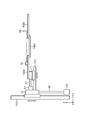
- FIG. 1 is a schematic cross-sectional view of a free casting apparatus according to Embodiment 1.
- FIG. 3 is a plan view of a shape defining member 102 according to Embodiment 1.
- FIG. 3 is a schematic cross-sectional view of a free casting apparatus according to a comparative example of Embodiment 1.
- FIG. 6 is a plan view of a shape defining member 102 according to a modification of the first embodiment.
- FIG. 6 is a side view of a shape defining member 102 according to a modification of the first embodiment.
- FIG. 6 is a schematic cross-sectional view of a free casting apparatus according to Embodiment 2.
- FIG. 6 is a schematic cross-sectional view of a free casting apparatus according to Embodiment 3.
- FIG. 1 is a schematic cross-sectional view of a free casting apparatus according to Embodiment 1.
- the free casting apparatus according to Embodiment 1 includes a molten metal holding furnace 101, a shape defining member 102, a support rod 104, an actuator 105, a cooling gas nozzle 106, and a pulling machine 108.
- the xy plane in FIG. 1 constitutes a horizontal plane, and the z-axis direction is the vertical direction. More specifically, the positive direction of the z axis is vertically upward.
- the molten metal holding furnace 101 accommodates a molten metal M1 such as aluminum or an alloy thereof and holds it at a predetermined temperature.
- a molten metal M1 such as aluminum or an alloy thereof
- the surface of the molten metal M1 decreases as the casting progresses.
- the molten metal may be replenished to the molten metal holding furnace 101 at any time during casting to keep the molten metal surface constant.
- the molten metal M1 may be another metal or alloy other than aluminum.
- the shape defining member 102 is made of, for example, stainless steel and is disposed near the hot water surface. In the example of FIG. 1, the main surface (lower surface) on the lower side of the shape defining member 102 is disposed so as to contact the molten metal surface.
- the shape defining member 102 defines the cross-sectional shape of the casting M3 to be cast, and prevents the oxide film formed on the surface of the molten metal M1 and foreign matters floating on the surface of the molten metal M1 from entering the casting M3.
- the casting M3 shown in FIG. 1 is a solid casting in which the shape of a horizontal cross section (hereinafter referred to as a transverse cross section) is a plate shape.
- FIG. 2 is a plan view of the shape defining member 102 according to the first embodiment.
- the cross-sectional view of the shape determining member 102 in FIG. 1 corresponds to the II cross-sectional view in FIG.
- the shape defining member 102 has, for example, a rectangular planar shape, and has a rectangular opening portion (a molten metal passage portion 103) having a thickness t ⁇ b> 1 ⁇ a width w ⁇ b> 1 for allowing the molten metal to pass through a central portion.
- a molten metal passage portion 103 having a thickness t ⁇ b> 1 ⁇ a width w ⁇ b> 1 for allowing the molten metal to pass through a central portion.
- the xyz coordinates in FIG. 2 coincide with those in FIG.
- the molten metal M ⁇ b> 1 is pulled up following the casting M ⁇ b> 3 by its surface film and surface tension, and passes through the molten metal passage portion 103 of the shape determining member 102. That is, when the molten metal M1 passes through the molten metal passage portion 103 of the shape defining member 102, an external force is applied from the shape defining member 102 to the molten metal M1, and the cross-sectional shape of the casting M3 is defined.
- the molten metal pulled up from the molten metal surface following the casting M3 due to the surface film or surface tension of the molten metal is referred to as retained molten metal M2. Further, the boundary between the casting M3 and the retained molten metal M2 is a solidification interface SIF.
- FIG. 3 is a schematic cross-sectional view of a free casting apparatus according to a comparative example of the first embodiment.
- the shape defining member 102 according to the first embodiment is thicker than the shape defining member 2 according to the comparative example, and covers substantially the entire surface of the retained molten metal M2. Therefore, it is possible to suppress the peristalsis of the surface of the retained molten metal M2 due to the cooling gas blown from the cooling gas nozzle 106 to the casting M3. As a result, the dimensional accuracy and surface quality of the casting can be improved.
- the casting speed can be increased and the productivity can be improved by increasing the flow rate of the cooling gas as compared with the conventional method.
- the degree of freedom of the shape of the casting M3 in the longitudinal direction is reduced, and the casting M3 extends on a straight line.
- the lower opening (inlet) and the upper opening (outlet) of the molten metal passage portion 3 have the same size, and the end surface of the molten metal passage portion 3 is relative to the main surface. Vertical and flat.
- the inlet of the molten metal passage portion 103 is slightly larger than the outlet, and the end surface of the molten metal passage portion 103 is inclined with respect to the main surface.
- the end surface of the molten metal passage portion 103 is curved in a convex shape along the surface shape of the retained molten metal M2 pulled up from the molten metal surface.
- components other than the shape defining member 2 in the free casting apparatus according to the comparative example are the same as those in the free casting apparatus according to the first embodiment, description thereof is omitted.
- the shape defining member 102 includes a cooling means on the upper side inside. Specifically, the shape defining member 102 includes a refrigerant flow path 2 a as a cooling means in the vicinity of the upper side (outlet side) of the molten metal passage portion 103. Therefore, the retained molten metal M2 in the vicinity of the outlet of the molten metal passage portion 103 passing through the shape defining member 102 can be effectively cooled, and the position of the solidification interface SIF can be maintained near the shape defining member 102.
- the refrigerant flow path 2a is formed in an annular shape so as to surround the molten metal passage portion 103, for example.
- the refrigerant flowing through the refrigerant flow path 2a it is preferable from the viewpoint of safety to use the same cooling gas as the cooling gas blown from the cooling gas nozzle 106 to the casting M3.
- the cooling gas flowing through the cooling gas nozzle 106 and the refrigerant flow path 2a be the same gas because the equipment can be simplified.
- the shape defining member 102 is provided with a heat retaining means on the lower side in order to suppress a temperature drop of the molten metal M1 due to the shape defining member 102.
- the shape determining member 102 includes a heat insulating film 2b made of a coating agent having heat insulating property applied to the lower surface as a heat retaining means.
- a vermiculite coating material can be used as the coating agent.
- the vermiculite coating material is a coating material in which refractory fine particles such as silicon oxide (SiO 2 ), iron oxide (Fe 2 O 3 ), and aluminum oxide (Al 2 O 3 ) are suspended in water.
- the heat insulation film 2b can keep the molten metal M1 in the vicinity of the inlet of the molten metal passage portion 103 passing through the shape defining member 102 from now on. Therefore, the temperature drop of the molten metal M1 can be suppressed, and the dimensional accuracy and surface quality of the casting can be improved.
- the support rod 104 supports the shape defining member 102.
- a support rod 104 is connected to the actuator 105.
- the shape defining member 102 can be moved in the vertical direction (vertical direction) and the horizontal direction by the actuator 105 via the support rod 104. With such a configuration, the shape determining member 102 can be moved downward as the molten metal surface is lowered due to the progress of casting. Further, since the shape defining member 102 can be moved in the horizontal direction, the shape of the casting M3 in the longitudinal direction can be changed.
- the cooling gas nozzle (cooling unit) 106 is a cooling unit that blows cooling gas (air, nitrogen, argon, etc.) supplied from a cooling gas supply unit (not shown) onto the casting M3 to cool it. Increasing the flow rate of the cooling gas can lower the position of the solidification interface, and decreasing the flow rate of the cooling gas can increase the position of the solidification interface. Although not shown, the cooling gas nozzle (cooling unit) 106 can also move in the horizontal direction and the vertical direction in accordance with the movement of the shape defining member 102.
- the casting M3 While the casting M3 is pulled up by the pulling machine 108 connected to the starter ST and the casting M3 is cooled by the cooling gas, the retained molten metal M2 near the solidification interface is sequentially solidified to form the casting M3.
- the pulling speed by the pulling machine 108 is increased, the position of the solidification interface can be increased, and when the pulling speed is decreased, the position of the solidification interface can be decreased.
- the free casting method according to Embodiment 1 will be described with reference to FIG. First, the starter ST is lowered, and the tip of the starter ST is immersed in the molten metal M1 through the molten metal passage portion 103 of the shape defining member 102.
- start-up of the starter ST is started at a predetermined speed.
- the retained molten metal M2 pulled up from the molten metal surface following the starter ST is formed by the surface film or surface tension.
- the retained molten metal M ⁇ b> 2 is formed in the molten metal passage portion 103 of the shape defining member 102. That is, the shape defining member 102 imparts a shape to the retained molten metal M2.
- the starter ST is cooled by the cooling gas blown from the cooling gas nozzle 106, the retained molten metal M2 is solidified in order from the upper side to the lower side, and the casting M3 grows. In this way, the casting M3 can be continuously cast.
- the shape defining member 102 covers substantially the entire surface of the retained molten metal M2, so that the surface of the retained molten metal M2 caused by cooling gas can be prevented from swinging. .
- the dimensional accuracy and surface quality of the casting can be improved.
- the casting speed can be increased and the productivity can be improved.
- the shape defining member 102 includes a refrigerant flow path 2 a as a cooling means for cooling the molten metal near the outlet of the molten metal passage portion 103 passing through the shape defining member 102. Therefore, the retained molten metal M2 that has passed through the shape defining member 102 can be effectively cooled, and the position of the solidification interface SIF can be maintained near the shape defining member 102.
- the shape defining member 102 includes a heat insulating film 2b as a heat retaining means for retaining the molten metal M1 in the vicinity of the inlet of the molten metal passage portion 103 that passes through the shape defining member 102. Therefore, the temperature reduction of the molten metal M1 by the shape defining member 102 can be suppressed, and the dimensional accuracy and surface quality of the casting can be improved.
- FIG. 4 is a plan view of a shape defining member 102 according to a modification of the first embodiment.
- FIG. 5 is a side view of the shape defining member 102 according to a modification of the first embodiment. Note that the xyz coordinates in FIGS. 4 and 5 also coincide with those in FIG.
- the shape defining member 102 according to Embodiment 1 shown in FIG. 2 is composed of one plate, the thickness t1 and the width w1 of the molten metal passage portion 103 are fixed.
- the shape defining member 102 according to the modification of the first embodiment includes four rectangular shape defining plates 102a, 102b, 102c, and 102d as shown in FIG. That is, the shape defining member 102 according to the modification of the first embodiment is divided into a plurality of parts. With such a configuration, the thickness t1 and the width w1 of the molten metal passage portion 103 can be changed. Further, the four rectangular shape defining plates 102a, 102b, 102c, and 102d can move in the z-axis direction in synchronization.
- the shape defining plates 102a and 102b are arranged to face each other in the x-axis direction. Further, as shown in FIG. 5, the shape defining plates 102a and 102b are arranged at the same height in the z-axis direction. The distance between the shape defining plates 102a and 102b defines the width w1 of the molten metal passage portion 103. Since the shape defining plates 102a and 102b can move independently in the x-axis direction, the width w1 can be changed.
- a laser displacement meter S1 may be provided on the shape defining plate 102a and a laser reflecting plate S2 may be provided on the shape defining plate 102b as shown in FIGS. .
- the shape defining plates 102c and 102d are arranged to face each other in the y-axis direction. Further, the shape defining plates 102c and 102c are arranged at the same height in the z-axis direction. The distance between the shape defining plates 102c and 102d defines the thickness t1 of the molten metal passage portion 103. Since the shape defining plates 102c and 102d are independently movable in the y-axis direction, the thickness t1 can be changed.
- the shape defining plates 102a and 102b are disposed so as to contact the upper side of the shape defining plates 102c and 102d.
- the drive mechanism of the shape defining plate 102a will be described with reference to FIGS.
- the drive mechanism for the shape defining plate 102a includes slide tables T1, T2, linear guides G11, G12, G21, G22, actuators A1, A2, and rods R1, R2.
- the shape defining plates 102b, 102c, and 102d are provided with a drive mechanism similarly to the shape defining plate 102a, but are omitted in FIGS.
- the shape defining plate 102a is placed and fixed on a slide table T1 that can slide in the x-axis direction.
- the slide table T1 is slidably mounted on a pair of linear guides G11 and G12 extending in parallel with the x-axis direction.
- the slide table T1 is connected to a rod R1 extending from the actuator A1 in the x-axis direction.
- the linear guides G11 and G12 and the actuator A1 are mounted and fixed on a slide table T2 that can slide in the z-axis direction.
- the slide table T2 is slidably placed on a pair of linear guides G21 and G22 extending in parallel with the z-axis direction.
- the slide table T2 is connected to a rod R2 extending in the z-axis direction from the actuator A2.
- the linear guides G21 and G22 and the actuator A2 are fixed to a horizontal floor surface or a pedestal (not shown). With the above configuration, the shape defining plate 102a can slide in the z-axis direction.
- the actuators A1 and A2 can include hydraulic cylinders, air cylinders, motors, and the like.
- FIG. 6 is a schematic cross-sectional view of the free casting apparatus according to the second embodiment. Note that the xyz coordinates in FIG. 6 also match those in FIG.
- the shape defining member 102 includes the heat insulating film 2b as a heat retaining means on the lower side.
- the shape defining member 202 includes a heater 22b as a heat retaining means on the lower side thereof.
- the shape defining member 202 includes a heater 22b as a heat retaining means for retaining the molten metal M1 in the vicinity of the inlet of the molten metal passage portion 103. Therefore, the temperature reduction of the molten metal M1 by the shape defining member 202 can be suppressed, and the dimensional accuracy and surface quality of the casting can be improved.
- the heater 22b is formed in an annular shape so as to surround the molten metal passage portion 103, for example.
- the shape defining member 102 according to the second embodiment also covers substantially the entire surface of the retained molten metal M2, similarly to the shape defining member 102 according to the first embodiment. Therefore, the surface of the retained molten metal M2 due to the cooling gas can be prevented from swinging. As a result, the dimensional accuracy and surface quality of the casting can be improved. On the other hand, by increasing the flow rate of the cooling gas as compared with the prior art, the casting speed can be increased and the productivity can be improved.
- the shape defining member 202 according to the second embodiment is also provided with a refrigerant flow path 2a as a cooling means in the vicinity of the upper side (outlet side) of the molten metal passage portion 103, similarly to the shape defining member 102 according to the first embodiment. ing. Therefore, the retained molten metal M ⁇ b> 2 that has passed through the shape defining member 202 can be effectively cooled, and the position of the solidification interface SIF can be maintained near the shape defining member 202. Since other configurations are the same as those of the first embodiment, the description thereof is omitted.
- FIG. 7 is a schematic cross-sectional view of the free casting apparatus according to the third embodiment. Note that the xyz coordinates in FIG. 7 also coincide with those in FIG.
- the shape defining member 302 includes the upper shape defining member 21 disposed on the upper side and the lower shape defining member 22 disposed on the lower side. In other words, the shape defining member 302 is divided into the upper shape defining member 21 and the lower shape defining member 22 in the vertical direction.
- the shape defining member 102 according to Embodiment 1 was provided with a heat insulating film 2b as a heat retaining means on the lower side thereof.
- the lower shape defining member 22 in contact with the molten metal M1 is divided from the upper shape defining member 21 and is thermally insulated. Therefore, even if the lower shape defining member 22 is not provided with a heat retaining means, the temperature drop of the molten metal M1 can be suppressed, and the dimensional accuracy and surface quality of the casting can be improved.
- the lower shape defining member 22 may include heat insulation means such as the heat insulating film 2b according to the first embodiment and the heater 22b according to the second embodiment.
- the upper shape defining member 21 covers substantially the entire surface of the retained molten metal M2, the surface shape of the retained molten metal M2 due to the cooling gas can be suppressed. As a result, the dimensional accuracy and surface quality of the casting can be improved. On the other hand, by increasing the flow rate of the cooling gas as compared with the prior art, the casting speed can be increased and the productivity can be improved.
- the upper shape defining member 21 also includes a refrigerant flow path 2 a as a cooling means in the vicinity of the molten metal passage portion 103. Therefore, the retained molten metal M ⁇ b> 2 that has passed through the shape defining member 302 can be effectively cooled, and the position of the solidification interface SIF can be maintained near the shape defining member 302. Since other configurations are the same as those of the first embodiment, description thereof is omitted.
Landscapes
- Engineering & Computer Science (AREA)
- Mechanical Engineering (AREA)
- Continuous Casting (AREA)
- Mold Materials And Core Materials (AREA)
Abstract
Priority Applications (4)
| Application Number | Priority Date | Filing Date | Title |
|---|---|---|---|
| PCT/JP2013/002454 WO2014167599A1 (fr) | 2013-04-10 | 2013-04-10 | Appareil de coulée continue à étirage par le haut et procédé de coulée continue à étirage vers le haut |
| US14/777,937 US20160101465A1 (en) | 2013-04-10 | 2013-04-10 | Pulling-up-type continuous casting apparatus and pulling-up-type continuous casting method |
| JP2015510949A JP6020712B2 (ja) | 2013-04-10 | 2013-04-10 | 引上式連続鋳造装置及び引上式連続鋳造方法 |
| CN201380075499.6A CN105102153A (zh) | 2013-04-10 | 2013-04-10 | 上引式连续铸造装置以及上引式连续铸造方法 |
Applications Claiming Priority (1)
| Application Number | Priority Date | Filing Date | Title |
|---|---|---|---|
| PCT/JP2013/002454 WO2014167599A1 (fr) | 2013-04-10 | 2013-04-10 | Appareil de coulée continue à étirage par le haut et procédé de coulée continue à étirage vers le haut |
Publications (1)
| Publication Number | Publication Date |
|---|---|
| WO2014167599A1 true WO2014167599A1 (fr) | 2014-10-16 |
Family
ID=51689037
Family Applications (1)
| Application Number | Title | Priority Date | Filing Date |
|---|---|---|---|
| PCT/JP2013/002454 Ceased WO2014167599A1 (fr) | 2013-04-10 | 2013-04-10 | Appareil de coulée continue à étirage par le haut et procédé de coulée continue à étirage vers le haut |
Country Status (4)
| Country | Link |
|---|---|
| US (1) | US20160101465A1 (fr) |
| JP (1) | JP6020712B2 (fr) |
| CN (1) | CN105102153A (fr) |
| WO (1) | WO2014167599A1 (fr) |
Citations (3)
| Publication number | Priority date | Publication date | Assignee | Title |
|---|---|---|---|---|
| JPS63199049A (ja) * | 1987-02-13 | 1988-08-17 | Sumitomo Electric Ind Ltd | 連続結晶成長方法 |
| JPH02205232A (ja) * | 1989-02-01 | 1990-08-15 | Natl Res Inst For Metals | 引上げ連続鋳造法とその装置 |
| JP2012061518A (ja) * | 2010-09-17 | 2012-03-29 | Toyota Central R&D Labs Inc | 自由鋳造方法、自由鋳造装置および鋳物 |
Family Cites Families (3)
| Publication number | Priority date | Publication date | Assignee | Title |
|---|---|---|---|---|
| SE445181B (sv) * | 1982-12-15 | 1986-06-09 | Nippon Light Metal Co | Sett vid kontinuerlig metallgjutning |
| CN1097663A (zh) * | 1993-07-17 | 1995-01-25 | 山东省新泰市铜材研究所 | 用小型熔炼炉为上引连铸提供大量金属液的方法 |
| JP2010100474A (ja) * | 2008-10-23 | 2010-05-06 | Covalent Materials Corp | シリコン単結晶引上げ水平磁場の最適化方法およびシリコン単結晶の製造方法 |
-
2013
- 2013-04-10 WO PCT/JP2013/002454 patent/WO2014167599A1/fr not_active Ceased
- 2013-04-10 CN CN201380075499.6A patent/CN105102153A/zh active Pending
- 2013-04-10 JP JP2015510949A patent/JP6020712B2/ja not_active Expired - Fee Related
- 2013-04-10 US US14/777,937 patent/US20160101465A1/en not_active Abandoned
Patent Citations (3)
| Publication number | Priority date | Publication date | Assignee | Title |
|---|---|---|---|---|
| JPS63199049A (ja) * | 1987-02-13 | 1988-08-17 | Sumitomo Electric Ind Ltd | 連続結晶成長方法 |
| JPH02205232A (ja) * | 1989-02-01 | 1990-08-15 | Natl Res Inst For Metals | 引上げ連続鋳造法とその装置 |
| JP2012061518A (ja) * | 2010-09-17 | 2012-03-29 | Toyota Central R&D Labs Inc | 自由鋳造方法、自由鋳造装置および鋳物 |
Also Published As
| Publication number | Publication date |
|---|---|
| US20160101465A1 (en) | 2016-04-14 |
| JPWO2014167599A1 (ja) | 2017-02-16 |
| CN105102153A (zh) | 2015-11-25 |
| JP6020712B2 (ja) | 2016-11-02 |
Similar Documents
| Publication | Publication Date | Title |
|---|---|---|
| JP6020712B2 (ja) | 引上式連続鋳造装置及び引上式連続鋳造方法 | |
| WO2014167598A1 (fr) | Appareil de coulée continue à étirage par le haut et procédé de coulée continue à étirage vers le haut | |
| JP2014144484A (ja) | 引上式連続鋳造装置 | |
| WO2014080559A1 (fr) | Dispositif de coulée continue de type à levage, procédé de coulée continue de type à levage, et dispositif de détection d'interface solide | |
| CN104487190A (zh) | 上引式连续铸造装置和上引式连续铸造方法 | |
| JP6616343B2 (ja) | 引上式連続鋳造装置 | |
| JP2015167986A (ja) | 引上式連続鋳造装置及び引上式連続鋳造方法 | |
| JP6003839B2 (ja) | 引上式連続鋳造方法及び引上式連続鋳造装置 | |
| JP2015167989A (ja) | 引上式連続鋳造方法 | |
| JP6003840B2 (ja) | 引上式連続鋳造方法 | |
| JP6265172B2 (ja) | 引上式連続鋳造装置 | |
| JP6737689B2 (ja) | 引上式連続鋳造装置 | |
| JP5994747B2 (ja) | 引上式連続鋳造方法及び引上式連続鋳造装置 | |
| JP6036711B2 (ja) | 引上式連続鋳造装置及び引上式連続鋳造方法 | |
| JPWO2014167600A1 (ja) | 引上式連続鋳造装置及び引上式連続鋳造方法 | |
| JP2015188911A (ja) | 引上式連続鋳造方法及び引上式連続鋳造装置 | |
| JP2016028830A (ja) | 引上式連続鋳造装置 | |
| WO2015015697A1 (fr) | Dispositif de coulée continue vers le haut et procédé de coulée continue vers le haut | |
| JP5849926B2 (ja) | 引上式連続鋳造装置及び引上式連続鋳造方法 | |
| US20160296999A1 (en) | Pulling-up-type continuous casting method and pulling-up-type continuous casting apparatus | |
| JP2015226915A (ja) | 引上式連続鋳造装置 | |
| JP2014100736A (ja) | 引上式連続鋳造装置及び引上式連続鋳造方法 |
Legal Events
| Date | Code | Title | Description |
|---|---|---|---|
| WWE | Wipo information: entry into national phase |
Ref document number: 201380075499.6 Country of ref document: CN |
|
| 121 | Ep: the epo has been informed by wipo that ep was designated in this application |
Ref document number: 13881648 Country of ref document: EP Kind code of ref document: A1 |
|
| ENP | Entry into the national phase |
Ref document number: 2015510949 Country of ref document: JP Kind code of ref document: A |
|
| WWE | Wipo information: entry into national phase |
Ref document number: 14777937 Country of ref document: US |
|
| NENP | Non-entry into the national phase |
Ref country code: DE |
|
| 122 | Ep: pct application non-entry in european phase |
Ref document number: 13881648 Country of ref document: EP Kind code of ref document: A1 |