WO2014167724A1 - Dispositif d'aspiration de fil et dispositif de collecte de fil - Google Patents
Dispositif d'aspiration de fil et dispositif de collecte de fil Download PDFInfo
- Publication number
- WO2014167724A1 WO2014167724A1 PCT/JP2013/061108 JP2013061108W WO2014167724A1 WO 2014167724 A1 WO2014167724 A1 WO 2014167724A1 JP 2013061108 W JP2013061108 W JP 2013061108W WO 2014167724 A1 WO2014167724 A1 WO 2014167724A1
- Authority
- WO
- WIPO (PCT)
- Prior art keywords
- wire
- wire electrode
- recovery
- curved surface
- suction device
- Prior art date
- Legal status (The legal status is an assumption and is not a legal conclusion. Google has not performed a legal analysis and makes no representation as to the accuracy of the status listed.)
- Ceased
Links
Images



Classifications
-
- B—PERFORMING OPERATIONS; TRANSPORTING
- B23—MACHINE TOOLS; METAL-WORKING NOT OTHERWISE PROVIDED FOR
- B23H—WORKING OF METAL BY THE ACTION OF A HIGH CONCENTRATION OF ELECTRIC CURRENT ON A WORKPIECE USING AN ELECTRODE WHICH TAKES THE PLACE OF A TOOL; SUCH WORKING COMBINED WITH OTHER FORMS OF WORKING OF METAL
- B23H7/00—Processes or apparatus applicable to both electrical discharge machining and electrochemical machining
- B23H7/02—Wire-cutting
- B23H7/08—Wire electrodes
- B23H7/10—Supporting, winding or electrical connection of wire-electrode
- B23H7/108—Used wire disposal devices
Definitions
- the present invention relates to a wire suction device and a wire recovery device for recovering a wire in a wire electric discharge machining apparatus.
- a wire electric discharge machine has a wire electrode holding portion including a wire electrode bobbin around which a wire electrode is wound, a wire electrode feed roller that feeds the wire electrode, and a wire including a guide pipe that guides the wire electrode to an upper wire electrode guide portion.
- Automatic electrode connection device upper wire supply that supplies current while contacting the wire electrode, and upper wire electrode guide portion including an upper die that holds the wire electrode during processing, lower wire supply that supplies current while contacting the wire electrode And a lower wire electrode guide part including a lower die for holding the wire electrode during processing, a lower roller that changes the direction of the wire electrode, and a wire including an aspirator that ejects a fluid that easily conveys the wire electrode to the wire electrode recovery part
- a discharge is generated by applying a pulse voltage between the wire electrode and the workpiece while collecting the wire electrode, and the workpiece, the upper wire electrode guide portion and the lower wire electrode guide portion are moved relative to each other.
- a workpiece is processed into a sawtooth shape in an arbitrary shape.
- a wire electrode having a diameter of 0.3 mm to 0.1 mm is used, and the wire electrode recovery unit passes through the upper wire electrode guide part, the processing start hole of the workpiece, the lower wire electrode guide part, and the lower roller part by the wire electrode automatic connection device. The connection is completed automatically.
- a wire electrode having a diameter of less than 0.1 mm is used, there is a problem that the wire electrode is wound around the collection roller due to the adhesion of the fluid that is easily conveyed and adhered to the collection roller.
- JP 2006-224215 A Japanese Patent Laid-Open No. 02-059221 JP 07-001246 A
- Patent Document 1 in order to prevent the wire electrode from being wrapped around the collection roller during insertion, the collection roller is opened and the wire electrode is conveyed to the ejector by a pipe that guides the wire electrode. In this case, since a complicated mechanism for moving the pipe is used, there is a drawback that trouble is likely to occur.
- the opening end of the wire introduction port is made extremely sharp with respect to the collection roller by sharpening the peripheral wall of the wire introduction port of the guide tube so as to have a shape with high adhesion to the collection roller. It is described that the wire can be made to approach and the wire can be efficiently sucked.
- the opening end of the wire introduction port extremely close to the collection roller, there is no air flow around the wire introduction port due to blocking the air inlet, and the tip of the wire electrode wound around the collection roller can be sucked. There is a problem of disappearing. If the guide tube is not sharpened, an air flow is generated by the suction force, but it is not reliably transmitted to the wire electrode, and the tip of the wire electrode is wound around the collecting roller.
- the present invention has been made in view of the above, and an object of the present invention is to obtain a wire suction device and a wire recovery device that can reliably prevent the wire electrode from being wound around the recovery roller with a simple configuration. .
- the present invention is to discharge the first and second recovery rollers that sandwich and discharge the wire electrode that has traveled in the region where the workpiece is subjected to electric discharge machining from both sides.
- a wire suction device that is disposed on the side and sucks the discharged wire electrode in the collecting direction, and includes a first sharpened portion that is in close contact with one side of the peripheral surfaces of the first and second collecting rollers.
- a through hole for running in the collection direction is formed in the center, and a gap is formed between the first curved surface and the second curved surface between the first curved surface and the second curved surface. So that two grooves are formed in contact with the through hole. And a third member that connects the first member and the second member, and fluid is supplied to one of the first, second, and third members in the recovery direction of the through hole. A fluid ejection port for ejecting is formed.
- the wire suction device according to the present invention has an effect that the wire electrode can be reliably collected by preventing the wire electrode from being wound around the wire electrode collecting roller.
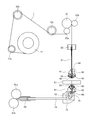
- FIG. 1 is a diagram illustrating a configuration of a wire electric discharge machine according to a first embodiment of the present invention.
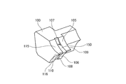
- FIG. 2 is a perspective view of an aspirator as a wire suction device according to the first embodiment.
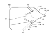
- FIG. 3 is a cross-sectional view of the aspirator when the aspirator according to the first embodiment is viewed from the direction of the rotation axis of the wire electrode recovery roller.
- FIG. 4 is a perspective view in a situation where the aspirator according to the first embodiment is used in close contact with the wire electrode recovery roller.
- FIG. 5 is another perspective view in a situation where the aspirator according to the first embodiment is used in close contact with the wire electrode recovery roller.
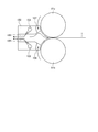
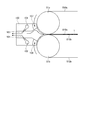
- FIG. 6 is a diagram illustrating a state in which the aspirator according to the first embodiment is viewed from the rotation axis direction in a state where the aspirator is used in close contact with the wire electrode recovery roller.
- FIG. 7 is a schematic diagram for explaining the operation of the wire recovery apparatus according to the first embodiment.
- FIG. 8 is a diagram illustrating a wire electrode collection delivery belt according to a second embodiment.
- FIG. 9 is a view showing a state in which the aspirator according to the second embodiment is viewed from the direction of the rotation axis in a situation where the aspirator is used in close contact with the wire electrode collection delivery belt.
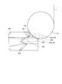
- FIG. 10 is a diagram illustrating a state in which the aspirator according to the third embodiment is viewed from the direction of the rotation axis in a situation where the aspirator is used in close contact with the lower roller.
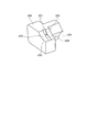
- FIG. 11 is a perspective view of an aspirator as a wire suction device according to the third embodiment.
- FIG. 1 is a diagram illustrating a configuration of a wire electric discharge machine according to a first embodiment of the present invention.
- the wire electric discharge machine includes a wire electrode bobbin 11 around which a wire electrode 1 is wound and a wire electrode holding portion including pulleys 12 a, 12 b, and 12 c that change the direction of the wire electrode 1.
- a wire electrode feed roller 21 that feeds the wire electrode 1 and the wire electrode 1 is provided with an upper wire electrode guide portion composed of a machining liquid nozzle 46.
- a wire guide recovery roller 81a, 81b for recovering the wire electrode 1 and a wire guide recovery roller 81a, 81b for recovering the wire electrode 1 is provided.
- a wire electrode recovery section comprising a wire electrode recovery pipe end 82 for separating the electrode 1 and fluid; Block 71, lower roller 72 that changes the direction of the wire electrode 1, and negative pressure that facilitates the conveyance of the wire electrode 1 from the lower die 63 to the lower guide 64, and at the same time, the wire electrode 1 is fed to the wire electrode recovery unit
- An aspirator 73 that ejects a fluid that facilitates conveyance, and a wire electrode feed section that includes a lower guide pipe 74 that guides the wire electrode 1 to the wire electrode collection section. The wire electrode 1 and the workpiece are collected while the wire electrode 1 is collected.
- a discharge is generated by applying a pulse voltage between the workpiece 51 and the workpiece 51, and the workpiece is processed into a sawtooth shape in an arbitrary shape while moving the workpiece 51, the upper wire electrode guide portion and the lower wire electrode guide portion relative to each other.
- a wire electrode 1 having a diameter of 0.3 mm to 0.1 mm, and further less than 0.1 mm is used.
- the wire electrode 1 is automatically sent to the wire electrode collection unit through the upper wire electrode guide unit, the processing start hole of the workpiece 51, the lower wire electrode guide unit, and the lower roller unit by the wire electrode automatic connection device. Is completed.
- FIG. 2 is a perspective view of an aspirator 100 as a wire suction device according to the present embodiment
- FIG. 3 is a cross-sectional view of the aspirator 100 viewed from the direction of the rotation axis of the wire electrode recovery rollers 81a and 81b.
- the aspirator 100 has curved surfaces 105 and 106 that can be brought into close contact with one side of the cylindrical peripheral surfaces of the wire electrode recovery rollers 81a and 81b on the first member 109 and similarly on the other side of the cylindrical peripheral surfaces. Closely curved surfaces 115 and 116 are provided on the second member 110, respectively.
- the curved surfaces 105 and 115 have the same shape as the peripheral surface of the wire electrode recovery roller 81a, and the curved surfaces 106 and 116 have the same shape as the peripheral surface of the wire electrode recovery roller 81b.
- the curved surfaces 105 and 106 form a first curved surface with a sharp portion sandwiched therebetween, and the curved surfaces 115 and 116 form a second curved surface with the sharp portion sandwiched therebetween.
- a suction groove 107 is formed between the curved surface 105 and the curved surface 115, and a suction groove 108 is formed between the curved surface 106 and the curved surface 116.
- the suction groove 108 has a certain width in the rotation axis direction of the wire electrode collection rollers 81a and 81b. Is formed. If the first member 109 and the second member 110 can be brought into close contact with the cylindrical peripheral surfaces of the wire electrode recovery rollers 81a and 81b, the width of the suction grooves 107 and 108 in the rotation axis direction is The width may not necessarily be constant.
- a through-hole 150 sandwiched between the first member 109 and the second member 110 is formed between the suction grooves 107 and 108, and the wire electrode 1 sucked in the through-hole 150 is connected to the wire electrode collection rollers 81a and 81b. It is possible to travel in the collecting direction from the discharge side.
- the first member 109, the second member 110, and the member (third member) that forms the suction grooves 107 and 108 by connecting them are integrally formed even if they are individual components. It doesn't matter.
- the aspirator 100 is used in close contact with the wire electrode collection rollers 81a and 81b in FIG. 4 and 5 are perspective views in this situation, and FIG. 6 is a view of the wire electrode recovery rollers 81a and 81b as viewed from the rotation axis direction.
- the aspirator 100 and the wire electrode recovery rollers 81a and 81b constitute a wire recovery device.
- Compressed air inlets 101 and 102 are formed in a member (third member) that forms the suction grooves 107 and 108 by connecting the first member 109 and the second member 110, and is provided from the outside. It is possible to introduce compressed air. Further, on the side surface of the third member on the side of the through hole 150, compressed air jets 103 and 104 facing the wire electrode recovery (discharge) direction are formed.
- the compressed air is introduced into the compressed air introduction ports 101 and 102 before the wire electrode 1 is transported to the wire recovery device, and the compressed air is ejected from the compressed air ejection ports 103 and 104, whereby the aspirator 100 serving as a suction mechanism is provided.
- a negative pressure is generated at the entrance of the through hole 150.
- outside air flows into the suction grooves 107 and 108 provided in the aspirator 100, so that the wire electrode 1 is separated from the wire electrode recovery rollers 81a and 81b.
- a fluid flow occurs along the line.
- the tip of the wire electrode 1 that is about to be wound around the wire electrode recovery rollers 81a and 81b is conveyed to the discharge side of the aspirator 100 without being wound around the wire electrode recovery rollers 81a and 81b due to the flow of the fluid.
- the compressed air inlet and the compressed air outlet are not necessarily formed in the third member, and may be formed in the first member 109 and the second member 110.
- Two or more compressed air jets which are fluid jets, may be formed as long as they face the wire electrode recovery direction.
- the compressed air is used to generate the negative pressure.
- the fluid is not limited to compressed air as long as the fluid can generate the negative pressure at the entrance of the through hole 150.
- the wrapping prevention of the wire electrode 1 is enhanced by concentrating the flow of outside air only on the flow along the suction grooves 107 and 108.
- FIG. 7 is a schematic diagram for explaining the operation of the wire recovery apparatus according to the present embodiment.
- the wire electrode 1 sandwiched from both sides by the wire electrode collection rollers 81a and 81b and conveyed to the wire collection device tries to be wound around the wire electrode collection rollers 81a and 81b
- the first member 109 and the second member 110 is peeled off from the wire electrode recovery rollers 81a and 81b by the flow of outside air flowing in along the suction grooves 107 and 108 formed between 110, thereby preventing winding.
- the wire electrode 1 is sucked into the negative pressure region of the through hole 150 of the aspirator 100 and is conveyed to the discharge side (collection direction) of the left aspirator 100 in FIG.
- both sides of each of the suction grooves 107 and 108 formed between the first member 109 and the second member 110 that can be in close contact with the wire electrode recovery rollers 81 a and 81 b are provided on the first member 109.
- the flow is blocked by the second member 110 and blocks the flow of outside air from the direction of the rotation axis of the wire electrode recovery rollers 81a and 81b.
- the rotation direction of the wire electrode recovery rollers 81a and 81b of the suction grooves 107 and 108 ( The width in the direction perpendicular to the paper surface in FIG. 7 is arbitrary, but it is sufficient if there is a width in the maximum range of movement of the wire electrode 1 carried out from the wire electrode recovery rollers 81a and 81b in the direction of the rotation axis.
- the suction force is strengthened by narrowing the width of the suction grooves 107 and 108 to the maximum range of movement of the wire electrode 1 in the rotation axis direction, and the peeling effect by the flow of outside air along the suction grooves 107 and 108 is further improved. Can be made.
- Embodiment 2 FIG.
- the mechanism for transporting the wire electrode 1 between the aspirator 100 is the wire electrode recovery rollers 81a and 81b has been described, but the mechanism for transporting the wire electrode 1 is limited to this. is not.
- the mechanism for transporting the wire electrode 1 with the wire recovery device of the wire electric discharge machine is not the wire electrode recovery rollers 81a and 81b shown in FIG. 1, but the wire electrode as shown in FIG. It is assumed that the recovery delivery belts 810a and 810b are used.
- the collection delivery belts 810a and 810b are stretched by wire electrode collection rollers 81a and 81c, 81b and 81d, respectively.
- wire electrode recovery rollers 81 a and 81 b that stretch the recovery delivery belts 810 a and 810 b on the discharge side of the wire electrode 1.
- the wire electrode 1 is drawn by being sandwiched from both sides (upper and lower) by the collection delivery belts 810a and 810b, and discharged toward the aspirator 100 installed as shown in FIG.
- the wire electrode 1 sandwiched between the collection delivery belts 810a and 810b and conveyed is in close contact with the region stretched by the wire electrode collection rollers 81a and 81b of the collection delivery belts 810a and 810b. It is sucked and collected by the aspirator 100.
- the aspirator 100 shown in FIG. 9 has the same configuration as that described in the first embodiment, and the wire electrode 1 is wound around a region stretched by the wire electrode collection rollers 81a and 81b of the collection delivery belts 810a and 810b.
- Embodiment 3 FIG.
- the method of providing the suction groove on the curved surface that can be closely opposed to the cylindrical shape is not limited to the wire recovery device, but the wire electric discharge machine shown in FIG.
- the present invention can also be applied to a wire suction device installed at a subsequent stage of the lower roller 72 that changes the direction of the wire electrode 1.
- An example of an aspirator 200 as such a wire suction device is shown in FIG.
- FIG. 11 is a perspective view of the aspirator 200.
- the aspirator 200 can be closely opposed to the cylindrical shape of the lower roller 72 as shown in FIG. 11 instead of a curved surface having a sharp portion that can be closely opposed to two cylindrical shapes like the aspirator 100.
- the curved surfaces 205 and 215 having various shapes are provided on the first member 209 and the second member 210, respectively.
- a suction groove 207 having a certain width in the rotation axis direction of the lower roller 72 is formed between the curved surfaces 205 and 215. If the first member 209 and the second member 210 can be in close contact with the cylindrical peripheral surface of the lower roller 72, the width of the suction groove 207 in the rotation axis direction is not necessarily constant. It doesn't matter.
- a through-hole 250 sandwiched between the first member 209 and the second member 210 is formed in contact with the suction groove 207, and the wire electrode 1 sucked in the through-hole 250 is sent out from the carry-out side of the lower roller 72 ( The vehicle can travel in the left direction in FIG.
- the first member 209, the second member 210, and the member (third member) forming the suction groove 207 by connecting the two members may be individual parts or integrally formed. I do not care.
- compressed air inlets 201 and 202 are formed in a member (third member) that connects the first member 209 and the second member 210 to form the suction groove 207. It is possible to introduce compressed air from the outside. Also, compressed air jets 203 and 204 are formed on the side surface of the third member on the side of the through-hole 250 so as to face the wire electrode delivery direction.
- the aspirator 200 is used in close contact with the lower roller 72 as shown in FIG.
- the through-hole 250 of the aspirator 200 that is a suction mechanism is provided.
- a negative pressure is generated at the entrance of the.
- outside air flows into the suction groove 207 provided in the aspirator 200, so that a fluid flows along the peripheral wall of the lower roller 72 so that the wire electrode 1 is peeled off from the lower roller 72.
- the tip of the wire electrode 1 that is about to be wound upward in FIG.
- the locations and number of compressed air inlets and compressed air outlets, and the type of fluid for generating negative pressure are not limited to the above.
- the suction force is improved.
- the width of the maximum range of movement of the wire electrode 1 carried out from the lower roller 72 in the direction of the rotation axis is sufficient. It is.
- the suction force can be strengthened, and the peeling effect due to the flow of outside air along the suction groove 207 can be further improved.
- the present invention is not limited to the above-described embodiment, and various modifications can be made without departing from the scope of the invention in the implementation stage.
- the above embodiments include inventions at various stages, and various inventions can be extracted by appropriately combining a plurality of disclosed constituent requirements. For example, even if some constituent requirements are deleted from all the constituent requirements shown in the embodiment, the problem described in the column of the problem to be solved by the invention can be solved, and is described in the column of the effect of the invention. When an effect is obtained, a configuration from which this configuration requirement is deleted can be extracted as an invention.
- the constituent elements over different embodiments may be appropriately combined.
- the wire suction device and the wire recovery device according to the present invention are useful for preventing the wire electrode used in the wire electric discharge machine from being wound around the roller, and particularly for the wire electrode having a diameter of less than 0.1 mm. It is suitable for a wire suction device and a wire recovery device that perform suction by an aspirator.
Landscapes
- Chemical & Material Sciences (AREA)
- Chemical Kinetics & Catalysis (AREA)
- Electrochemistry (AREA)
- Engineering & Computer Science (AREA)
- Mechanical Engineering (AREA)
- Electrical Discharge Machining, Electrochemical Machining, And Combined Machining (AREA)
- Cleaning In General (AREA)
Abstract
Priority Applications (5)
| Application Number | Priority Date | Filing Date | Title |
|---|---|---|---|
| PCT/JP2013/061108 WO2014167724A1 (fr) | 2013-04-12 | 2013-04-12 | Dispositif d'aspiration de fil et dispositif de collecte de fil |
| JP2013534523A JP5436728B1 (ja) | 2013-04-12 | 2013-04-12 | ワイヤ吸引装置およびワイヤ回収装置 |
| DE112013000109.8T DE112013000109B4 (de) | 2013-04-12 | 2013-04-12 | Drahtansaugvorrichtung und Drahteinziehvorrichtung |
| CN201380002222.0A CN104245202B (zh) | 2013-04-12 | 2013-04-12 | 线电极吸引装置及线电极回收装置 |
| US14/131,101 US9138820B2 (en) | 2013-04-12 | 2013-04-12 | Wire aspiration device and wire recovery device |
Applications Claiming Priority (1)
| Application Number | Priority Date | Filing Date | Title |
|---|---|---|---|
| PCT/JP2013/061108 WO2014167724A1 (fr) | 2013-04-12 | 2013-04-12 | Dispositif d'aspiration de fil et dispositif de collecte de fil |
Publications (1)
| Publication Number | Publication Date |
|---|---|
| WO2014167724A1 true WO2014167724A1 (fr) | 2014-10-16 |
Family
ID=50396666
Family Applications (1)
| Application Number | Title | Priority Date | Filing Date |
|---|---|---|---|
| PCT/JP2013/061108 Ceased WO2014167724A1 (fr) | 2013-04-12 | 2013-04-12 | Dispositif d'aspiration de fil et dispositif de collecte de fil |
Country Status (5)
| Country | Link |
|---|---|
| US (1) | US9138820B2 (fr) |
| JP (1) | JP5436728B1 (fr) |
| CN (1) | CN104245202B (fr) |
| DE (1) | DE112013000109B4 (fr) |
| WO (1) | WO2014167724A1 (fr) |
Cited By (4)
| Publication number | Priority date | Publication date | Assignee | Title |
|---|---|---|---|---|
| CN109834348A (zh) * | 2017-11-28 | 2019-06-04 | 株式会社沙迪克 | 线放电加工装置 |
| WO2020203132A1 (fr) * | 2019-03-29 | 2020-10-08 | 西部電機株式会社 | Dispositif de fourniture de fil-électrode et procédé de fourniture de fil-électrode |
| JP2020163559A (ja) * | 2020-02-25 | 2020-10-08 | 西部電機株式会社 | ワイヤ電極送出装置及びワイヤ電極送出方法 |
| JP2020163534A (ja) * | 2019-03-29 | 2020-10-08 | 西部電機株式会社 | ワイヤ電極送出装置及びワイヤ電極送出方法 |
Families Citing this family (7)
| Publication number | Priority date | Publication date | Assignee | Title |
|---|---|---|---|---|
| JP6219785B2 (ja) * | 2014-06-23 | 2017-10-25 | ファナック株式会社 | 断線修復手段を備えたワイヤ放電加工機 |
| US10272510B2 (en) * | 2016-01-14 | 2019-04-30 | United Technologies Corporation | Electrical discharge machining apparatus |
| JP6360212B1 (ja) * | 2017-01-31 | 2018-07-18 | ファナック株式会社 | ワイヤ放電加工機 |
| JP6753908B2 (ja) * | 2018-10-23 | 2020-09-09 | ファナック株式会社 | ワイヤ放電加工機のワイヤ回収装置 |
| CN113453832B (zh) * | 2019-02-25 | 2022-11-08 | 三菱电机株式会社 | 线放电加工装置的线自动接线装置 |
| CN115666837B (zh) * | 2020-05-29 | 2023-11-21 | 三菱电机株式会社 | 线电极回收装置及线放电加工装置 |
| CN121373605B (zh) * | 2025-12-25 | 2026-04-10 | 太原理工大学 | 一种薄材电解加工装置和薄材电解加工设备 |
Citations (6)
| Publication number | Priority date | Publication date | Assignee | Title |
|---|---|---|---|---|
| JPH0259221A (ja) * | 1988-08-24 | 1990-02-28 | Mitsubishi Electric Corp | ワイヤ放電加工装置 |
| JPH052830U (ja) * | 1991-01-16 | 1993-01-19 | 三菱電機株式会社 | ワイヤカツト放電加工機のワイヤ案内装置 |
| EP1602433A1 (fr) * | 2004-06-04 | 2005-12-07 | Charmilles Technologies S.A. | Guide en forme de V pour guider le fil usé dans une machine d'usinage par électroérosion par fil. |
| EP1611985A1 (fr) * | 2004-06-04 | 2006-01-04 | Charmilles Technologies S.A. | Pièce entonnoir utilisé pour guider le fil usé dans une machine d'usinage par électroérosion. |
| JP2006224215A (ja) * | 2005-02-16 | 2006-08-31 | Seibu Electric & Mach Co Ltd | ワイヤ放電加工機 |
| US20110239452A1 (en) * | 2010-03-30 | 2011-10-06 | Taiwan Wirecut Technologies Co., Ltd. | Auto-removing assembly for a wire electric discharge machine |
Family Cites Families (13)
| Publication number | Priority date | Publication date | Assignee | Title |
|---|---|---|---|---|
| JPH0796168B2 (ja) * | 1989-02-23 | 1995-10-18 | 三菱電機株式会社 | ワイヤ放電加工装置のワイヤ自動供給装置 |
| JPH0646833U (ja) | 1992-11-27 | 1994-06-28 | 株式会社牧野フライス製作所 | 牽引ローラのワイヤ電極巻き込み防止装置 |
| JP3097793B2 (ja) * | 1993-06-15 | 2000-10-10 | 矢崎総業株式会社 | 放電加工機用ワイヤの誘導装置を備えたワイヤ切断機 |
| JPH0994720A (ja) * | 1995-09-29 | 1997-04-08 | Sodick Co Ltd | ワイヤカット放電加工装置 |
| DE19607705C2 (de) * | 1996-02-29 | 2000-06-29 | Agie Sa | Drahtlaufsystem für eine Funkenerosionsvorrichtung |
| JP3347599B2 (ja) * | 1996-09-12 | 2002-11-20 | 矢崎総業株式会社 | 長尺体の切断方法および切断装置 |
| JPH10277844A (ja) * | 1997-03-31 | 1998-10-20 | K H S:Kk | ワイヤカット放電加工装置のワイヤ電極処理方法と装置及びワイヤカット放電加工装置 |
| JP2000296416A (ja) | 1999-04-13 | 2000-10-24 | Seibu Electric & Mach Co Ltd | ワイヤ放電加工機におけるワイヤ送り装置 |
| DE10009556C2 (de) * | 2000-02-29 | 2002-08-01 | Agie Sa | Drahtspannsystem für eine Funkenerosionsvorrichtung |
| JP3815436B2 (ja) * | 2000-09-28 | 2006-08-30 | 三菱電機株式会社 | ワイヤ放電加工装置 |
| DE502004007290D1 (de) * | 2004-09-08 | 2008-07-10 | Agie Sa | Drahtschneideeinrichtung, Drahtlaufsystem sowie Verfahren zum Zerteilen einer Drahtelektrode in einer Funkenerosionsvorrichtung |
| TWM319103U (en) * | 2007-01-29 | 2007-09-21 | Max See Industry Co Ltd | Wire-concentrating mechanism of wire-cutting machine |
| CH697785B1 (fr) * | 2008-03-13 | 2009-02-13 | Agie Sa | Dispositif destiné à tronçonner le fil usé sur une machine d'électroérosion. |
-
2013
- 2013-04-12 WO PCT/JP2013/061108 patent/WO2014167724A1/fr not_active Ceased
- 2013-04-12 DE DE112013000109.8T patent/DE112013000109B4/de active Active
- 2013-04-12 US US14/131,101 patent/US9138820B2/en not_active Expired - Fee Related
- 2013-04-12 JP JP2013534523A patent/JP5436728B1/ja active Active
- 2013-04-12 CN CN201380002222.0A patent/CN104245202B/zh active Active
Patent Citations (6)
| Publication number | Priority date | Publication date | Assignee | Title |
|---|---|---|---|---|
| JPH0259221A (ja) * | 1988-08-24 | 1990-02-28 | Mitsubishi Electric Corp | ワイヤ放電加工装置 |
| JPH052830U (ja) * | 1991-01-16 | 1993-01-19 | 三菱電機株式会社 | ワイヤカツト放電加工機のワイヤ案内装置 |
| EP1602433A1 (fr) * | 2004-06-04 | 2005-12-07 | Charmilles Technologies S.A. | Guide en forme de V pour guider le fil usé dans une machine d'usinage par électroérosion par fil. |
| EP1611985A1 (fr) * | 2004-06-04 | 2006-01-04 | Charmilles Technologies S.A. | Pièce entonnoir utilisé pour guider le fil usé dans une machine d'usinage par électroérosion. |
| JP2006224215A (ja) * | 2005-02-16 | 2006-08-31 | Seibu Electric & Mach Co Ltd | ワイヤ放電加工機 |
| US20110239452A1 (en) * | 2010-03-30 | 2011-10-06 | Taiwan Wirecut Technologies Co., Ltd. | Auto-removing assembly for a wire electric discharge machine |
Cited By (9)
| Publication number | Priority date | Publication date | Assignee | Title |
|---|---|---|---|---|
| CN109834348A (zh) * | 2017-11-28 | 2019-06-04 | 株式会社沙迪克 | 线放电加工装置 |
| KR20190062192A (ko) * | 2017-11-28 | 2019-06-05 | 가부시키가이샤 소딕 | 와이어 방전 가공 장치 |
| KR102183253B1 (ko) | 2017-11-28 | 2020-11-25 | 가부시키가이샤 소딕 | 와이어 방전 가공 장치 |
| WO2020203132A1 (fr) * | 2019-03-29 | 2020-10-08 | 西部電機株式会社 | Dispositif de fourniture de fil-électrode et procédé de fourniture de fil-électrode |
| JP2020163534A (ja) * | 2019-03-29 | 2020-10-08 | 西部電機株式会社 | ワイヤ電極送出装置及びワイヤ電極送出方法 |
| CN112689547A (zh) * | 2019-03-29 | 2021-04-20 | 西部电机株式会社 | 线电极送出装置及线电极送出方法 |
| US11819936B2 (en) | 2019-03-29 | 2023-11-21 | Seibu Electric & Machinery Co., Ltd. | Wire electrode feeding apparatus and wire electrode feeding method |
| JP2020163559A (ja) * | 2020-02-25 | 2020-10-08 | 西部電機株式会社 | ワイヤ電極送出装置及びワイヤ電極送出方法 |
| JP7254736B2 (ja) | 2020-02-25 | 2023-04-10 | 西部電機株式会社 | ワイヤ電極送出装置及びワイヤ電極送出方法 |
Also Published As
| Publication number | Publication date |
|---|---|
| US20140305908A1 (en) | 2014-10-16 |
| DE112013000109T5 (de) | 2014-12-18 |
| CN104245202B (zh) | 2016-06-22 |
| DE112013000109B4 (de) | 2022-12-01 |
| JP5436728B1 (ja) | 2014-03-05 |
| US9138820B2 (en) | 2015-09-22 |
| JPWO2014167724A1 (ja) | 2017-02-16 |
| CN104245202A (zh) | 2014-12-24 |
Similar Documents
| Publication | Publication Date | Title |
|---|---|---|
| JP5436728B1 (ja) | ワイヤ吸引装置およびワイヤ回収装置 | |
| CN106029275B (zh) | 线放电加工装置 | |
| US9217225B2 (en) | Paper manufacturing | |
| WO2001028725A1 (fr) | Systeme d'alimentation automatique de fil d'une machine de decoupe de fil par decharge electrique | |
| JP5225516B1 (ja) | ワイヤ電極送り装置およびワイヤ放電加工機 | |
| JP5062384B1 (ja) | ワイヤ放電加工機、及びそのワイヤ電極送り方法 | |
| JP6605564B2 (ja) | ワイヤ放電加工装置 | |
| JPH0592322A (ja) | ワイヤ放電加工機の圧力流体によるワイヤ電極の搬送装置 | |
| JP4331119B2 (ja) | ワイヤ放電加工機 | |
| JPS62188627A (ja) | ワイヤ放電加工装置 | |
| CN115666837B (zh) | 线电极回收装置及线放电加工装置 | |
| JP2005158293A (ja) | 固体高分子膜型燃料電池セルの製造方法 | |
| JP2813593B2 (ja) | ワイヤの下部引出し装置 | |
| CN106029274B (zh) | 线放电加工装置 | |
| CN112689547B (zh) | 线电极送出装置及线电极送出方法 | |
| JP4808639B2 (ja) | 鋼帯連続処理設備の溶接時先行鋼帯ループ作成方法 | |
| JPS63283825A (ja) | ワイヤカット放電加工機のワイヤ排出装置 | |
| CN117983911A (zh) | 线放电加工装置 | |
| JP2008012644A (ja) | ワイヤカット放電加工装置 | |
| JPWO2001028725A1 (ja) | ワイヤ放電加工装置のワイヤ自動供給装置 | |
| JP2016185588A (ja) | ラベル切断装置 |
Legal Events
| Date | Code | Title | Description |
|---|---|---|---|
| ENP | Entry into the national phase |
Ref document number: 2013534523 Country of ref document: JP Kind code of ref document: A |
|
| WWE | Wipo information: entry into national phase |
Ref document number: 14131101 Country of ref document: US |
|
| WWE | Wipo information: entry into national phase |
Ref document number: 112013000109 Country of ref document: DE Ref document number: 1120130001098 Country of ref document: DE |
|
| 121 | Ep: the epo has been informed by wipo that ep was designated in this application |
Ref document number: 13881777 Country of ref document: EP Kind code of ref document: A1 |
|
| 122 | Ep: pct application non-entry in european phase |
Ref document number: 13881777 Country of ref document: EP Kind code of ref document: A1 |