WO2014168038A1 - Structure de piston d'embrayage - Google Patents
Structure de piston d'embrayage Download PDFInfo
- Publication number
- WO2014168038A1 WO2014168038A1 PCT/JP2014/059498 JP2014059498W WO2014168038A1 WO 2014168038 A1 WO2014168038 A1 WO 2014168038A1 JP 2014059498 W JP2014059498 W JP 2014059498W WO 2014168038 A1 WO2014168038 A1 WO 2014168038A1
- Authority
- WO
- WIPO (PCT)
- Prior art keywords
- clutch
- piston
- partition wall
- chamber
- arm
- Prior art date
- Legal status (The legal status is an assumption and is not a legal conclusion. Google has not performed a legal analysis and makes no representation as to the accuracy of the status listed.)
- Ceased
Links
Images


Classifications
-
- F—MECHANICAL ENGINEERING; LIGHTING; HEATING; WEAPONS; BLASTING
- F16—ENGINEERING ELEMENTS AND UNITS; GENERAL MEASURES FOR PRODUCING AND MAINTAINING EFFECTIVE FUNCTIONING OF MACHINES OR INSTALLATIONS; THERMAL INSULATION IN GENERAL
- F16D—COUPLINGS FOR TRANSMITTING ROTATION; CLUTCHES; BRAKES
- F16D25/00—Fluid-actuated clutches
- F16D25/06—Fluid-actuated clutches in which the fluid actuates a piston incorporated in, i.e. rotating with the clutch
- F16D25/062—Fluid-actuated clutches in which the fluid actuates a piston incorporated in, i.e. rotating with the clutch the clutch having friction surfaces
- F16D25/063—Fluid-actuated clutches in which the fluid actuates a piston incorporated in, i.e. rotating with the clutch the clutch having friction surfaces with clutch members exclusively moving axially
- F16D25/0635—Fluid-actuated clutches in which the fluid actuates a piston incorporated in, i.e. rotating with the clutch the clutch having friction surfaces with clutch members exclusively moving axially with flat friction surfaces, e.g. discs
- F16D25/0638—Fluid-actuated clutches in which the fluid actuates a piston incorporated in, i.e. rotating with the clutch the clutch having friction surfaces with clutch members exclusively moving axially with flat friction surfaces, e.g. discs with more than two discs, e.g. multiple lamellae
-
- F—MECHANICAL ENGINEERING; LIGHTING; HEATING; WEAPONS; BLASTING
- F16—ENGINEERING ELEMENTS AND UNITS; GENERAL MEASURES FOR PRODUCING AND MAINTAINING EFFECTIVE FUNCTIONING OF MACHINES OR INSTALLATIONS; THERMAL INSULATION IN GENERAL
- F16D—COUPLINGS FOR TRANSMITTING ROTATION; CLUTCHES; BRAKES
- F16D25/00—Fluid-actuated clutches
- F16D25/08—Fluid-actuated clutches with fluid-actuated member not rotating with a clutching member
- F16D25/082—Fluid-actuated clutches with fluid-actuated member not rotating with a clutching member the line of action of the fluid-actuated members co-inciding with the axis of rotation
- F16D25/083—Actuators therefor
-
- F—MECHANICAL ENGINEERING; LIGHTING; HEATING; WEAPONS; BLASTING
- F16—ENGINEERING ELEMENTS AND UNITS; GENERAL MEASURES FOR PRODUCING AND MAINTAINING EFFECTIVE FUNCTIONING OF MACHINES OR INSTALLATIONS; THERMAL INSULATION IN GENERAL
- F16D—COUPLINGS FOR TRANSMITTING ROTATION; CLUTCHES; BRAKES
- F16D2300/00—Special features for couplings or clutches
- F16D2300/08—Details or arrangements of sealings not provided for in group F16D3/84
Definitions
- the present invention relates to a clutch piston structure, and more particularly, to a clutch piston structure having an elastic seal member that seals a dry clutch and a space in which oil such as lubricating oil exists and follows the drive of the clutch piston.
- a clutch piston structure that includes an elastic seal member that seals the dry multi-plate clutch and a space where oil on the piston side exists and expands and contracts following the driving of the piston (for example, Patent Document 1).
- This conventional clutch piston structure is applied to a drive transmission device in which a dry multi-plate clutch for connecting and disconnecting transmission of driving force is arranged on the inner periphery of a motor.
- the clutch piston includes an arm that passes through the partition wall of the clutch drum that rotates integrally with the rotating shaft and fastens the dry multi-plate clutch. Further, an elastic seal material is interposed between the clutch piston and the dry multi-plate clutch.
- This elastic seal member divides the space on the dry multi-plate clutch side of the partition wall into an elastic seal chamber into which oil on the clutch piston side enters and a clutch chamber in which the dry multi-plate clutch is disposed, and the clutch piston It has elasticity so that it can be displaced in the axial direction as it is driven. Therefore, even if the oil of the bearing of the rotating shaft enters the elastic seal chamber through the hole through which the arm penetrates in the partition wall, it does not reach the dry multi-plate clutch due to the seal of the elastic seal member.
- the elastic seal member is required not only to seal the elastic seal chamber and the clutch chamber but also to have a strength sufficient to prevent breakage due to the hydraulic pressure due to the centrifugal force.
- the present invention has been made paying attention to the above problem, and an object of the present invention is to provide a clutch piston structure capable of reducing the stress acting on the elastic seal member when the rotary shaft rotates.
- an elastic seal member for sealing a space between an arm-side elastic seal chamber and a dry clutch-side clutch chamber is provided on a partition wall provided so as to be rotatable integrally with a rotary shaft.
- a clutch piston structure is provided in which the partition wall is provided with a partition wall communication hole that connects the elastic seal chamber and the piston housing chamber at a position on the outer diameter side of the arm through hole.
- the oil positioned outside the arm through hole is a piston having a drain pressure. Due to the pressure difference with the storage chamber, it moves to the piston storage chamber through the partition wall communication hole. For this reason, it is possible to suppress the hydraulic pressure due to the centrifugal force in the elastic seal chamber when the rotary shaft rotates, as compared with a case where no partition wall communication hole is provided. Thereby, in this invention, compared with what does not provide a partition communicating hole, it becomes possible to prevent the failure
- FIG. 1 is an overall schematic diagram illustrating a hybrid driving force transmission device including a clutch piston structure according to a first embodiment. It is principal part sectional drawing which shows the structure of the multi-plate dry clutch of the motor & clutch unit in the said hybrid driving force transmission apparatus.
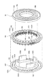
- FIG. 3 is an exploded side view showing a piston assembly of a multi-plate dry clutch in the hybrid driving force transmission device.
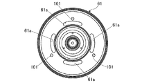
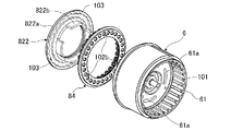
- FIG. 3 is an exploded perspective view showing a piston assembly of a multi-plate dry clutch in the hybrid driving force transmission device. It is the front view which looked at the partition of the clutch piston structure of Embodiment 1 from the axial direction.
- FIG. 1 is an overall schematic diagram showing a hybrid driving force transmission device including the clutch piston structure of the first embodiment. The overall configuration of the apparatus will be described below with reference to FIG.
- the hybrid driving force transmission device includes an engine Eng, a motor & clutch unit M / C, a transmission unit T / M, an engine output shaft 1, a clutch hub shaft 2, and a clutch hub. 3, a clutch drum shaft (rotary shaft) 4, a transmission input shaft 5, a clutch drum 6, a dry multi-plate clutch (dry clutch) 7, a slave cylinder 8, and a motor / generator 9. Yes.
- the slave cylinder 8 that hydraulically controls engagement / release of the dry multi-plate clutch 7 is generally called “CSC” (concentric slave cylinder).
- the hybrid driving force transmission device connects the motor / generator 9 and the transmission input shaft 5 via the clutch drum 6 and the clutch drum shaft 4 when the dry multi-plate clutch 7 that is normally open is opened. "Running mode”.
- the dry multi-plate clutch 7 is hydraulically engaged by the slave cylinder 8, the “hybrid vehicle running mode” in which the engine Eng and the motor / generator 9 are connected is set. That is, the dry multi-plate clutch 7 includes a clutch hub 3 coupled to the clutch hub shaft 2 coupled to the engine output shaft 1 via the damper 21 and a clutch drum 6 input from the motor / generator 9 when engaged. Are connected.
- the motor & clutch unit M / C has a dry multi-plate clutch 7, a slave cylinder 8, and a motor / generator 9.
- the dry multi-plate clutch 7 is connected to the engine Eng to connect and disconnect the driving force transmitted from the engine Eng.
- the slave cylinder 8 hydraulically controls engagement / release of the dry multi-plate clutch 7.
- the motor / generator 9 is disposed at the outer peripheral position of the clutch drum 6 of the dry multi-plate clutch 7 and transmits power to the transmission input shaft 5.
- the motor & clutch unit M / C is provided with a cylinder housing 81 having a first clutch pressure oil passage 85 to the slave cylinder 8 while maintaining a sealing property by the O-ring 10.
- the motor / generator 9 is a synchronous AC motor, and includes a rotor support frame 91 provided integrally with the clutch drum 6 and a rotor 92 supported and fixed to the rotor support frame 91 and embedded with permanent magnets. And it has the stator 94 arrange
- the cylinder housing 81 is formed with a water jacket 96 for circulating cooling water.
- the transmission unit T / M is connected to the motor & clutch unit M / C and includes a transmission housing 41, a V-belt type continuously variable transmission mechanism 42, and an oil pump O / P.
- the V-belt type continuously variable transmission mechanism 42 is built in the transmission housing 41, spans a V-belt between two pulleys, and changes the belt contact diameter to obtain a continuously variable transmission ratio.
- the oil pump O / P is a hydraulic pressure source that produces the hydraulic pressure to the necessary part.
- the oil pump pressure is used as the original pressure, and the oil pressure from the control valve (not shown) that regulates the shift hydraulic pressure, clutch / brake hydraulic pressure, etc. to the pulley chamber. Guide the hydraulic pressure to the required part.
- the transmission unit T / M is further provided with a forward / reverse switching mechanism 43, an oil tank 44, and an end plate 45.
- the end plate 45 has a second clutch pressure oil passage 47 (see FIG. 2).
- the oil pump O / P drives the pump by transmitting the rotational drive torque of the transmission input shaft 5 via the chain drive mechanism.
- the chain drive mechanism includes a drive-side sprocket 51 that rotates as the transmission input shaft 5 rotates, a driven-side sprocket 52 that rotates the pump shaft 57, and a chain 53 that spans both the sprockets 51 and 52.
- the drive-side sprocket 51 is interposed between the transmission input shaft 5 and the end plate 45, and is rotatably supported via a bush 55 with respect to a stator shaft 54 fixed to the transmission housing 41. Then, the rotational input torque from the transmission input shaft 5 is transmitted through the first adapter 56 that is spline-fitted to the transmission input shaft 5 and claw-fitted to the drive-side sprocket 51.
- FIG. 2 is a cross-sectional view of the main part showing the configuration of the motor and clutch unit in the hybrid driving force transmission device.
- FIG. 3 is an exploded side view showing the piston assembly of the dry multi-plate clutch in the hybrid driving force transmission device, and
- FIG. 4 is an exploded perspective view showing the piston assembly.
- the configuration of the motor & clutch unit M / C will be described below with reference to FIGS.
- the clutch hub 3 is connected to the engine output shaft 1 of the engine Eng.
- the clutch hub 3 holds a drive plate 71 of the dry multi-plate clutch 7 by spline coupling.
- the clutch drum 6 is connected to the transmission input shaft 5 of the transmission unit T / M via the clutch drum shaft 4.
- the clutch drum 6 holds the driven plate 72 of the dry multi-plate clutch 7 by spline coupling.
- the dry-type multi-plate clutch 7 is formed by alternately arranging a plurality of drive plates 71 and driven plates 72 having friction facings 73 and 73 attached on both surfaces between the clutch hub 3 and the clutch drum 6. Be dressed.
- the drive plate 71 rotates together coaxially with the clutch hub shaft 2.
- the driven plate 72 rotates coaxially with the clutch drum shaft 4. That is, when the dry multi-plate clutch 7 is fastened, torque can be transmitted between the clutch hub 3 and the clutch drum 6, and by opening the dry multi-plate clutch 7, between the clutch hub 3 and the clutch drum 6. Shut off torque transmission.
- the slave cylinder 8 is a hydraulic actuator that controls the engagement / release of the dry multi-plate clutch 7, and is disposed at a position between the transmission unit T / M side and the clutch drum 6.
- the slave cylinder 8 includes a clutch piston 82, a first clutch pressure oil passage 85, and a cylinder oil chamber 86.
- the clutch piston 82 is slidable with respect to the cylinder hole 80 of the cylinder housing 81.
- the first clutch pressure oil passage 85 is formed in the cylinder housing 81 and guides the clutch pressure created by the transmission unit T / M.
- the cylinder oil chamber 86 communicates with the first clutch pressure oil passage 85 and applies hydraulic pressure to the clutch piston 82.
- the clutch piston 82 includes a pressure receiving member 821, an arm member 822, and a needle bearing 823. As shown in FIG. 2, the clutch piston 82 can be frictionally engaged with the drive plate 71 by pressing the driven plate 72 in the axial direction by the arm protrusion 822 b of the arm member 822. Further, the clutch piston 72 rotates together coaxially with the clutch drum shaft 4.
- the pressure receiving member 821 receives the hydraulic pressure of the cylinder oil chamber 86, and slides in the axial direction along the cylinder hole 80 in the right direction in the drawing.
- the arm member 822 presses the dry multi-plate clutch 7 in the fastening direction by the pressing force by the hydraulic pressure received by the pressure receiving member 821.
- the arm member 822 includes a disk-shaped arm body 822a, an arm protrusion (arm) 822b penetrating an arm through hole 61a (see FIG. 2) formed in the partition wall 61 of the clutch drum 6, It has.
- the partition wall 61 is coupled to the outer periphery of the clutch drum shaft 4 so as to be able to rotate integrally with the clutch drum shaft 4, and is disposed between the dry multi-plate clutch 7 and the clutch piston 82, and is a clutch chamber on the dry multi-plate clutch 7 side.
- 89b is separated from the piston housing chamber 89c on the clutch piston 82 side.
- the partition wall 61 is formed with an arm through hole 61a through which an arm protrusion 822b extending from the clutch piston 82 to the driven plate 72 passes.
- the needle bearing 823 is interposed between the pressure receiving member 821 and the arm member 822, and suppresses the pressure receiving member 821 from rotating with the rotation of the arm member 822.
- a spring retainer 84 is interposed between the arm body 822 a of the arm member 822 of the clutch piston 82 and the partition wall 61 of the clutch drum 6.
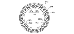
- the spring retainer 84 includes a retainer member 84a formed in a thin ring shape and a plurality of return springs 84b held by the retainer member 84a.
- one end of the return spring 84b is seated in a support groove 822c (see FIG. 5C) on the surface 822d side which is the surface of the arm member 822 of the clutch piston 82 on the dry multi-plate clutch 7 side.
- the other end of the return spring 84b is fitted on the outer periphery of a cylindrical flange 84f provided upright around a through hole opened in the retainer member 84a and is seated on the retainer member 84a.
- an elastic seal member 88 is fixed to the partition 61 on the dry multi-plate clutch 7 side.
- This elastic seal member 88 covers the arm through hole 61a in the space on the dry multi-plate clutch 7 side of the partition wall 61, and the space on the dry multi-plate clutch 7 side of the partition wall 61 from the arm through hole 61a and the arm protrusion 822b.
- a side elastic seal chamber 89a and a clutch chamber 89b on the dry type multi-plate clutch 7 side are divided to seal between the two chambers 89a and 89b.
- the clutch chamber 89b is separated from the motor chamber 65 by the seal member 62, and is separated from the damper 21 (see FIG. 1) side by the seal member 15.
- This elastic seal member 88 can be elastically deformed following the stroke operation of the arm protrusion 822b, and rotates together with the clutch drum shaft 4 coaxially. That is, the elastic seal member 88 includes an arm press-fit plate 88a and a bellows elastic support member 88b.
- the arm press-fitting plate 88a is formed in a hat cross-sectional shape with metal or the like, the arm ridge 822b is press-fitted, and is interposed between the arm ridge 822b and the dry multi-plate clutch 7.
- the arm press-fit plate 88a is provided integrally with sheet-like bellows elastic support members 88b, 88b having elasticity such as rubber, and the inner peripheral portion and the outer peripheral portion of the bellows elastic support members 88b, 88b are the partition walls 61 of the clutch drum 6. It is press-fitted and fixed to.
- the elastic seal member 88 divides the elastic seal chamber 89a and the clutch chamber 89b and seals between them, and the lubricating oil or leak oil as the oil on the clutch piston 82 side is dry-type multi-plate clutch. Block the flow to 7. That is, the elastic seal member 88 defines a wet space (elastic seal chamber 89a) in which the slave cylinder 8 is disposed and a dry space (clutch chamber 89b) in which the dry multi-plate clutch 7 is disposed.
- a piston housing chamber 89c is formed in which the arm member 822 moves when the clutch piston 82 moves in the axial direction.
- the piston housing chamber 89c is connected to the drain side, and serves as a bearing lubricating oil path for returning the bearing lubricating oil described below and leaking oil from the sliding portion of the clutch piston 82 to the drain side of the atmospheric pressure. .
- the bearing lubricating oil passage includes the needle bearing 20, the second seal member 14, the first axial oil passage 19, the second axial oil passage 18, the lubricating oil passage 16, and the gap shown in FIG. 17, a first seal member 31, a first recovery oil passage 33, and a second recovery oil passage 34.
- the first recovery oil passage 33 and the second recovery oil passage 34 connected to the drain side are disposed at the outer diameter side position in the piston accommodation chamber 89c. For this reason, in the piston accommodating chamber 89c, when the clutch drum shaft 4 rotates, the bearing lubricating oil flows from the clutch drum shaft 4 side in the outer diameter direction.
- the second seal member 14 seals the bearing lubricant from flowing from the wet space in which the slave cylinder 8 is disposed into the dry space in which the dry multi-plate clutch 7 is disposed.
- the bearing lubricant from the transmission unit T / M passes through the needle bearing 20 and the first bearing 12 that rotatably supports the clutch drum 6 with respect to the cylinder housing 81 as indicated by the arrow Oa. It is guided to the piston accommodating chamber 89c. Further, the bearing lubricating oil passes through the needle bearing 823 in the piston housing chamber 89c, and then passes through the first recovery oil passage 33 and the second recovery oil passage 34, and the atmospheric pressure of the transmission unit T / M. Return to the drain side. Further, a part of the lubricating oil guided to the piston accommodating chamber 89c through the bearing lubricating oil passage passes through the arm through hole 61a and flows into the elastic seal chamber 89a as indicated by an arrow Ob.
- the partition wall communication hole 101, the retainer communication portion 102, and the piston communication portion 103 are provided as a path for returning the lubricating oil flowing into the elastic seal chamber 89a to the drain side when the clutch drum shaft 4 rotates. ing.
- the partition wall communication hole 101 is provided so as to penetrate the partition wall 61 in the axial direction, is located on the outer diameter side of the arm through hole 61a, and communicates with the elastic seal chamber 89a and the piston housing chamber 89c. It arrange
- the retainer communication portion 102 includes a through hole 102a formed through the retainer member 84a and a notch portion 102b formed by cutting out from the inner periphery of the retainer member 84a into a substantially triangular shape in the outer diameter direction.
- the through hole 102a is formed through the retainer member 84a in order to raise the cylindrical flange 84f for seating in the retainer member 84a in a state of being fitted to the inner periphery of each return spring 84b. It is a hole.
- this through-hole 102a is arrange
- the cutout portion 102b is formed by cutting a substantially triangular shape from the inner peripheral edge 84c of the retainer member 84a in the outer diameter direction. It is arranged at the place. And the notch part 102b is arrange
- one of the three partition wall communication holes 101 in the circumferential direction overlaps both the through hole 102a and the notch portion 102b when projected in the axial direction, and the other two partition wall communication holes 101, 101 are When projected in the axial direction, it overlaps the tip of the notch 102b. Accordingly, the partition wall communication holes 101 provided at the three locations are respectively communicated with the piston housing chamber 89c in the axial direction via the retainer communication portion 102.
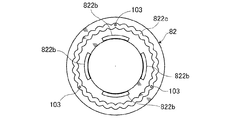
- the piston communication part 103 is formed so as to penetrate the arm member 822 of the clutch piston 82 in the axial direction at the position of the bottom of the support groove 822c. Further, the piston communication portion 103 is arranged at three positions so that the phase in the circumferential direction coincides with the partition wall communication hole 101 when the arm protrusion 822b is inserted into the arm through hole 61a.
- the operation in the clutch piston assembly process will be described (assembly process).
- the arm member 822 and the spring retainer 84 of the clutch piston 82 shown in FIG. 6A are set in an assembled state in which the spring retainer 84 is assembled to the arm member 822 as shown in FIG. 6B.
- the assembled arm member 822 and spring retainer 84 are assembled to the partition wall 61 of the clutch drum 6 as shown in FIG. 6C.
- any one of the three notches 102b of the retainer member 84a is positioned at the position of the piston communication portion 103 of the arm member 822 of the clutch piston 82. Assemble and match.
- the arm member 822 assembled with the spring retainer 84 is assembled to the partition wall 61 of the clutch drum 6, the three notches 102b of the retainer member 84a, the three partition communication holes 101 of the partition wall 61, Assemble them so that their circumferential positions match.
- the three partition wall communication holes 101 in the circumferential direction of the partition wall 61 are disposed across the through hole 102a and the notch portion 102b at one position when viewed in the axial direction. In two places, it is arranged so as to overlap the tip of the notch 102b.
- the bearing lubricant from the transmission unit T / M is guided to the piston accommodating chamber 89c through the path indicated by the arrow Oa. Further, a part of the bearing lubricating oil in the piston accommodating chamber 89c passes through the arm through hole 61a and flows into the elastic seal chamber 89a as indicated by an arrow Ob.
- the elastic seal member 88 has not only simply sealed the elastic seal chamber 89a and the clutch chamber 89b, but also has a strength sufficient to prevent damage due to hydraulic pressure due to the centrifugal force.
- the lubricating oil in the elastic seal chamber 89a has a pressure difference from the piston accommodating chamber 89c connected to the drain side when the centrifugal force acts and the hydraulic pressure rises. For this reason, as shown by the arrow Oc in FIG. 2, it moves to the piston accommodation chamber 89c through the partition wall communication hole 101 and the retainer communication part 102.
- the partition wall communication hole 101 is disposed at the outermost radial position of the elastic seal chamber 89a, almost all of the lubricating oil subjected to centrifugal force enters the piston housing chamber 89c. Moving.
- the partition wall communication hole 101 is inclined such that the end on the outer diameter side thereof is disposed at the position on the outer side in the piston accommodating chamber 89c rather than the end on the elastic seal chamber 89a side. This movement of the lubricating oil becomes more reliable.
- the lubricating oil closer to the partition wall 61 than the arm member 822 passes through the piston communication portion 103 formed so as to penetrate the arm member 822, and the first recovered oil on the drain side (low pressure side). Guided to the passage 33 and the second recovery oil passage 34 (see arrow Oc in FIG. 2).
- the clutch piston structure of Embodiment 1 is A dry multi-plate clutch 7 as a dry clutch composed of a driven plate 72 that rotates coaxially with the clutch drum shaft 4 as a rotating shaft, and a drive plate 71 that can be frictionally fastened to the driven plate 72; A clutch piston 82 that presses the driven plate 72 in an axial direction to be frictionally engaged with the drive plate 71, and rotates coaxially with the clutch drum shaft 4; A piston housing chamber 89c in which the clutch piston 82 is disposed and oil flows in an outer diameter direction from the clutch drum shaft 4 side;
- the dry multi-plate clutch is provided between the dry multi-plate clutch 7 and the clutch piston 82 and has an arm through hole 61a through which an arm protrusion 822b extending from the clutch piston 82 to the driven plate 72 passes.
- a partition wall 61 that divides the clutch chamber 89b on the 7 side and the piston accommodating chamber 89c, and rotates coaxially with the clutch drum shaft 4; By covering the arm through hole 89c, it is divided into the clutch chamber 89b and an elastic seal chamber 89a on the partition wall 61 side, and can be elastically deformed following the stroke operation of the arm protrusion 822b, and the clutch drum An elastic seal member 88 that rotates coaxially with the shaft 4; With The partition wall 61 further includes a partition wall communication hole 101 which is provided at a position radially outside the arm through hole 61a so as to penetrate in the axial direction and communicate the elastic seal chamber 89a and the piston housing chamber 89c. , It is characterized by that.
- the first embodiment is characterized in that the partition wall communication hole 101 is disposed at the outermost radial position of the elastic seal chamber 89a.
- the clutch piston structure of Embodiment 1 is A return spring 84b that pushes back the clutch piston 82 in a direction opposite to the pressing direction is interposed between the partition wall 61 and the clutch piston 82, and an annular plate retainer member that seats the return spring 84b on the partition wall 61.
- 84a is in contact with the partition wall 61,
- the retainer member 84a is provided with a retainer communication portion 102 that allows the partition wall communication hole 101 and the piston accommodating chamber 89c to communicate with each other in the axial direction.
- the lubricating oil in the elastic seal chamber 89a when the lubricating oil in the elastic seal chamber 89a is moved from the partition wall communication hole 101 to the piston housing chamber 89c by centrifugal force, it is reliably moved in the axial direction from the partition wall communication hole 101 via the retainer communication portion 102. be able to. Therefore, the lubricating oil in the elastic seal chamber 89a can be moved to the piston accommodating chamber 89c more reliably, and the required strength of the elastic seal member 88 can be further reduced as compared with the case where the retainer communication portion 102 is not provided. It becomes.
- the retainer communicating portion 102 uses the through hole 102a and the notch portion 102b that penetrate the retainer member 84a, the retainer member 84a is provided between the outer periphery of the retainer member 84a and the inner periphery of the outer cylinder portion of the clutch drum 6. It is not necessary to secure a flow path for the lubricating oil. As a result, the radial distance between the retainer member 84a and the outer cylinder portion of the clutch drum 6 can be reduced to reduce the outer diameter of the clutch drum 6, and the motor / generator 9 and the clutch unit M / C can be made compact. It becomes.
- the radial positions of the partition wall communication hole 101 and the through hole 102a and the notch part 102b as the retainer communication part 102 are matched. For this reason, if the partition wall communication hole 101 is disposed so as to coincide with either the through hole 102a or the notch portion 102b in the circumferential direction, the piston accommodating chamber is provided via one or both of the through hole 102a and the notch portion 102b. 89c is communicated. Therefore, the positioning operation for arranging the partition wall communication hole 101 and the retainer communication portion 102 so as to overlap in the axial direction is facilitated.
- the clutch piston structure of the first embodiment is A piston communication portion 103 is provided which penetrates the arm member 822 of the clutch piston 82 in the axial direction and communicates the partition wall 61 side and the drain side of the piston housing chamber 89c. Therefore, it becomes unnecessary to secure a lubricating oil passage between the outer periphery of the clutch piston 82 and the inner periphery of the outer cylinder portion of the clutch drum 6. As a result, the radial distance between the clutch piston 82 and the outer cylinder portion of the clutch drum 6 can be narrowed to reduce the outer diameter of the clutch drum 6, and the motor / generator 9 and the clutch unit M / C can be made compact. It becomes.
- the clutch piston structure of the first embodiment is The partition wall communication hole 101, the retainer communication portion 102, and the piston communication portion 103 are arranged so that the positions in the circumferential direction coincide with each other at least one place when the clutch piston 82, the retainer member 84a, and the partition wall 61 are disposed at the set positions.
- the phase in the circumferential direction is set. Therefore, when the arm member 822, the retainer member 84a, and the partition wall 61 are arranged at the set positions and assembled, the partition wall communication hole 101, the retainer communication portion 102, and the piston communication portion 103 are arranged in series in the axial direction. Can be made.
- circumferential positioning is performed using the notch 102b of the retainer communication portion 102 and the piston communication portion 103 as marks. Can do. Therefore, the assembling work efficiency can be improved as compared with the case where the notch portion 102b and the piston communication portion 103 are arranged in different phases in the circumferential direction.
- circumferential positioning is performed using the notch portion 102b of the retainer communication portion 102 and the partition wall communication hole 101 as marks. it can.
- the assembly work efficiency can be improved as compared with the case where the phase in the circumferential direction of the partition wall communication hole 101 and the notch 102b does not match.
- the assembly operation can be fully automated by reading the partition communication hole 101, the retainer communication portion 102, and the piston communication portion 103 with the sensor as a mark.
- the clutch piston structure of Embodiment 1 is A motor / generator 9 is provided on the outer periphery of the partition wall 61.
- the clutch drum shaft 4 as a rotating shaft is characterized in that at least one of rotational energy can be exchanged with a motor / generator 9 as a rotating electrical machine. That is, in the first embodiment, the clutch drum shaft 4 can be rotated by receiving rotational energy when the motor / generator 9 is powered, while the rotational energy can be converted into electric power when the motor / generator 9 is regenerated. did.
- the clutch drum 6 can be made compact as described in the above (2) and (3). As a result, the motor / generator 9 and the clutch unit M / C can be made more compact.
- Embodiment 2 Next, the clutch piston structure of Embodiment 2 is demonstrated based on FIG. Since the second embodiment is a modification of the first embodiment, only differences from the first embodiment will be described, and the description of the configuration common to the first embodiment will be omitted.
- the notch portion 102b is provided as a retainer communication portion for communicating the partition wall communication hole 101 and the piston accommodating chamber 89c. That is, all the notches 102b are arranged at different positions in the radial direction with respect to the through holes 102a that are penetrated to form the flanges 84f for supporting the return springs 84b. And the vertex of the triangle which forms the notch part 102b is arrange
- the partition wall communication hole 101 shown above the central axis in FIG. 7 is counterclockwise in the second embodiment by 1/2 of the circumferential pitch of the through holes 102a. The position is shifted in the direction.
- the piston communication portion 103 (not shown in FIG. 8) corresponding to this position is arranged with a position shifted in the circumferential direction together with the partition wall communication hole 101.
- the circumferential direction of the arm member 822 of the clutch piston 82 is achieved by allowing all the piston communication portions 103 to overlap each notch portion 102b.
- the position can be positioned.
- the circumferential position with respect to the partition wall 61 can be positioned by making all the partition wall communication holes 101 overlap each notch portion 102b.
- the clutch piston structure of Embodiment 2 is
- the retainer communication portion 102 is a notch portion 102 b that is notched radially from the inner periphery of the retainer member 84. Therefore, as compared with the case where the retainer communication portion 102 is formed in a hole shape, when the same flow rate is secured, it is not necessary to provide the inner peripheral edge 84c of the retainer member 84a closer to the inner diameter side than the retainer communication portion 102.
- the retainer member 84a can be formed with a small diameter.
- Embodiment 1 when the inner peripheral edge 84c of the retainer member 84a is prescribed
- the power transmission device of the present invention can also be applied to an engine driving force transmission device in which only an engine is mounted as a drive source and a dry clutch is used as a starting clutch, like an engine vehicle.
- the present invention can also be applied to a motor driving force transmission device in which only a motor / generator is mounted as a driving source and a dry clutch is a starting clutch, such as an electric vehicle or a fuel cell vehicle.
- the scope of application of the present invention is not limited to vehicles, but can be applied to other than vehicles such as industrial equipment. Therefore, although the clutch drum shaft 4 rotated by the motor / generator is shown as the rotating shaft, any rotating shaft can be applied as long as it rotates integrally with the partition wall.
- the dry multi-clutch clutch is used as the dry clutch.
- a single-plate dry clutch or the like can be used.
- an example of a dry clutch by normal opening has been shown.
- the present invention can also be applied to a normally closed dry clutch using a diaphragm spring or the like.
- the drive plate of the dry multi-plate clutch has friction facing
- the driven plate may have a friction facing.
- the partition wall through hole is disposed at the outermost radial position of the elastic seal chamber, but the present invention is not limited to this. At least, if the partition through hole is arranged in the outer diameter direction than the arm through hole, the hydraulic pressure generated by the centrifugal force of the oil in the elastic seal chamber is reduced compared to the structure without the partition through hole, The required strength of the elastic seal member can be reduced.
- the oil may be oil for pressure transmission in addition to lubricating oil.
- the retainer communication portion the example using the through hole and the notch portion and the two examples of only the notch portion are shown, but the present invention is not limited to this, and only the through hole is the retainer communication portion.
- the partition wall communication hole is arranged at a position in the inner diameter direction from the inner peripheral edge of the retainer member, the inner portion of the retainer member can be used as the retainer communication portion.
- the retainer member is formed by penetrating the retainer communicating portion has been described.
- the means for guiding oil from the partition wall communicating hole to the piston housing chamber is not limited to the means that penetrates the retainer member. .
- a recess may be provided.
- the oil guided to the outer peripheral edge of the retainer member can move to the drain side through between the outer periphery of the retainer member and the inner periphery of the cylindrical portion of the clutch drum.
- the piston storage chamber is connected to the drain side.
- the oil from the elastic seal chamber can be returned to the drain side.
- the example in which the partition wall communication hole, the retainer communication portion, and the piston communication portion are provided at three locations in the circumferential direction has been shown, but these may be provided at least at one location in the circumferential direction.
- the number is not limited to 3 shown in the embodiment.
- the numbers of the partition wall communication holes, the retainer communication portions, and the piston communication portions can be varied. For example, when the number of partition wall communication holes is 3, as shown in the embodiment, the piston communication part is 6 or 9, and the position of one partition wall communication hole and the position of one piston communication part are matched. If so, the piston communication portions may be arranged in the axial direction of all the partition wall communication holes.
- the number of retainer communication portions can be reduced (for example, 1) relative to the number of partition wall communication holes.
- the piston communication portions are also the same, and the number thereof may be larger or smaller than the number of partition wall communication holes. Further, when the numbers of the partition wall communication holes, the retainer communication portions, and the piston communication portions are inconsistent in this manner, the partition wall communication holes, the retainer communication portions, and the grooves that communicate the piston communication portions in the circumferential direction are provided in the circumferential direction. It may be provided.
Landscapes
- Engineering & Computer Science (AREA)
- General Engineering & Computer Science (AREA)
- Mechanical Engineering (AREA)
- Hydraulic Clutches, Magnetic Clutches, Fluid Clutches, And Fluid Joints (AREA)
Abstract
L'invention porte sur une structure de piston d'embrayage capable de réduire une contrainte agissant sur un élément de joint élastique pendant la rotation d'un arbre rotatif. La structure de piston d'embrayage est caractérisée en ce qu'elle comprend : une cloison (61) placée entre un embrayage multidisque à bain d'huile (7) et un piston d'embrayage (82) et comprenant un trou traversant de bras (61a); et un joint de joint élastique (88) placé sur le côté embrayage multidisque à bain d'huile (7) de la cloison (61), qui établit une étanchéité entre une chambre d'embrayage (89b) sur le côté embrayage multidisque à bain d'huile (7) et une chambre de joint élastique (89a) sur le côté trou traversant de bras (61a) et le côté saillie de bras (822b) et qui peut se déformer élastiquement conjointement avec l'action de course de la saillie de bras (822b); et un trou de communication de cloison (101) qui traverse la cloison (61) et qui relie la chambre de joint élastique (89a) et une chambre de logement de piston (89c) dans une position qui est plus sur le côté diamètre extérieur que le trou traversant de bras (61a).
Priority Applications (1)
| Application Number | Priority Date | Filing Date | Title |
|---|---|---|---|
| JP2015511215A JP6056962B2 (ja) | 2013-04-11 | 2014-03-31 | クラッチピストン構造 |
Applications Claiming Priority (2)
| Application Number | Priority Date | Filing Date | Title |
|---|---|---|---|
| JP2013-082861 | 2013-04-11 | ||
| JP2013082861 | 2013-04-11 |
Publications (1)
| Publication Number | Publication Date |
|---|---|
| WO2014168038A1 true WO2014168038A1 (fr) | 2014-10-16 |
Family
ID=51689448
Family Applications (1)
| Application Number | Title | Priority Date | Filing Date |
|---|---|---|---|
| PCT/JP2014/059498 Ceased WO2014168038A1 (fr) | 2013-04-11 | 2014-03-31 | Structure de piston d'embrayage |
Country Status (2)
| Country | Link |
|---|---|
| JP (1) | JP6056962B2 (fr) |
| WO (1) | WO2014168038A1 (fr) |
Cited By (3)
| Publication number | Priority date | Publication date | Assignee | Title |
|---|---|---|---|---|
| CN106996428A (zh) * | 2016-01-25 | 2017-08-01 | 法雷奥离合器公司 | 尤其用于机动车辆的离合器止挡件 |
| NL2018447A (nl) * | 2016-03-17 | 2017-09-26 | Gkn Stromag Ag | Fluïdum aangedreven schakelbare koppeling of -rem |
| WO2020157255A1 (fr) * | 2019-01-31 | 2020-08-06 | Valeo Embrayages | Double embrayage humide et dispositif de rappel elastique pour un tel double embrayage humide |
Citations (3)
| Publication number | Priority date | Publication date | Assignee | Title |
|---|---|---|---|---|
| JP2009185874A (ja) * | 2008-02-05 | 2009-08-20 | Sinfonia Technology Co Ltd | 電磁連結装置 |
| JP2010286112A (ja) * | 2009-05-12 | 2010-12-24 | Nissan Motor Co Ltd | 駆動力伝達装置 |
| JP2012052562A (ja) * | 2010-08-31 | 2012-03-15 | Nissan Motor Co Ltd | 駆動力伝達装置 |
-
2014
- 2014-03-31 WO PCT/JP2014/059498 patent/WO2014168038A1/fr not_active Ceased
- 2014-03-31 JP JP2015511215A patent/JP6056962B2/ja active Active
Patent Citations (3)
| Publication number | Priority date | Publication date | Assignee | Title |
|---|---|---|---|---|
| JP2009185874A (ja) * | 2008-02-05 | 2009-08-20 | Sinfonia Technology Co Ltd | 電磁連結装置 |
| JP2010286112A (ja) * | 2009-05-12 | 2010-12-24 | Nissan Motor Co Ltd | 駆動力伝達装置 |
| JP2012052562A (ja) * | 2010-08-31 | 2012-03-15 | Nissan Motor Co Ltd | 駆動力伝達装置 |
Cited By (5)
| Publication number | Priority date | Publication date | Assignee | Title |
|---|---|---|---|---|
| CN106996428A (zh) * | 2016-01-25 | 2017-08-01 | 法雷奥离合器公司 | 尤其用于机动车辆的离合器止挡件 |
| CN106996428B (zh) * | 2016-01-25 | 2020-10-30 | 法雷奥离合器公司 | 尤其用于机动车辆的离合器止挡件 |
| NL2018447A (nl) * | 2016-03-17 | 2017-09-26 | Gkn Stromag Ag | Fluïdum aangedreven schakelbare koppeling of -rem |
| WO2020157255A1 (fr) * | 2019-01-31 | 2020-08-06 | Valeo Embrayages | Double embrayage humide et dispositif de rappel elastique pour un tel double embrayage humide |
| FR3092373A1 (fr) * | 2019-01-31 | 2020-08-07 | Valeo Embrayages | Double embrayage humide et dispositif de rappel elastique pour un tel double embrayage humide |
Also Published As
| Publication number | Publication date |
|---|---|
| JPWO2014168038A1 (ja) | 2017-02-16 |
| JP6056962B2 (ja) | 2017-01-11 |
Similar Documents
| Publication | Publication Date | Title |
|---|---|---|
| JP5471823B2 (ja) | 駆動力伝達装置 | |
| CN102906439B (zh) | 驱动力传递装置 | |
| JP5499998B2 (ja) | 駆動力伝達装置 | |
| US9222524B2 (en) | Drive force transmission device | |
| JP5853761B2 (ja) | 駆動力伝達装置 | |
| JP5776781B2 (ja) | 駆動力伝達装置 | |
| JP5772974B2 (ja) | 電動車両の駆動力伝達装置 | |
| WO2013084970A1 (fr) | Dispositif de transmission de force motrice | |
| JP6056962B2 (ja) | クラッチピストン構造 | |
| JP5565093B2 (ja) | 駆動力伝達装置 | |
| JP2013002522A (ja) | 駆動力伝達装置 | |
| CN113383176A (zh) | 摩擦接合装置 | |
| JP2013113431A (ja) | 駆動力伝達装置 | |
| KR102616855B1 (ko) | 하이브리드 구동 모듈 | |
| JP2014109345A (ja) | 駆動力伝達装置 |
Legal Events
| Date | Code | Title | Description |
|---|---|---|---|
| 121 | Ep: the epo has been informed by wipo that ep was designated in this application |
Ref document number: 14783233 Country of ref document: EP Kind code of ref document: A1 |
|
| DPE1 | Request for preliminary examination filed after expiration of 19th month from priority date (pct application filed from 20040101) | ||
| ENP | Entry into the national phase |
Ref document number: 2015511215 Country of ref document: JP Kind code of ref document: A |
|
| NENP | Non-entry into the national phase |
Ref country code: DE |
|
| 122 | Ep: pct application non-entry in european phase |
Ref document number: 14783233 Country of ref document: EP Kind code of ref document: A1 |