WO2014171421A1 - Appareil de séparation solide-liquide et procédé de séparation solide-liquide - Google Patents
Appareil de séparation solide-liquide et procédé de séparation solide-liquide Download PDFInfo
- Publication number
- WO2014171421A1 WO2014171421A1 PCT/JP2014/060608 JP2014060608W WO2014171421A1 WO 2014171421 A1 WO2014171421 A1 WO 2014171421A1 JP 2014060608 W JP2014060608 W JP 2014060608W WO 2014171421 A1 WO2014171421 A1 WO 2014171421A1
- Authority
- WO
- WIPO (PCT)
- Prior art keywords
- zone
- solid
- water tank
- treated
- inner cylinder
- Prior art date
- Legal status (The legal status is an assumption and is not a legal conclusion. Google has not performed a legal analysis and makes no representation as to the accuracy of the status listed.)
- Ceased
Links
Images







Classifications
-
- B—PERFORMING OPERATIONS; TRANSPORTING
- B01—PHYSICAL OR CHEMICAL PROCESSES OR APPARATUS IN GENERAL
- B01D—SEPARATION
- B01D21/00—Separation of suspended solid particles from liquids by sedimentation
- B01D21/02—Settling tanks with single outlets for the separated liquid
- B01D21/08—Settling tanks with single outlets for the separated liquid provided with flocculating compartments
-
- B—PERFORMING OPERATIONS; TRANSPORTING
- B01—PHYSICAL OR CHEMICAL PROCESSES OR APPARATUS IN GENERAL
- B01D—SEPARATION
- B01D21/00—Separation of suspended solid particles from liquids by sedimentation
- B01D21/24—Feed or discharge mechanisms for settling tanks
- B01D21/2405—Feed mechanisms for settling tanks
Definitions
- the present invention relates to a solid-liquid separation device and a solid-liquid separation method.
- This solid-liquid separator has a double water tank structure in which a bottomed cylindrical inner cylinder water tank is accommodated inside a bottomed cylindrical outer cylinder water tank and the bottom of the outer cylinder water tank and the bottom of the inner cylinder water tank are separated from each other.
- flocs that overflow from the inner cylinder water tank are formed by introducing the raw water supplied with the flocculant into the lower part of the inner cylinder water tank to form a flock growth zone in the inner cylinder water tank.
- JP 2010-274199 A (FIG. 3)
- the present invention has been made to solve such problems, and an object of the present invention is to provide a solid-liquid separation apparatus and a solid-liquid separation method capable of further clarifying treated water.
- a solid-liquid separation device supplements a water to be treated introduction unit for introducing water to be treated, and solids in the water to be treated introduced from the water introduction unit to be treated.
- a solid-liquid separation device having a floc growth zone for growing a floc grown in the flock growth zone and a floc that has descended from the downflow zone. It has a separation zone that separates from the water to be treated after passing through the floc growth zone, and an upflow zone that raises the water to be treated in which the floc is separated in the separation zone.
- flocs grown in the floc growth zone are smoothly lowered from the floc growth zone in the downward flow zone and are smoothly conveyed to the separation zone to be separated from the water to be treated. Is done.
- the treated water from which the floc has been separated in the separation zone rises smoothly in the upflow zone.
- the upflow zone and the downflow zone are formed at different positions when viewed from above and below, and the lower end region of the upflow zone and the lower end region of the downflow zone are separated via the separation zone. You may communicate.
- the water to be treated descends the downflow zone, flows from the lower end side region of the downflow zone to the separation zone, passes through the separation zone and flows from the lower end side region to the upflow zone, A flow ascending the upflow zone is formed. Since the upflow zone and the downflow zone are formed at different positions when viewed from above and below, it is possible to prevent flocs from being blocked by the upflow or rising on the upflow. .
- the solid-liquid separator may have a double bottom structure including a first bottom and a second bottom, and the separation zone may be between the first bottom and the second bottom. With such a configuration, a sufficient space between the first bottom and the second bottom can be used as the separation zone.
- the downflow zone and the upflow zone may be separated. With such a configuration, it is possible to more surely prevent the floc from being prevented from sinking by the upward flow or from rising on the upward flow.
- the downflow zone and the upflow zone may be separated.
- the downflow zone and the upflow zone can be separated with a simple configuration in which only a partition is provided.
- the downflow zone and the upflow zone may be separated from each other.
- the distance between the downflow zone and the upflow zone it is possible to sufficiently secure the crossflow settling distance in the separation zone.
- a bottomed cylindrical inner cylinder water tank having a second bottom is accommodated inside a bottomed cylindrical outer cylinder water tank having a first bottom, and an outer cylinder water tank and an inner cylinder water tank And a plurality of partition plates that divide the annular intermediate region into a plurality of regions along the circumferential direction.
- the zone and the upflow zone may be separated.
- the downflow zone rides in a downward flow and sinks smoothly, and is smoothly transported and deposited on the second bottom of the outer cylinder water tank, and the water to be treated accompanying the flock is stored in the outer cylinder water tank. It is separated from the flocs at the second bottom of the upper part, and is smoothly lifted and carried upward in the upward flow zone partitioned by the downward flow zone and the partition plate.
- the upward flow zone that is lifted and carried upward is separated by a partition plate to form a flow in one direction. Therefore, it is possible to prevent the sedimentation of the floc from being hindered by the upward flow or the floc rising on the upward flow. Therefore, the SS concentration of the treated water can be lowered and the treated water can be further clarified.
- the upper end of the inner cylinder tank corresponding to the downflow zone partitioned by the partition plate may be set lower than the upper end of the inner cylinder tank in the area adjacent to the downflow zone.
- the lower end of the inner cylinder tank and the lower end of the partition plate corresponding to the downward flow zone partitioned by the partition plate may be extended downward from the lower end of the inner cylinder tank of the upward flow zone.
- the lower end of the inner cylinder water tank and the lower end of the partition plate corresponding to the downward flow zone extend downward from the lower end of the inner cylinder water tank of the upward flow zone. It is suppressed that the water to be treated rising in the flow zone is wound up, and the treated water can be further clarified.
- a solid-liquid separation method is a solid-liquid separation method in which water to be treated is allowed to pass through a floc growth zone, and the floc grown in the floc growth zone is lowered in one direction.
- the same operations and effects as the above-described solid-liquid separation device can be achieved.
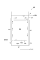
- FIG. 1 is a schematic cross-sectional configuration diagram showing a solid-liquid separation device (aggregation precipitation device) according to a first embodiment of the present invention.
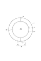
- FIG. 2 is a plan view of the solid-liquid separation device (coagulation sedimentation device) shown in FIG.
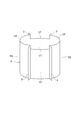
- FIG. 3 is a perspective view showing the inner cylinder water tank and the partition plate in FIGS. 1 and 2.
- FIG. 4 is a plan view showing a solid-liquid separation device (coagulation sedimentation device) according to a second embodiment of the present invention.
- FIG. 5 is a perspective view showing the inner cylinder water tank and the partition plate in FIG. 4.
- FIG. 6 is a perspective view showing an inner cylinder water tank and a partition plate of a solid-liquid separator (coagulation sedimentation apparatus) according to a third embodiment of the present invention.
- FIG. 7 is a perspective view showing an inner cylinder water tank and a partition plate of a solid-liquid separator (coagulation sedimentation apparatus) according to a fourth embodiment of the present invention.
- FIG. 8 is a schematic configuration diagram showing a solid-liquid separation device according to the fifth embodiment of the present invention.
- FIG. 9 is a schematic cross-sectional view along the line IX-IX shown in FIG.
- FIG. 10 is a schematic cross-sectional view along the line XX shown in FIG.
- FIG. 11 is a schematic configuration diagram showing a solid-liquid separation device according to the sixth embodiment of the present invention.
- FIG. 12 is a schematic cross-sectional view along the line XII-XII shown in FIG.
- FIG. 13 is a schematic block diagram which shows the solid-liquid separator which concerns on 7th Embodiment of this invention.
- 14 is a schematic cross-sectional view along the line XIV-XIV shown in FIG.
- the solid-liquid separation device includes a treated water introduction unit that introduces treated water, and a floc growth that supplements solids in the treated water introduced from the treated water introduction unit and that grows flocs using the treated water. If it has a zone, a structure will not be specifically limited.
- FIG. 1 is a schematic configuration diagram showing a coagulation sedimentation apparatus according to a first embodiment of the present invention
- FIG. 2 is a plan view of the coagulation sedimentation apparatus shown in FIG. 1
- FIG. 3 is an inner cylinder in FIGS. It is a perspective view which shows a water tank and a partition plate.
- a coagulation sedimentation apparatus (solid-liquid separation apparatus) 100 includes a bottomed cylindrical outer cylinder water tank 1 and a smaller diameter and a smaller height than the outer cylinder water tank 1. 1 and a bottomed cylindrical inner cylinder water tank 2 accommodated coaxially in the interior of 1.
- the bottom part (second bottom part) of the inner cylinder water tank 2 is spaced apart from the bottom part (first bottom part) of the outer cylinder water tank 1 by a predetermined length, and a double water tank structure is formed.
- the outer cylinder water tank 1 and the inner cylinder water tank 2 are made into the cylindrical shape here, a square tube shape may be sufficient.
- An introduction pipe (treated water introduction part) 4 for introducing raw water (treated water) into the tank is inserted through the tank peripheral wall at the lower part of the outer cylindrical water tank 1 and the tank peripheral wall at the lower part of the inner cylindrical water tank 2 And it has entered the inner cylinder water tank 2.
- the raw water is, for example, an organic waste water mixed with an inorganic flocculant such as PAC (polyaluminum chloride).
- a flocculant supply line L ⁇ b> 1 for supplying a polymer flocculant such as an anionic polymer is connected to the introduction pipe 4.
- an annular (cylindrical) intermediate region R formed between the outer cylinder water tank 1 and the inner cylinder water tank 2 is surrounded by A plurality of partition plates 3 that are divided into a plurality of regions along the direction are provided.
- the number of the partition plates 3 is two here, and the intermediate region R is divided into two by the partition plate 3 into one region R1 (downflow zone) and another region (adjacent region, upflow zone) R2.
- the outer edge part is connected with the inner peripheral surface of the outer cylinder water tank 1, and the inner edge part is connected with the outer peripheral surface of the inner cylinder water tank 2.
- the inner cylinder water tank 2 is connected to the outer cylinder water tank 1.
- the partition plate 3 is provided from the upper end to the lower end of the inner cylinder water tank 2, and the inner cylinder water tank upper end U1 corresponding to one region R1 partitioned by the partition plate 3 is more than the inner cylinder water tank upper end U2 of the adjacent region R2. It is set low, and here it is lowered by about 1 to 100 cm.
- the raw water containing the coagulant is uniformly ejected from the introduction pipe 4 in the inner cylinder water tank 2 to the lower part in the inner cylinder water tank 2, and
- the flocs are formed by mixing with stirring force, shearing force and the like.
- the flocs formed in the inner cylindrical water tank 2 are accumulated from the bottom, and further, the fluidized bed in the floc zone is formed by the supplied raw water.
- the raw water containing the flocculant ascends in the floc zone, the generated small flocs are captured by the previously generated flocs, thereby further growing the flocs in the inner cylinder tank 2.
- the raw water is clarified as if it had been filtered in the floc growth zone RX.
- the clarified water that has passed through the flock growth zone RX rises in the outer cylinder tank 1.
- a dispersion pipe (also referred to as a distributor) described in Japanese Patent Application Laid-Open No. 2010-274199 is disposed at the bottom of the inner cylindrical water tank 2, and raw water flows out from the dispersion pipe while rotating the dispersion pipe. By doing so, the raw water may be evenly distributed in the inner cylinder water tank 2 and uniformly raised to form the flock growth zone RX.
- the floc grown in the floc growth zone RX overflows unilaterally from the lower inner cylinder tank upper end U1 to the corresponding one region R1, and flows downward using the one region R1 as the floc sedimentation zone. It settles smoothly on the water and is smoothly transported to the bottom of the outer cylinder water tank 1 and deposited.
- the water carried along with the flock and carried to the bottom of the outer cylinder water tank 1 is separated from the flock at the bottom of the outer cylinder water tank 1, and the water flows upward with the region R2 adjacent to the one region R1 as the separated water rising zone. Rides smoothly and rises and is carried upwards.
- the concentrated floc accumulated at the bottom in the outer tubular water tank 1 is discharged to the outside from the concentrated floc discharge section 8 provided at the center of the bottom of the outer tubular water tank 1 and the clarified water rising in the outer tubular water tank 1 (Supernatant water) is discharged to the subsequent stage as treated water from the treated water discharge port 9 provided in the upper part of the outer tubular water tank 1.
- the intermediate region R is separated from the flock by the region R1 in which the partition plate 3 causes the flock to sink to the bottom of the outer tubular water tank 1 by the downward flow. Is separated from the bottom portion in the outer tubular tank 1 by the upward flow and conveyed to the adjacent region R2 along the circumferential direction, so that a flow in one direction is formed. In other words, the floc does not rise on an upward flow, so that the SS concentration of the treated water can be lowered and the treated water can be further clarified.
- the coagulation sedimentation apparatus (solid-liquid separation apparatus) 100 supplements the introduction pipe (treatment water introduction part) 4 for introducing the treatment water and the solid matter in the treatment water introduced from the introduction pipe 4. And a floc growth zone RX for growing flocs with the water to be treated.
- the coagulation sedimentation apparatus 100 floc grows one region R1 as a downward flow zone for lowering the floc grown in the floc growth zone RX in one direction from the floc growth zone RX and the floc descending from the downward flow zone. It has a separation zone that separates from the treated water after passing through the zone RX, and an adjacent region R2 as an adjacent upward flow zone that raises the treated water from which flocs have been separated in the separation zone.
- the separation zone is formed in a region between the bottom of the inner cylindrical water tank 2 and the bottom of the outer cylindrical water tank 1.
- flocs grown in the floc growth zone RX smoothly descend the downflow zone from the floc growth zone RX and are smoothly transported to the separation zone to be separated from the water to be treated. Is done.
- the treated water from which the floc has been separated in the separation zone rises smoothly in the upflow zone.
- the sedimentation of the floc is hindered by the upward flow or the floc rises on the upward flow. Can be suppressed. Therefore, the SS concentration of the treated water can be lowered and the treated water can be further clarified.
- the upflow zone and the downflow zone are formed at different positions when viewed from above and below (the state shown in FIG. 2), and are located at the lower end side of the upflow zone and the lower end side of the downflow zone.
- the areas communicate through a separation zone.
- a downflow zone is formed in a part of the circumferential direction of the coagulation sedimentation apparatus 100 (the right half area on the paper surface) and the other area (the left half area on the paper surface).
- An upflow zone is formed.
- the water to be treated descends the downflow zone, flows from the lower end side region of the downflow zone to the separation zone, passes through the separation zone and flows from the lower end side region to the upflow zone, A flow ascending the upflow zone is formed. Since the upflow zone and the downflow zone are formed at different positions when viewed from above and below, it is possible to prevent flocs from being blocked by the upflow or rising on the upflow. .
- the coagulation sedimentation apparatus 100 has a double bottom structure composed of a first bottom and a second bottom, and a separation zone is located between the first bottom and the second bottom. With such a configuration, a sufficient space between the first bottom and the second bottom can be used as the separation zone.
- the downward flow zone and the upward flow zone are separated. With such a configuration, it is possible to more surely prevent the floc from being prevented from sinking by the upward flow or from rising on the upward flow.
- the downward flow zone and the upward flow zone are separated.
- the downflow zone and the upflow zone can be separated with a simple configuration in which only a partition is provided.
- the solid-liquid separation method is a solid-liquid separation method that separates solid-liquid by passing water to be treated through the flock growth zone RX.
- the solid-liquid separation method includes a lowering step for lowering the floc grown in the floc growth zone RX in one direction, a separation step for separating the floc lowered in the lowering step and the water to be treated after passing through the floc growth zone, And an ascending step of raising the water to be treated from which the floc has been separated in the step.
- FIG. 4 is a plan view showing a coagulation sedimentation apparatus according to the second embodiment of the present invention
- FIG. 5 is a perspective view showing an inner cylinder water tank and a partition plate in FIG.
- the difference between the coagulation sedimentation apparatus of the second embodiment and the coagulation sedimentation apparatus of the first embodiment is that four partition plates 3 are used and the intermediate region R is divided into four by these partition plates 3.
- region R1 is 1st Embodiment. It is the same. Therefore, by the partition plate 3 divided into four, the lower inner cylinder water tank upper end U1 and the adjacent upper inner cylinder water tank upper end U2 are alternately arranged in parallel between the partition plates 3 and 3 along the circumferential direction. .
- FIG. 6 is a perspective view showing the inner cylinder water tank and partition plate of the coagulation sedimentation apparatus according to the third embodiment of the present invention
- FIG. 7 is the inner cylinder water tank and partition of the coagulation sedimentation apparatus according to the fourth embodiment of the present invention. It is a perspective view which shows a board.
- the difference between the coagulation sedimentation apparatus of the third embodiment and the coagulation sedimentation apparatus of the first embodiment, and the difference of the coagulation sedimentation apparatus of the fourth embodiment from the coagulation sedimentation apparatus of the second embodiment are the upper end U1 of the inner cylinder water tank.
- the lower end D1 of the inner cylinder water tank and the lower end D3 of the partition plate 3 corresponding to the one area R1 set to be low extend from the lower end D2 of the inner cylinder water tank of the adjacent area R2.
- the lower end D1 of the inner cylinder water tank and the lower end D3 of the partition plate 3 corresponding to one region R1 are extended by about 1 to 100 cm.
- region R1 and the lower end D3 of the partition plate 3 are extended below from the inner cylinder water tank lower end D2 of adjacent area
- FIG. 8 is a schematic configuration diagram showing a solid-liquid separation device according to a fifth embodiment of the present invention.
- FIG. 9 is a schematic cross-sectional view along the line IX-IX shown in FIG.
- FIG. 10 is a schematic cross-sectional view along the line XX shown in FIG.
- the solid-liquid separator 200 includes an outer cylinder water tank 201 and an inner cylinder water tank 202.
- the inner side of the inner cylinder water tank 202 is configured as a flock growth zone that supplements the solid matter in the for-treatment water introduced from the for-treatment water introduction part 14 and grows the floc using the for-treatment water.
- the solid-liquid separation device 200 includes a water to be treated introduction unit 14 that introduces water to be treated into the inner cylindrical water tank 202.
- a treated water discharge port 19 for discharging the clarified water (supernatant water) that has risen in the outer cylinder water tank 201 is provided in the upper part of the outer cylinder water tank 201.
- the outer cylinder water tank 201 has a configuration in which a portion (intermediate region R) corresponding to the outer peripheral surface of the inner cylinder water tank 202 is divided into a plurality of circulation portions 203 in the outer cylinder water tank as shown in FIG. .
- the circulation part 203 is provided on the outer peripheral surface of the inner cylinder water tank 202 so as to extend in the vertical direction.
- the circulation parts 203 are provided at positions spaced apart from each other so as to be substantially equidistant in the circumferential direction of the inner cylindrical water tank 202.
- four distribution units 203 are provided, but the quantity is not particularly limited.
- One of the circulation parts 203 facing each other is configured as a downward flow zone RD and the other is configured as an upward flow zone RU.
- the upflow zone RU and the downflow zone RD are formed at different positions when viewed from the up-down direction.
- the downflow zone RD and the upflow zone RU are separated.
- separation means that the section in which the downflow zone RD is formed and the section in which the upflow zone RU are formed are independent of each other, and the flow of the water to be treated interferes with each other. It shows that it is in a state that is not in trouble.
- each circulation part 203 is spaced apart in the circumferential direction, the downward flow zone RD and the upward flow zone RU are separated by being separated from each other.
- the state in which the downward flow zone RD and the upward flow zone RU are separated from each other means that the downward flow zone RD is formed in one section and is spaced apart from the one section. In this state, the upflow zone RU is formed in another section provided at the position.
- the state in which the downward flow zone RD and the upward flow zone RU are separated from each other is an aspect of the state in which the downward flow zone RD and the upward flow zone RU are separated.
- the solid-liquid separation device 200 has a double bottom structure including a bottom portion (first bottom portion) 201a of the outer tubular water tank 201 and a bottom portion (second bottom portion) 202a of the inner tubular water tank 202, and the separation zone RS is the bottom portion 201a. And the bottom 202a.
- the region on the lower end side of each upflow zone RU and the region on the lower end side of the downflow zone RD communicate with each other via the separation zone RS.
- the floc separated from the water to be treated in the separation zone RS is discharged from the floc discharge unit 18 to the outside.
- the configuration of the inner cylinder water tank 202 is not particularly limited, and any inner cylinder water tank shown in the first to fourth embodiments may be applied. That is, as shown in FIG. 9, the upper end U1 of the inner cylinder tank corresponding to the downflow zone RD may be set lower than the upper end U2 of the inner cylinder tank corresponding to the upflow zone RU.
- the same actions and effects as the coagulation sedimentation device 100 according to the first embodiment can be achieved.
- the downward flow zone RD and the upward flow zone RU are separated from each other. With such a configuration, by securing the distance between the downward flow zone RD and the upward flow zone RU, it is possible to sufficiently secure the cross flow precipitation distance in the separation zone RS.
- FIG. 11 is a schematic configuration diagram showing a solid-liquid separation device according to the sixth embodiment of the present invention.
- FIG. 12 is a schematic cross-sectional view along the line XII-XII shown in FIG. However, the XII-XII line is a line bent at the central axis of the solid-liquid separator 300.
- the solid-liquid separation device 300 has a structure in which the downward flow zone RD and the upward flow zone RU are separated by partitioning the downward flow zone RD and the upward flow zone RU.
- the state where “the downward flow zone RD and the upward flow zone RU are partitioned” is divided into a plurality of sections by dividing a part of a continuous space by a wall-shaped member such as a partition plate,
- the downflow zone RD is formed in one section
- the upflow zone RU is formed in another section adjacent to the one section.
- the state in which the downward flow zone RD and the upward flow zone RU are partitioned is an aspect of the state in which the downward flow zone RD and the upward flow zone RU are separated.
- the solid-liquid separator 300 has a bottomed cylindrical shape having a bottom (second bottom) 302a inside a bottomed cylindrical outer water tank 301 having a bottom (first bottom) 301a.
- the inner cylinder water tank 302 is accommodated.
- the solid-liquid separation device 300 has a double bottom structure including a bottom portion 301a and a bottom portion 302a, and a separation zone RS is located between the bottom portion 301a and the bottom portion 302a.
- the solid-liquid separation device 300 includes an annular intermediate region between the outer cylinder water tank 301 and the inner cylinder water tank 302.
- the solid-liquid separator 300 is provided from the upper end to the lower end of the inner cylindrical water tank 302, and is provided with a plurality of partition plates 303 that divide the annular intermediate region into a plurality of regions along the circumferential direction, so that the downflow zone RD is provided. And the upflow zone RU.
- the downward flow zone RD and the upward flow zone RU are alternately set in the circumferential direction in each section partitioned by the partition plate 303.
- the number of partitions partitioned by the partition plate 303 is not particularly limited.
- the upflow zone RU and the downflow zone RD are formed at different positions when viewed from the vertical direction.
- the downward flow zone RD and the upward flow zone RU are separated.
- the lower end side region of each upflow zone RU and the lower end side region of the downflow zone RD communicate with each other via the separation zone RS.
- it has the structure similar to the solid-liquid separation apparatus 200 which concerns on 5th Embodiment.
- the same operations and effects as the coagulation sedimentation device 100 according to the first embodiment and the solid-liquid separation device 200 according to the fifth embodiment can be achieved.
- the downward flow zone RD and the upward flow zone RU are partitioned by the partition plate 303. With such a configuration, the downflow zone and the upflow zone can be separated with a simple configuration in which only a partition is provided.
- FIG. 13 is a schematic configuration diagram showing a solid-liquid separation device according to a seventh embodiment of the present invention.
- 14 is a schematic cross-sectional view along the line XIV-XIV shown in FIG.
- the solid-liquid separator 400 according to this embodiment is mainly different from the solid-liquid separator 300 according to the sixth embodiment in that the downflow zone RD and the upflow zone RU are not separated.
- the solid-liquid separation device 400 has a bottomed cylindrical shape having a bottom (second bottom) 402a inside a bottomed cylindrical outer water tank 401 having a bottom (first bottom) 401a.
- the inner cylinder water tank 402 is accommodated.
- the solid-liquid separation device 400 includes an annular intermediate region between the outer cylinder water tank 401 and the inner cylinder water tank 402.
- one part functions as the downflow zone RD and the other part functions as the upflow zone RU.
- the region on the right side of the drawing is configured as the downward flow zone RD
- the region on the left side of the drawing is configured as the upward flow zone RU.
- the solid-liquid separation device 400 includes water flow forming means for forming a water flow so that a part of the same section is a downflow zone RD and another part is an upflow zone RU.
- the structure of the water flow formation means in which a part of the same section is the downflow zone RD and the other part is the upflow zone RU is not particularly limited.
- the inner cylinder water tank shown in the first to fourth embodiments may be applied as the inner cylinder water tank 202. That is, the water flow forming means may be configured by setting the inner cylinder water tank upper end U1 corresponding to the downward flow zone RD lower than the inner cylinder water tank upper end U2 corresponding to the upward flow zone RU.
- a configuration for adjusting the flow of the water to be treated may be employed as the water flow forming means (in this case, as shown in FIG. 14, the heights of the upper end U1 of the inner cylinder tank and the upper end U2 of the inner cylinder tank are the same).
- the to-be-treated water introduction part 14 in which the introduction position and angle of the to-be-treated water are adjusted so that the downflow zone RD and the upflow zone RU are formed is configured as the water flow forming means.
- FIG. In the solid-liquid separator 400 according to the present embodiment, the downflow zone RD and the upflow zone RU are not separated.
- the region on the lower end side of each upward flow zone RU and the region on the lower end side of the downward flow zone RD communicate with each other via the separation zone RS.
- the same operations and effects as the coagulation sedimentation device 100 according to the first embodiment can be achieved.
- the downflow zone RD and the upflow zone RU are not separated, so that the configuration can be simplified.
- the present invention has been specifically described based on the embodiment.
- the present invention is not limited to the above embodiment.
- the raw water is preferably fed through the flocculant supply line L1.
- the flocculant may be supplied directly into the inner cylinder water tank 2.
- the intermediate region R is divided into two and four.
- the present invention is not limited to these divisions, and may be a plurality of divisions. However, it is substantially an even division. Further, the division of the intermediate region R is not limited to equal division.
- the solid-liquid separation apparatus which exhibits the double bottom structure which consists of a 1st bottom part and a 2nd bottom part, and a separation zone exists between a 1st bottom part and a 2nd bottom part was demonstrated.
- a solid-liquid separation device having a single bottom structure may be adopted.
- the solid-liquid separation device may include a water tank whose inside is configured as a flock growth zone, and a circulation unit provided on the outer peripheral surface of the water tank. The circulation part is partitioned by a partition plate in the radial direction of the water tank.
- a section closer to the outer peripheral surface of the water tank is configured as a downward flow zone, and a section farther from the outer peripheral surface of the water tank is configured as an upward flow zone.
- the partition plate is extended in the up-down direction, and the lower end part of the partition plate is spaced apart upward from the bottom part of the flow part.
- the upflow zone and the downflow zone are arranged side by side in the radial direction of the water tank, so that the upflow zone and the downflow zone are formed at different positions when viewed from above and below.
- the region on the lower end side of the upflow zone and the region on the lower end side of the downflow zone communicate with each other via a separation zone.
- a solid-liquid separation device accommodates a bottomed cylindrical inner cylinder water tank inside a bottomed cylindrical outer cylinder water tank, and separates the bottom of the outer cylinder water tank and the bottom of the inner cylinder water tank.
- the coagulation sedimentation apparatus that discharges the concentrated floc from the bottom of the outer cylinder water tank while discharging the treated water separated from the flock from the outer cylinder water tank, it is provided from the upper end to the lower end of the inner cylinder water tank.
- a plurality of partition plates that divide the intermediate region into a plurality of regions along the circumferential direction are provided, and the upper end of the inner cylinder aquarium corresponding to one region of the plurality of regions partitioned by the partition plate is adjacent to the one region. It is characterized by being set lower than the upper end of the inner cylindrical water tank in the area.
- a floc growth zone in which flocs grow by an upward flow of raw water is formed in the inner cylinder water tank, and the floc grown in the floc growth zone is at the upper end of the lower inner cylinder water tank.
- the water accompanying the floc is separated from the floc at the bottom of the outer cylinder water tank, and rises smoothly on the rising flow with the one area and the adjacent area partitioned by the partition plate as the separated water rising zone. Then it is carried upwards.
- the lower end of the inner cylinder water tank and the lower end of the partition plate corresponding to one area extend downward from the lower end of the inner cylinder water tank in the adjacent area.
- the lower end of the inner cylinder aquarium corresponding to one area and the lower end of the partition plate extend downward from the lower end of the inner cylinder aquarium in the adjacent area.
- Example 1 and Comparative Example 1 carried out by the present inventors to confirm the above effect will be described.
- an outer cylinder water tank having a diameter of 25 cm and a height of 80 cm was installed in an outer cylinder water tank having a diameter of 30 cm and a height of 160 cm.
- the test conditions are as follows.
- raw water a mixture prepared by mixing 100 mg / l of kaolin + 50 mg / l of PAC (polyaluminum chloride) (raw water SS: 107.5 mg / l) was used, and 1.5 mg / l of an anionic polymer was added as a flocculant.
- the raw water was passed through 640 l / h.
- Example 1 The SS concentration of treated water was measured by assuming that the coagulation sedimentation apparatus corresponds to the second embodiment in which the intermediate region between the outer cylinder and the inner cylinder water tank is equally divided into four by four partition plates.
- the SS concentration of the treated water of Example 1 was 1 mg / l, and the SS concentration of the treated water of Comparative Example 1 was 8 mg / l. It was confirmed that the SS concentration of the treated water was reduced and clear treated water was obtained. .
- the load factor (13 m / h) which is about 10 times higher than the surface area load factor (1 to 3 m / h) of a normal high-speed coagulation sedimentation device can be obtained, the required area of the coagulation sedimentation device is reduced to the conventional one. It can be about 1/10.
Landscapes
- Chemical & Material Sciences (AREA)
- Chemical Kinetics & Catalysis (AREA)
- Separation Of Suspended Particles By Flocculating Agents (AREA)
Abstract
Priority Applications (3)
| Application Number | Priority Date | Filing Date | Title |
|---|---|---|---|
| KR1020157026252A KR101710821B1 (ko) | 2013-04-16 | 2014-04-14 | 고액분리장치 및 고액분리방법 |
| JP2015512470A JP6240168B2 (ja) | 2013-04-16 | 2014-04-14 | 固液分離装置及び固液分離方法 |
| CN201480021184.8A CN105163826B (zh) | 2013-04-16 | 2014-04-14 | 固液分离装置及固液分离方法 |
Applications Claiming Priority (2)
| Application Number | Priority Date | Filing Date | Title |
|---|---|---|---|
| JP2013-085647 | 2013-04-16 | ||
| JP2013085647 | 2013-04-16 |
Publications (1)
| Publication Number | Publication Date |
|---|---|
| WO2014171421A1 true WO2014171421A1 (fr) | 2014-10-23 |
Family
ID=51731362
Family Applications (1)
| Application Number | Title | Priority Date | Filing Date |
|---|---|---|---|
| PCT/JP2014/060608 Ceased WO2014171421A1 (fr) | 2013-04-16 | 2014-04-14 | Appareil de séparation solide-liquide et procédé de séparation solide-liquide |
Country Status (5)
| Country | Link |
|---|---|
| JP (1) | JP6240168B2 (fr) |
| KR (1) | KR101710821B1 (fr) |
| CN (1) | CN105163826B (fr) |
| TW (1) | TWI594792B (fr) |
| WO (1) | WO2014171421A1 (fr) |
Cited By (3)
| Publication number | Priority date | Publication date | Assignee | Title |
|---|---|---|---|---|
| JP2018183754A (ja) * | 2017-04-27 | 2018-11-22 | 清水建設株式会社 | 金属含有排水の処理方法および金属含有排水の処理システム |
| JP2019155282A (ja) * | 2018-03-13 | 2019-09-19 | 住友重機械エンバイロメント株式会社 | 固液分離装置 |
| JP2019155284A (ja) * | 2018-03-13 | 2019-09-19 | 住友重機械エンバイロメント株式会社 | 固液分離装置 |
Citations (5)
| Publication number | Priority date | Publication date | Assignee | Title |
|---|---|---|---|---|
| JPS5817615Y2 (ja) * | 1980-03-26 | 1983-04-09 | 荏原インフイルコ・エンジニアリング・サ−ビス株式会社 | 懸濁液造粒分離濃縮装置 |
| JPH0672605U (ja) * | 1993-03-29 | 1994-10-11 | 栗田工業株式会社 | 凝集沈殿装置 |
| JPH11169609A (ja) * | 1997-12-12 | 1999-06-29 | Ebara Corp | 凝集沈殿装置 |
| JP2010274199A (ja) * | 2009-05-28 | 2010-12-09 | Sumitomo Heavy Industries Environment Co Ltd | 凝集沈殿装置 |
| JP2011125790A (ja) * | 2009-12-17 | 2011-06-30 | Chida Engineering:Kk | 濁水処理装置および濁水処理方法 |
Family Cites Families (6)
| Publication number | Priority date | Publication date | Assignee | Title |
|---|---|---|---|---|
| HU178049B (en) * | 1979-08-23 | 1982-02-28 | Magyar Asvanyolaj Es Foeldgaz | Method and apparatus for continuous chemical treating fluids containing dissolved,emulsified respectively colloidal materials and gravitational selecting these materials |
| JPS58189008A (ja) * | 1982-04-30 | 1983-11-04 | Chiyoda Chem Eng & Constr Co Ltd | 水除濁装置 |
| DE3612313A1 (de) * | 1986-04-11 | 1987-10-15 | N A G Innovations Und Umweltte | Verfahren und vorrichtung zur trennung der feststoffe von der traegerfluessigkeit bei suspensionen |
| JP3856307B2 (ja) * | 2002-06-06 | 2006-12-13 | 株式会社荏原製作所 | 凝集沈殿方法及び装置 |
| CN200974780Y (zh) * | 2006-09-25 | 2007-11-14 | 同济大学 | 一种集射流流化、沉淀分离为一体的光催化水处理装置 |
| KR101087502B1 (ko) * | 2011-04-14 | 2011-11-28 | 주식회사 동아지질 | 일체형 수처리 장치 |
-
2014
- 2014-04-14 KR KR1020157026252A patent/KR101710821B1/ko not_active Expired - Fee Related
- 2014-04-14 JP JP2015512470A patent/JP6240168B2/ja active Active
- 2014-04-14 WO PCT/JP2014/060608 patent/WO2014171421A1/fr not_active Ceased
- 2014-04-14 CN CN201480021184.8A patent/CN105163826B/zh not_active Expired - Fee Related
- 2014-04-15 TW TW103113676A patent/TWI594792B/zh active
Patent Citations (5)
| Publication number | Priority date | Publication date | Assignee | Title |
|---|---|---|---|---|
| JPS5817615Y2 (ja) * | 1980-03-26 | 1983-04-09 | 荏原インフイルコ・エンジニアリング・サ−ビス株式会社 | 懸濁液造粒分離濃縮装置 |
| JPH0672605U (ja) * | 1993-03-29 | 1994-10-11 | 栗田工業株式会社 | 凝集沈殿装置 |
| JPH11169609A (ja) * | 1997-12-12 | 1999-06-29 | Ebara Corp | 凝集沈殿装置 |
| JP2010274199A (ja) * | 2009-05-28 | 2010-12-09 | Sumitomo Heavy Industries Environment Co Ltd | 凝集沈殿装置 |
| JP2011125790A (ja) * | 2009-12-17 | 2011-06-30 | Chida Engineering:Kk | 濁水処理装置および濁水処理方法 |
Cited By (5)
| Publication number | Priority date | Publication date | Assignee | Title |
|---|---|---|---|---|
| JP2018183754A (ja) * | 2017-04-27 | 2018-11-22 | 清水建設株式会社 | 金属含有排水の処理方法および金属含有排水の処理システム |
| JP2019155282A (ja) * | 2018-03-13 | 2019-09-19 | 住友重機械エンバイロメント株式会社 | 固液分離装置 |
| JP2019155284A (ja) * | 2018-03-13 | 2019-09-19 | 住友重機械エンバイロメント株式会社 | 固液分離装置 |
| JP7052184B2 (ja) | 2018-03-13 | 2022-04-12 | 住友重機械エンバイロメント株式会社 | 固液分離装置 |
| JP7056824B2 (ja) | 2018-03-13 | 2022-04-19 | 住友重機械エンバイロメント株式会社 | 固液分離装置 |
Also Published As
| Publication number | Publication date |
|---|---|
| JP6240168B2 (ja) | 2017-12-20 |
| TWI594792B (zh) | 2017-08-11 |
| KR101710821B1 (ko) | 2017-02-27 |
| TW201440863A (zh) | 2014-11-01 |
| CN105163826B (zh) | 2017-04-05 |
| JPWO2014171421A1 (ja) | 2017-02-23 |
| CN105163826A (zh) | 2015-12-16 |
| KR20150124972A (ko) | 2015-11-06 |
Similar Documents
| Publication | Publication Date | Title |
|---|---|---|
| KR101722099B1 (ko) | 미세기포의 안정적 발생구조를 가진 부상분리식 하수처리장치 | |
| EP0585103B1 (fr) | Procédé de traitement d'une suspension de particules solides dans un liquide porteur | |
| US5730864A (en) | Installation for treating an untreated flow by simple sedimentation after ballasting with fine sand | |
| CA1127554A (fr) | Distributeurs de pature | |
| WO2015141375A1 (fr) | Cuve de sédimentation et système de sédimentation | |
| US3224964A (en) | Apparatus and process for biological purification of waste water containing foam forming substances | |
| JP6240168B2 (ja) | 固液分離装置及び固液分離方法 | |
| CA2707833C (fr) | Perfectionnement apporte aux epaississeurs comportant un puits d'alimentation auto-diluant ou y etant associe | |
| US3236384A (en) | Apparatus for flocculation and clarification of liquids | |
| US2352772A (en) | Treatment of impure liquids | |
| SE464852B (sv) | Klarnare med filterbaedd | |
| US10550018B2 (en) | Media filter having nonpowered mixing and coagulation basin, and seawater desalination plant and dissolved air floatation apparatus using same | |
| WO2020031684A1 (fr) | Réservoir de purificateur d'eau | |
| WO2019092974A1 (fr) | Réservoir de précipitation | |
| JP5239653B2 (ja) | 加圧浮上処理方法 | |
| US2404701A (en) | Liquid treatment | |
| JP6316165B2 (ja) | 沈殿槽および沈殿処理方法 | |
| US2647870A (en) | Clarification | |
| US2465980A (en) | Liquid treatment | |
| JP2014180623A (ja) | 固液分離装置 | |
| RU234278U1 (ru) | Двухконтурный питающий колодец радиального сгустителя | |
| JP2006095421A (ja) | 上向流嫌気性処理方法 | |
| JPH0713765Y2 (ja) | 直下式固液重力分離装置 | |
| JP6583388B2 (ja) | 沈殿槽 | |
| US3197336A (en) | Clarifiers and separators |
Legal Events
| Date | Code | Title | Description |
|---|---|---|---|
| WWE | Wipo information: entry into national phase |
Ref document number: 201480021184.8 Country of ref document: CN |
|
| 121 | Ep: the epo has been informed by wipo that ep was designated in this application |
Ref document number: 14784724 Country of ref document: EP Kind code of ref document: A1 |
|
| DPE1 | Request for preliminary examination filed after expiration of 19th month from priority date (pct application filed from 20040101) | ||
| ENP | Entry into the national phase |
Ref document number: 20157026252 Country of ref document: KR Kind code of ref document: A |
|
| ENP | Entry into the national phase |
Ref document number: 2015512470 Country of ref document: JP Kind code of ref document: A |
|
| NENP | Non-entry into the national phase |
Ref country code: DE |
|
| 122 | Ep: pct application non-entry in european phase |
Ref document number: 14784724 Country of ref document: EP Kind code of ref document: A1 |