WO2015141375A1 - Cuve de sédimentation et système de sédimentation - Google Patents
Cuve de sédimentation et système de sédimentation Download PDFInfo
- Publication number
- WO2015141375A1 WO2015141375A1 PCT/JP2015/054634 JP2015054634W WO2015141375A1 WO 2015141375 A1 WO2015141375 A1 WO 2015141375A1 JP 2015054634 W JP2015054634 W JP 2015054634W WO 2015141375 A1 WO2015141375 A1 WO 2015141375A1
- Authority
- WO
- WIPO (PCT)
- Prior art keywords
- sludge
- coagulation sedimentation
- sedimentation tank
- sludge blanket
- tank
- Prior art date
- Legal status (The legal status is an assumption and is not a legal conclusion. Google has not performed a legal analysis and makes no representation as to the accuracy of the status listed.)
- Ceased
Links
Images


Classifications
-
- C—CHEMISTRY; METALLURGY
- C02—TREATMENT OF WATER, WASTE WATER, SEWAGE, OR SLUDGE
- C02F—TREATMENT OF WATER, WASTE WATER, SEWAGE, OR SLUDGE
- C02F1/00—Treatment of water, waste water, or sewage
- C02F1/52—Treatment of water, waste water, or sewage by flocculation or precipitation of suspended impurities
- C02F1/5281—Installations for water purification using chemical agents
-
- B—PERFORMING OPERATIONS; TRANSPORTING
- B01—PHYSICAL OR CHEMICAL PROCESSES OR APPARATUS IN GENERAL
- B01D—SEPARATION
- B01D21/00—Separation of suspended solid particles from liquids by sedimentation
- B01D21/02—Settling tanks with single outlets for the separated liquid
- B01D21/04—Settling tanks with single outlets for the separated liquid with moving scrapers
- B01D21/06—Settling tanks with single outlets for the separated liquid with moving scrapers with rotating scrapers
-
- B—PERFORMING OPERATIONS; TRANSPORTING
- B01—PHYSICAL OR CHEMICAL PROCESSES OR APPARATUS IN GENERAL
- B01D—SEPARATION
- B01D21/00—Separation of suspended solid particles from liquids by sedimentation
- B01D21/02—Settling tanks with single outlets for the separated liquid
- B01D21/08—Settling tanks with single outlets for the separated liquid provided with flocculating compartments
-
- B—PERFORMING OPERATIONS; TRANSPORTING
- B01—PHYSICAL OR CHEMICAL PROCESSES OR APPARATUS IN GENERAL
- B01D—SEPARATION
- B01D21/00—Separation of suspended solid particles from liquids by sedimentation
- B01D21/24—Feed or discharge mechanisms for settling tanks
- B01D21/2405—Feed mechanisms for settling tanks
- B01D21/2416—Liquid distributors with a plurality of feed points
-
- B—PERFORMING OPERATIONS; TRANSPORTING
- B01—PHYSICAL OR CHEMICAL PROCESSES OR APPARATUS IN GENERAL
- B01D—SEPARATION
- B01D21/00—Separation of suspended solid particles from liquids by sedimentation
- B01D21/01—Separation of suspended solid particles from liquids by sedimentation using flocculating agents
-
- C—CHEMISTRY; METALLURGY
- C02—TREATMENT OF WATER, WASTE WATER, SEWAGE, OR SLUDGE
- C02F—TREATMENT OF WATER, WASTE WATER, SEWAGE, OR SLUDGE
- C02F1/00—Treatment of water, waste water, or sewage
- C02F1/52—Treatment of water, waste water, or sewage by flocculation or precipitation of suspended impurities
- C02F1/5236—Treatment of water, waste water, or sewage by flocculation or precipitation of suspended impurities using inorganic agents
- C02F1/5245—Treatment of water, waste water, or sewage by flocculation or precipitation of suspended impurities using inorganic agents using basic salts, e.g. of aluminium and iron
-
- C—CHEMISTRY; METALLURGY
- C02—TREATMENT OF WATER, WASTE WATER, SEWAGE, OR SLUDGE
- C02F—TREATMENT OF WATER, WASTE WATER, SEWAGE, OR SLUDGE
- C02F1/00—Treatment of water, waste water, or sewage
- C02F1/52—Treatment of water, waste water, or sewage by flocculation or precipitation of suspended impurities
- C02F1/54—Treatment of water, waste water, or sewage by flocculation or precipitation of suspended impurities using organic material
- C02F1/56—Macromolecular compounds
-
- C—CHEMISTRY; METALLURGY
- C02—TREATMENT OF WATER, WASTE WATER, SEWAGE, OR SLUDGE
- C02F—TREATMENT OF WATER, WASTE WATER, SEWAGE, OR SLUDGE
- C02F1/00—Treatment of water, waste water, or sewage
- C02F1/52—Treatment of water, waste water, or sewage by flocculation or precipitation of suspended impurities
- C02F2001/5218—Crystallization
Definitions
- the present invention relates to a coagulation sedimentation tank and a coagulation sedimentation system.
- Patent Document 1 a coagulation-precipitation method for coagulating and separating organic substances and the like by adding a flocculant to wastewater is known as in Patent Document 1.
- sludge concentrated in the coagulation sedimentation tank is drawn out and a part of the sludge is circulated to the previous reaction tank in order to enhance the precipitation effect of organic matter and the like.
- a sludge blanket type coagulating sedimentation tank as in Patent Document 2 can be applied.
- These sludge blanket type coagulation sedimentation tanks are divided into a sludge blanket part having a flock growth zone in which flocs grow as inflow water to which a flocculant is added rises, and the sludge blanket part.
- a part of the concentrated sludge extracted from the sludge concentration section of the coagulation sedimentation tank is returned to the previous reaction tank and circulated, so that raw water and sludge are fed into the coagulation sedimentation tank. It is introduced into the sludge blanket section.
- the inflow water flowing into the coagulation sedimentation tank is separated into treated water and sludge by raising the sludge blanket part.
- JP 10-479 A Japanese Patent No. 5085609
- the sludge blanket part is enlarged or a separate coagulation tank is provided, etc.
- the equipment will become larger and the cost will increase.
- an object of the present invention is to provide a coagulation sedimentation tank and a coagulation sedimentation system capable of obtaining a good treated water quality without increasing the size.
- a coagulation sedimentation tank includes a floc growth zone in which a fluidized bed is formed at least by an upward flow of inflow water, solids formed above the growth zone, and treated water.
- the sludge can be extracted from the sludge blanket part by providing the extraction line for extracting the sludge from below the separation zone.
- the drawing line may be connected to the lower part of the sludge blanket part.
- HRT hydraulic residence time
- SRT sludge residence time
- a sludge storage section may be provided at the bottom of the sludge blanket section, and the drawing line may be connected to the sludge storage section.
- the drawing line may be provided through the separation zone. According to this configuration, the drawing line is connected to the outside of the coagulation sedimentation tank above the sludge blanket part, so that the coagulation sedimentation tank can have a simpler structure.
- the extraction line may be provided so that the sludge extraction position can be changed.
- the sludge can be drawn uniformly from the sludge blanket part by adopting a variable structure such as the top and bottom, horizontal, etc., it is possible to operate so as not to affect the rectification of the sludge blanket part. It becomes possible. Therefore, the rectification
- the coagulation precipitation system which concerns on one form of this invention is a coagulation precipitation system provided with the coagulation reaction tank which makes a coagulant and raw
- the drawing line is connected to the agglomeration reaction vessel.
- the sludge can be extracted from the extraction line provided below the separation zone of the sludge blanket part, and returned to the previous aggregation reaction tank for circulation.
- the increment of the inflow water to the sludge blanket portion with respect to the raw water becomes substantially equal to the amount of sludge extracted from the extraction line. Therefore, compared with the case where the sludge extracted from the sludge concentration part of the conventional coagulation sedimentation tank is returned to the front
- a coagulation sedimentation tank and a coagulation sedimentation system capable of obtaining good treated water quality without increasing the size of the coagulation sedimentation tank.
- FIG. 1 It is a block diagram which shows the coagulation sedimentation system which concerns on one Embodiment of this invention. It is sectional drawing which shows the coagulation sedimentation tank of the coagulation sedimentation system which concerns on one Embodiment of this invention. It is sectional drawing which shows the example of a change of a coagulation sedimentation tank. It is sectional drawing which shows the example of a change of a coagulation sedimentation tank. (A) And (b) is a block diagram which shows the example of a change of a coagulation sedimentation system.
- FIG. 1 is a configuration diagram showing a coagulation sedimentation system employing the coagulation sedimentation tank of one embodiment of the present invention.
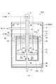
- FIG. 2 is a cross-sectional view showing a coagulation sedimentation tank of the coagulation sedimentation system according to an embodiment of the present invention.
- the coagulation sedimentation system according to the present embodiment has a coagulation sedimentation tank called a “sludge blanket type”.
- the sludge blanket type coagulation sedimentation tank forms a fluidized bed of coagulated flocs by the rising water flow in the tank and allows newly generated flocs to pass through the fluidized bed. At this time, the small flocs are captured by the large flocs in the fluidized bed and become large, and the sedimentation speed increases.
- the inflow water to the sludge blanket type coagulation sedimentation tank is separated into treated water and sludge, and each is discharged out of the tank.
- the floc is sometimes referred to as agglomerated floc, sludge, or solid matter.
- the coagulation sedimentation system 100A includes a first reaction tank 10, a second reaction tank 20, and a coagulation sedimentation tank 30A connected in this order, and from the sludge blanket part S of the coagulation sedimentation tank 30A.
- a return line L1 for returning the extracted sludge to the first reaction tank 10 a discharge line L2 for discharging sludge from the coagulation sedimentation tank 30A, a storage tank 50 connected to the discharge line L2, and a rear stage of the storage tank
- the dehydrator 60 is provided.
- the inorganic flocculant is added by the inorganic flocculant adding means 11 while introducing raw water. Moreover, the sludge returned by the return line L1 flows into the 1st reaction tank 10, and these are mixed, for example by stirring with a stirrer.
- the inorganic flocculant Al-based inorganic flocculants such as sulfuric acid band and PAC, and Fe-based inorganic flocculants such as polyiron sulfate may be used.
- crystals are precipitated by adjusting the pH with an alkali such as NaOH or Ca (OH) 2 or an acid such as H 2 SO 4 or HCL, adding a Ca, Al or Fe compound, or adding an oxidizing agent or a reducing agent. You may let them.
- the crystal grows using the sludge returned from the coagulation sedimentation tank 30A as the nucleus of the crystal.
- the second reaction tank 20 introduces the treated water from the first reaction tank 10 and is added with a polymer flocculant from the polymer flocculant addition means 21 to cause an agglomeration reaction to form an aggregate floc.
- polymer flocculant for example, anionic to cationic polyacrylamide can be used.
- the coagulation sedimentation tank 30A introduces the treated water containing the coagulated floc from the second reaction tank 20, and after the coagulated floc is grown in the sludge blanket part S, the coagulated floc as a solid is separated from the treated water. .
- the separated treated water is discharged out of the tank at the upper part of the coagulation sedimentation tank 30A.
- a part of the aggregated floc is returned to the preceding stage via the return line L1, and the rest overflows from the sludge blanket part S and is discharged from the sludge concentrating part Z4 to the storage tank 50 through the discharge line L2 as concentrated sludge.
- the storage tank 50 stores the sludge discharged from the coagulation sedimentation tank 30A via the discharge line L2.
- the sludge stored in the storage tank 50 is transported to the dehydrator 60, dehydrated, and then transported out of the system.
- the coagulation sedimentation tank 30A of this embodiment will be described.
- the coagulation sedimentation tank 30 ⁇ / b> A includes a bottomed cylindrical outer wall portion 31, and further, a bottomed bottom erected so as to be concentric with the outer wall portion 31 inside the outer wall portion 31.
- a cylindrical inner wall portion 32 is provided.
- the inner wall portion 32 has a smaller diameter and a smaller height than the outer wall portion 31.
- the inner wall portion 32 is supported on the outer wall portion 31 by a gantry (not shown).
- a center shaft 40 is disposed on the axis L of the outer wall portion 31.
- a feed pipe 41 is provided outside the center shaft 40 so as to surround the center shaft 40.
- the feed pipe 41 is connected to the inflow water distribution pipe 39.
- the inflow water distribution pipe 39 penetrates the outer wall portion 31 and protrudes to the outside of the outer wall portion 31, and is connected to the second reaction tank 20.
- the inside of the inflow water distribution pipe 39 communicates with the inside of the feed pipe 41.
- the outer walls 31, the inner wall 32, the center shaft 40, and the axis of the feed pipe 41 are all the common axis L.
- the feed pipe 41 is divided into an upper part 41a and a lower part 41b in the vertical direction, and the upper part 41a and the lower part 41b are connected by a rotary joint 42 such as a labyrinth structure.
- the feed pipe 41 is connected to the inflow water distribution pipe 39 at the side surface of the upper part 41a, and the dispersion pipe 33 is provided at the lower part 41b of the feed pipe 41.
- the dispersion pipe 33 is disposed below the inner wall portion 32, and a plurality of inflow water discharge ports 33 a are formed in the dispersion pipe 33.
- the dispersion pipe 33 rotates together with the center shaft 40 with the inflow water discharge port 33a facing the bottom 32c side of the inner wall part 32.
- the lower part 41 b of the feed pipe 41 rotates together with the dispersion pipe 33.
- the upper end part of the feed pipe 41 is closed, you may open
- the center shaft 40 is connected to the bottom 32c by a rotary joint 43.
- a concentrated sludge scraper 34 is provided at the lower end of the center shaft 40. As the center shaft 40 rotates, the concentrated sludge scraper 34 also rotates.
- the concentrated sludge scraping machine 34 is provided on the bottom 31c of the outer wall 31, and scrapes the concentrated sludge accumulated on the bottom 31c of the outer wall 31 to the central portion where the discharge line L2 is provided.
- the inner region of the inner wall portion 32 functions as the sludge blanket portion S
- the cross-sectional donut-shaped region of the outer region of the inner wall portion 32 surrounded by the outer wall portion 31 functions as a sedimentation zone Z3 that settles sludge.
- the sludge blanket portion S has a flock growth zone Z1 and a separation zone Z2 formed above the flock growth zone Z1.
- a fluidized bed of coagulated flocs is formed by the upward flow of inflow water flowing into the coagulation sedimentation tank 30A.
- the separation zone Z2 performs solid-liquid separation of the aggregated floc (solid matter) and the treated water.
- the area where the concentrated sludge scraper 34 is provided functions as the sludge concentration unit Z4.
- the inner wall 32 is connected to a drawing line 35 that can draw sludge from the sludge blanket portion S.
- the extraction line 35 has an extraction port 35a provided at the end of the extraction line 35 at the bottom 32c of the inner wall 32 so that sludge containing aggregated floc and water is extracted from below the separation zone Z2 in the sludge blanket portion S. It is connected. Further, the drawing line 35 penetrates the outer wall portion 31 and the inner wall portion 32 and protrudes to the outside, and is connected to the return line L1 via the pump P.
- the return line L1 is connected to the first reaction tank 10.
- the sludge drawn from below the separation zone Z2 in the sludge blanket part S is returned to the previous stage, passes through the first reaction tank 10 and the second reaction tank 20 via the drawing line 35 and the return line L1, and again. It flows into the coagulation sedimentation tank 30A.
- the treated water containing flocs from the second reaction tank 20 is introduced into the feed pipe 41 via the inflow water distribution pipe 39.
- the inflow water introduced into the feed pipe 41 flows downward in the feed pipe 41, is divided by the dispersion pipe 33, and is ejected from the inflow water discharge port 33a.
- the inflow water supplied into the flock growth zone Z1 is supplied almost uniformly over the entire surface of the flock growth zone Z1, and a fluidized bed is formed by the upward flow of the inflow water. Small flocs contained in the inflowing water are collected in contact with the aggregated flocs in the process of rising in the fluidized bed, and grow with a large particle size. In this way, the inflowing water grows flocs while ascending the floc growth zone Z1.
- a thin virtual boundary layer K (near the interface of the sludge blanket portion S) is formed. That is, the virtual boundary layer K is formed at the boundary between the clarification part Q and the sludge blanket part S above the outer wall part 31.
- the virtual boundary layer K and the vicinity thereof are referred to as a separation zone Z2.
- flocs are held at a high concentration. Further, part of the flocs gathered in the separation zone Z2 moves to the peripheral edge of the inner wall portion 32 by the fluidized bed due to the inflowing water, and flows into the sedimentation zone Z3 by overflowing from the inner wall portion 32 along the F1 direction.
- overflow means that a large and heavy floc overflows from the separation zone Z2 to the settling zone Z3 over the inner wall portion 32.
- the treated water that has passed through the sludge blanket part S rises due to the rising flow of the inflowing water and is discharged from the upper part of the outer wall part 31 to the outside.
- the aggregated floc that has overflowed from the peripheral edge of the inner wall portion 32 along the direction F1 flows into the sedimentation zone Z3 and settles.
- the sedimentation zone Z3 sediments the aggregated floc (sludge) that has flowed in from the inner periphery of the inner wall 32.
- the specific gravity of the aggregated floc flowing in from the sludge blanket portion S is larger than that of water, it naturally settles toward the bottom portion 31 c of the outer wall portion 31.
- the aggregated floc that settles and accumulates on the bottom 31c of the outer wall portion 31 is concentrated to become concentrated sludge, which is scraped to the central portion by the rotation of the concentrated sludge scraper 34 provided in the sludge concentration portion Z4 and discharged. It is carried to the storage tank 50 by the line L2.
- a part of the sludge discharged from the discharge line L2 connected to the sludge concentration unit Z4 is returned to the preceding agglomeration reaction tank and circulated.
- the purpose is to supply seed crystals as nuclei for crystal growth to the agglomeration reactor.
- seed crystals are supplied to the agglomeration reaction tank, crystals grow using the seed crystals as nuclei, and large particles are generated. Therefore, the solid-liquid separation property between the solid matter and the treated water in the coagulating sedimentation tank is improved.
- the sludge discharged from the discharge line L2 connected to the sludge concentration unit Z4 is returned to the previous stage as in the prior art coagulation sedimentation system
- the sludge is introduced into the sludge blanket section S of the coagulation sedimentation tank.
- the rising flow velocity in the sludge blanket portion S becomes faster.
- the residence time of the introduced influent water in the sludge blanket portion S is shortened and the rising speed is increased, so that floc growth / separation is not sufficiently performed, and the quality of treated water after separation may be deteriorated. is there.
- the mixture (sludge) containing flock and water is drawn from the lower side of the separation zone Z2, and returned to the first reaction tank 10 in the previous stage.
- the ascending flow rate of the sludge blanket part S is constant regardless of the presence or absence of sludge circulation and the amount of sludge circulation. That is, without increasing the capacity of the sludge blanket part S, it is possible to grow a good coagulation floc and maintain an appropriate residence time and ascending flow rate for sedimentation separation, and to obtain clear treated water. Become. Moreover, in the sludge blanket part S, the residence time required for flocking can be secured, and the flow rate can be made uniform without increasing the ascending flow velocity, so that the quality of the treated water discharged from the sludge blanket part S is maintained well. It is possible.
- the extraction line 35 extracts sludge from the sludge blanket part S, returns it to the previous stage, and circulates it, so that the coagulation sedimentation tank 30A can be processed more smoothly without increasing the size. Water quality can be obtained.
- Examples of such a modification include a configuration in which one or more settling tanks functioning as a settling zone are provided along a part of the outer periphery of the sludge blanket tank that forms the sludge blanket section.
- the shape of the sludge blanket tank as a sludge blanket part and the shape of the sedimentation tank as a sedimentation zone can be changed suitably.
- the drawing line 35 is connected to the bottom part 32c of the inner wall part 32 which forms the sludge blanket part S of 30 A of coagulation sedimentation tanks, you may be attached to the side surface of the inner wall part 32, It suffices that it is attached at least below the separation zone Z2 of the sludge blanket portion S. In this case, it is possible to reduce the rising speed of the inflowing water in the sludge blanket part S as described in the above embodiment above the position where the drawing line 35 is attached.
- the separation of the solid substance and water in the separation zone Z2 can be performed suitably, and the coagulation sedimentation tank 30A is enlarged. Better quality of treated water can be obtained.
- the drawing line 35 when the drawing line 35 is attached to the side surface of the sludge blanket portion S, it is only necessary to provide a nozzle on the side plate of the sludge blanket portion S, so that the device structure can be simplified.
- the drawing line 35 when the drawing line 35 is connected to the bottom 32c of the sludge blanket part S, the nozzle is provided on the bottom surface of the sludge blanket part S, so the drawing line 35 is provided in the sludge concentration part Z4, and the apparatus structure becomes complicated. There is a case.
- the configuration in which the drawing line 35 is connected to the bottom portion 32c of the sludge blanket portion S can reduce the ascending speed of the entire sludge blanket portion S in the entire sludge blanket portion S, and the sludge blanket portion S is raised by returning sludge. This is preferable because it is possible to minimize the region in which the flow velocity increases.
- the pull line 35 is connected to the lower part of the sludge blanket part S from the lower part of the sludge blanket part S in terms of promoting the growth of flocs by suppressing the rising flow velocity inside the sludge blanket part S. It can be set as the structure which pulls out sludge.
- the lower part of the sludge blanket part S refers to the lower half of the sludge blanket part S in the vertical direction.
- the drawing line 35 may be provided on the bottom surface or side surface of the lower half of the sludge blanket portion S.
- the influence on the rectifying property of the fluidized bed above the extraction line 35 can be reduced, so that good treated water quality can be obtained.
- the sludge blanket part S it is possible to minimize the region where the flow velocity of the upward flow of the sludge blanket part S increases due to sludge return.
- the drawing line 35 in which one drawing port 35a is connected to the bottom 32c of the inner wall portion 32 is shown, but a drawing line 35 having a plurality of drawing ports 35a may be used.
- the plurality of extraction openings 35a may be arranged so as to surround the axis L and be uniform.
- the drawing openings 35 a can be arranged so as to be uniformly distributed on the bottom 32 c of the inner wall portion 32. In this case, since the places where the sludge is drawn out are uniformly distributed, the influence on the fluidized bed formed by the inflowing water can be suppressed.
- a coagulation sedimentation tank 30B shown in FIG. 3 will be described as a first modification of the coagulation sedimentation tank.
- the coagulation sedimentation tank 30 ⁇ / b> B has a sludge reservoir 46 provided so as to be recessed downward at the bottom 32 c of the inner wall portion 32, and the drawing line 35 is connected to the sludge reservoir 46.
- the range that affects the rectification of the fluidized bed by providing the extraction line may be the vicinity of the sludge reservoir 46.
- the sludge is concentrated in the sludge reservoir 46, and sludge having a high SS concentration can be returned to the previous stage.
- the sludge storage part 46 may be formed, for example so that the axis line L may be enclosed, and the some sludge storage part 46 may be disperse
- the sludge storage part 46 is provided so that a part of the bottom part 32 c is recessed downward.
- the sludge storage part 46 is provided outside the coagulation sedimentation tank 30 ⁇ / b> B via a pipe, and the drawing line 35 is provided.
- the sludge storage section outside the coagulation sedimentation tank 30B may be connected. According to this configuration, the sludge is concentrated in the sludge reservoir, and the sludge having a high SS concentration can be returned to the previous stage.
- a coagulation sedimentation tank 30C as shown in FIG. 4 can be used as a second modification.
- the extraction line 45 has an extraction port 45a that is inserted from the upper surface of the sludge blanket portion S without penetrating the wall of the inner wall portion 32 and is positioned below the separation zone Z2 of the sludge blanket portion S. .
- the drawing line 45 penetrates the separation zone Z2 in a substantially vertical direction, protrudes to the outside of the outer wall portion 31 above the inner wall portion 32, and is connected to the return line L1.
- the extraction line 45 penetrates the outer wall portion 31 at the upper part and protrudes outside, the water pressure in the vicinity of the penetration part is lower than that when the extraction line penetrates the outer wall part 31 at the lower part.
- the structure for sealing the penetration part of the part 31 becomes simple.
- the drawing line 45 can protrude outside the outer wall portion 31 by penetrating only the outer wall portion 31. Therefore, compared with the case where the drawing line does not penetrate the separation zone Z2 in the vertical direction and penetrates the inner wall portion 32 and the outer wall portion 31 and protrudes to the outside of the outer wall portion 31, the number of walls to be penetrated is reduced. Can be easier.
- the drawing line 45 penetrates the outer wall 31 above the inner wall 32 and protrudes outward.
- the drawing line 45 penetrates the water surface of the upper open type coagulation sedimentation tank and protrudes outward. May be.
- the drawing line 47 does not penetrate the outer wall portion 31, the configuration is simplified. Moreover, it can be set as the structure which changes the vertical position of the extraction opening 45a, and changes the extraction position of sludge.
- the extraction ports 45a may be uniformly distributed around the axis L, for example, so that the influence of extracting sludge on the rectification of the fluidized bed in the floc growth zone Z1 can be controlled.
- the extraction line 45 connected to the extraction port 45 a may be connected to a single line and protrude to the outside of the outer wall portion 31.
- the extraction line 45 may be provided so that the position of the extraction port 45a can be changed.
- the sludge extraction position can be adjusted so as not to affect the rectification of the sludge blanket portion S by providing the extraction line 45 so as to change the sludge extraction position depending on the position of the extraction port 45a. It is. Therefore, the rectification
- extraction ports 45a may be provided at a plurality of locations, and control may be performed so that the sludge extraction position is changed at regular intervals by automatic valve switching or the like.
- the number of the inflowing water dispersion pipes 33 is two, but three or more dispersion pipes extending radially with respect to the drive shaft pipe may be provided. Further, the dispersion pipe 33 is not limited to a mode orthogonal to the axis of the drive shaft pipe, and may be inclined corresponding to the shape of the bottom of the coagulation sedimentation tank.
- the configuration of the coagulation sedimentation system can be changed as appropriate.
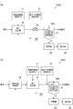
- two modified examples of the coagulation sedimentation system will be described with reference to FIGS.
- the coagulation sedimentation system 100B has a line mixer 22 instead of the second reaction tank 20 of the first embodiment.
- the line mixer 22 adds the polymer flocculant from the polymer flocculant addition means 21 to the treated water from the first reaction tank 10 and mixes the treated water and the polymer flocculant. Thereafter, the treated water mixed with the polymer flocculant flows as inflow water of the coagulation sedimentation tank 30A, and the coagulation sedimentation process is performed in the coagulation sedimentation tank 30A.
- the line mixer 22 mixes the polymer flocculant and the treated water, the reaction for forming the flocculation floc is basically performed in the sludge blanket part S of the flocculation settling tank 30A, and the flocculation floc is removed. Form.
- the polymer flocculant addition means 21 does not use the second reaction tank of the first embodiment and the polymer flocculant addition means 21 enters the polymer in the influent water distribution pipe immediately before the coagulation sedimentation tank 30A.
- the flocculant may be line injected.
- the aggregation floc is mainly formed in the sludge blanket part S of the aggregation sedimentation tank 30A.
- the coagulation sedimentation system 100 ⁇ / b> C may have an activated sludge treatment tank 70 in front of the first reaction tank 10.
- all the sludge extracted from the coagulation sedimentation tank 30A may be returned to the activated sludge treatment tank 70 and circulated, with some sludge in the activated sludge treatment tank 70 and other sludge in the first reaction. You may circulate by returning to the tank 10.
- the sludge concentration in the activated sludge treatment tank can be maintained at an appropriate concentration, and the number of bacteria in the activated sludge treatment tank can be maintained. Therefore, the activated sludge treatment tank 70 can be efficiently treated with a high treatment load.
- SYMBOLS 10 ... 1st reaction tank, 20 ... 2nd reaction tank, 30A, 30B, 30C ... Coagulation sedimentation tank, 35, 45 ... Extraction line, 46 ... Sludge storage part, 100A, 100B, 100C ... Coagulation sedimentation system, S ... Sludge Blanket section, L1 ... return line, L2 ... discharge line, Z1 ... flock growth zone, Z2 ... separation zone, Z3 ... sedimentation zone, Z4 ... sludge concentration section.
Landscapes
- Chemical & Material Sciences (AREA)
- Chemical Kinetics & Catalysis (AREA)
- General Chemical & Material Sciences (AREA)
- Life Sciences & Earth Sciences (AREA)
- Hydrology & Water Resources (AREA)
- Engineering & Computer Science (AREA)
- Environmental & Geological Engineering (AREA)
- Water Supply & Treatment (AREA)
- Organic Chemistry (AREA)
- Separation Of Suspended Particles By Flocculating Agents (AREA)
Abstract
L'invention concerne une cuve de sédimentation (30A) qui est pourvue d'au moins une partie lit de boue (S) comprenant une zone de croissance de floc (Z1) dans laquelle une couche fluidisée se forme par écoulement vers le haut de l'eau entrante et une zone de séparation (Z2) formée au-dessus de la zone de croissance de floc (Z1) pour séparer les solides et l'eau traitée, et qui est caractérisée en ce qu'elle est pourvue d'une ligne de prélèvement (35) pour retirer la boue qui se trouve en dessous de la zone de séparation (Z2) et d'une ligne d'évacuation (L2) pour évacuer la boue qui a débordé depuis la partie supérieure de la zone de séparation (Z2).
Applications Claiming Priority (2)
| Application Number | Priority Date | Filing Date | Title |
|---|---|---|---|
| JP2014058151A JP6320102B2 (ja) | 2014-03-20 | 2014-03-20 | 凝集沈殿槽及び凝集沈殿システム |
| JP2014-058151 | 2014-03-20 |
Publications (1)
| Publication Number | Publication Date |
|---|---|
| WO2015141375A1 true WO2015141375A1 (fr) | 2015-09-24 |
Family
ID=54144354
Family Applications (1)
| Application Number | Title | Priority Date | Filing Date |
|---|---|---|---|
| PCT/JP2015/054634 Ceased WO2015141375A1 (fr) | 2014-03-20 | 2015-02-19 | Cuve de sédimentation et système de sédimentation |
Country Status (3)
| Country | Link |
|---|---|
| JP (1) | JP6320102B2 (fr) |
| TW (1) | TW201536393A (fr) |
| WO (1) | WO2015141375A1 (fr) |
Cited By (5)
| Publication number | Priority date | Publication date | Assignee | Title |
|---|---|---|---|---|
| JP2018134619A (ja) * | 2017-02-24 | 2018-08-30 | オルガノ株式会社 | 凝集沈殿装置 |
| JP2018143914A (ja) * | 2017-03-01 | 2018-09-20 | オルガノ株式会社 | 凝集沈殿装置とその駆動方法 |
| JP2019063764A (ja) * | 2017-10-04 | 2019-04-25 | オルガノ株式会社 | 凝集沈殿装置とその運転方法 |
| JP2019155282A (ja) * | 2018-03-13 | 2019-09-19 | 住友重機械エンバイロメント株式会社 | 固液分離装置 |
| JP2019155284A (ja) * | 2018-03-13 | 2019-09-19 | 住友重機械エンバイロメント株式会社 | 固液分離装置 |
Families Citing this family (6)
| Publication number | Priority date | Publication date | Assignee | Title |
|---|---|---|---|---|
| WO2018155524A1 (fr) * | 2017-02-24 | 2018-08-30 | オルガノ株式会社 | Dispositif de floculation |
| CN110382074B (zh) | 2017-02-24 | 2021-08-24 | 奥加诺株式会社 | 絮凝和沉积设备 |
| JP7045881B2 (ja) * | 2017-02-24 | 2022-04-01 | オルガノ株式会社 | 凝集沈殿装置 |
| JP2020157284A (ja) * | 2019-03-28 | 2020-10-01 | 住友重機械エンバイロメント株式会社 | 凝集沈殿処理装置、凝集沈殿処理システム及び凝集沈殿処理装置の運転方法 |
| JP7327972B2 (ja) * | 2019-03-29 | 2023-08-16 | 住友重機械エンバイロメント株式会社 | 凝集沈殿処理装置及び凝集沈殿処理装置の運転方法 |
| JP7797297B2 (ja) * | 2022-04-21 | 2026-01-13 | 成和リニューアルワークス株式会社 | 濁水処理装置 |
Citations (2)
| Publication number | Priority date | Publication date | Assignee | Title |
|---|---|---|---|---|
| JPH10479A (ja) * | 1996-06-12 | 1998-01-06 | Kurita Water Ind Ltd | フッ素除去装置 |
| JP2010184179A (ja) * | 2009-02-10 | 2010-08-26 | Japan Organo Co Ltd | 凝集沈殿装置 |
-
2014
- 2014-03-20 JP JP2014058151A patent/JP6320102B2/ja active Active
-
2015
- 2015-02-16 TW TW104105342A patent/TW201536393A/zh unknown
- 2015-02-19 WO PCT/JP2015/054634 patent/WO2015141375A1/fr not_active Ceased
Patent Citations (2)
| Publication number | Priority date | Publication date | Assignee | Title |
|---|---|---|---|---|
| JPH10479A (ja) * | 1996-06-12 | 1998-01-06 | Kurita Water Ind Ltd | フッ素除去装置 |
| JP2010184179A (ja) * | 2009-02-10 | 2010-08-26 | Japan Organo Co Ltd | 凝集沈殿装置 |
Cited By (7)
| Publication number | Priority date | Publication date | Assignee | Title |
|---|---|---|---|---|
| JP2018134619A (ja) * | 2017-02-24 | 2018-08-30 | オルガノ株式会社 | 凝集沈殿装置 |
| JP2018143914A (ja) * | 2017-03-01 | 2018-09-20 | オルガノ株式会社 | 凝集沈殿装置とその駆動方法 |
| JP2019063764A (ja) * | 2017-10-04 | 2019-04-25 | オルガノ株式会社 | 凝集沈殿装置とその運転方法 |
| JP2019155282A (ja) * | 2018-03-13 | 2019-09-19 | 住友重機械エンバイロメント株式会社 | 固液分離装置 |
| JP2019155284A (ja) * | 2018-03-13 | 2019-09-19 | 住友重機械エンバイロメント株式会社 | 固液分離装置 |
| JP7052184B2 (ja) | 2018-03-13 | 2022-04-12 | 住友重機械エンバイロメント株式会社 | 固液分離装置 |
| JP7056824B2 (ja) | 2018-03-13 | 2022-04-19 | 住友重機械エンバイロメント株式会社 | 固液分離装置 |
Also Published As
| Publication number | Publication date |
|---|---|
| JP6320102B2 (ja) | 2018-05-09 |
| JP2015181975A (ja) | 2015-10-22 |
| TW201536393A (zh) | 2015-10-01 |
Similar Documents
| Publication | Publication Date | Title |
|---|---|---|
| JP6320102B2 (ja) | 凝集沈殿槽及び凝集沈殿システム | |
| DE69718494T2 (de) | Wasser- und abwasserbehandlungssystem mit innerem wiederumlauf | |
| JP5085609B2 (ja) | 凝集沈殿装置 | |
| CA2707833C (fr) | Perfectionnement apporte aux epaississeurs comportant un puits d'alimentation auto-diluant ou y etant associe | |
| JP3866439B2 (ja) | 凝集沈澱装置 | |
| CN109364575B (zh) | 一种污水处理的多级过滤系统及污水过滤方法 | |
| JP2018134619A (ja) | 凝集沈殿装置 | |
| JP6067268B2 (ja) | 水処理システム | |
| JP6626888B2 (ja) | 廃水の清澄化方法 | |
| JP5173538B2 (ja) | 水処理方法 | |
| EP3740455B1 (fr) | Procédé de récupération de phosphate d'ammonium de magnésium | |
| JP4747191B2 (ja) | 凝集沈殿装置及び凝集沈殿処理方法 | |
| JP3744699B2 (ja) | 凝集沈澱方法及び装置 | |
| JP2000117005A5 (fr) | ||
| WO2006036014A1 (fr) | Appareil de separation de coagulation | |
| JP7056824B2 (ja) | 固液分離装置 | |
| JP7327972B2 (ja) | 凝集沈殿処理装置及び凝集沈殿処理装置の運転方法 | |
| JP7052184B2 (ja) | 固液分離装置 | |
| JP5239653B2 (ja) | 加圧浮上処理方法 | |
| KR101205153B1 (ko) | 폐수의 응집 처리 장치 | |
| JP4223651B2 (ja) | 凝集沈殿装置 | |
| KR101694919B1 (ko) | 무동력 혼화응집조 및 이를 포함하는 용존공기부상장치 | |
| JP5914113B2 (ja) | 固液分離装置 | |
| JP2000334209A (ja) | 砂添加凝集沈澱装置 | |
| JP2020157284A (ja) | 凝集沈殿処理装置、凝集沈殿処理システム及び凝集沈殿処理装置の運転方法 |
Legal Events
| Date | Code | Title | Description |
|---|---|---|---|
| 121 | Ep: the epo has been informed by wipo that ep was designated in this application |
Ref document number: 15765735 Country of ref document: EP Kind code of ref document: A1 |
|
| NENP | Non-entry into the national phase |
Ref country code: DE |
|
| 122 | Ep: pct application non-entry in european phase |
Ref document number: 15765735 Country of ref document: EP Kind code of ref document: A1 |