WO2014181396A1 - Spectrometre de masse - Google Patents
Spectrometre de masse Download PDFInfo
- Publication number
- WO2014181396A1 WO2014181396A1 PCT/JP2013/062914 JP2013062914W WO2014181396A1 WO 2014181396 A1 WO2014181396 A1 WO 2014181396A1 JP 2013062914 W JP2013062914 W JP 2013062914W WO 2014181396 A1 WO2014181396 A1 WO 2014181396A1
- Authority
- WO
- WIPO (PCT)
- Prior art keywords
- voltage
- ion
- ions
- mass
- mass spectrometer
- Prior art date
- Legal status (The legal status is an assumption and is not a legal conclusion. Google has not performed a legal analysis and makes no representation as to the accuracy of the status listed.)
- Ceased
Links
Images




Classifications
-
- H—ELECTRICITY
- H01—ELECTRIC ELEMENTS
- H01J—ELECTRIC DISCHARGE TUBES OR DISCHARGE LAMPS
- H01J49/00—Particle spectrometers or separator tubes
- H01J49/02—Details
- H01J49/022—Circuit arrangements, e.g. for generating deviation currents or voltages ; Components associated with high voltage supply
-
- H—ELECTRICITY
- H01—ELECTRIC ELEMENTS
- H01J—ELECTRIC DISCHARGE TUBES OR DISCHARGE LAMPS
- H01J49/00—Particle spectrometers or separator tubes
- H01J49/0027—Methods for using particle spectrometers
- H01J49/0031—Step by step routines describing the use of the apparatus
-
- H—ELECTRICITY
- H01—ELECTRIC ELEMENTS
- H01J—ELECTRIC DISCHARGE TUBES OR DISCHARGE LAMPS
- H01J49/00—Particle spectrometers or separator tubes
- H01J49/26—Mass spectrometers or separator tubes
- H01J49/34—Dynamic spectrometers
- H01J49/42—Stability-of-path spectrometers, e.g. monopole, quadrupole, multipole, farvitrons
- H01J49/4205—Device types
- H01J49/421—Mass filters, i.e. deviating unwanted ions without trapping
- H01J49/4215—Quadrupole mass filters
Definitions
- the present invention relates to a mass spectrometer.
- a mass spectrometer using an atmospheric pressure ion source capable of directly ionizing a liquid sample is generally used.
- mass spectrometry such as a quadrupole mass filter disposed in an analysis chamber maintained in a high vacuum atmosphere. It is done by a vessel.
- one or a plurality of intermediate vacuum chambers having a stepwise increase in the degree of vacuum are provided between the ionization chamber, which is an atmospheric pressure atmosphere, and the analysis chamber (that is, Thus, ions are transported through small-diameter ion passage holes formed in partition walls separating adjacent chambers.
- each intermediate vacuum chamber is provided with an ion transport optical system called an ion lens or an ion guide that converges ions or accelerates or decelerates them depending on the action of an electric field. It has been.
- a sampling cone or a skimmer having an ion passage hole formed in a partition wall that separates the chambers at the top also converges, accelerates or decelerates ions by an electric field formed by an appropriate voltage applied. It can be said that it is a kind of ion transport optical system.
- a quadrupole mass filter disposed in the analysis chamber and a prefilter provided in the preceding stage are also a kind of ion transport optical system.
- the mass spectrometer includes a plurality of ion transport optical systems that affect the flight trajectory of ions by the action of an electric field.
- the intermediate vacuum chamber or the analysis It is introduced into the room.
- unwanted particles often adhere to and deposit on the ion transport optics described above.
- dirt or foreign matter adheres to the surface of the ion transport optical system and an insulating film is formed, it becomes easy to charge up (charge) when ions collide with the surface (see Patent Document 1, etc.).
- quadrupole mass filters, ion guides, etc. are fixed at predetermined positions in the space by being held by a structure made of an insulating material such as ceramic or synthetic resin.
- FIG. 4 (a) is a chromatogram showing the detection results of ions for a sample when a standard sample is repeatedly introduced at predetermined time intervals in LCMS using a quadrupole mass spectrometer.
- the peak in the figure is an ion peak derived from a standard sample. If it is originally, the peak intensity should not change, but the peak intensity decreases as time passes, that is, as the measurement is repeated. I understand. According to the experiment by the present inventor, it can be estimated that this decrease in ionic strength is mainly due to charge-up of the quadrupole mass filter.
- the present invention has been made to solve the above-mentioned problems, and the object of the present invention is to prevent or reduce the ionic strength over time by preventing or reducing the charge-up of the ion transport optical system.
- An object of the present invention is to provide a mass spectrometer capable of reducing and performing highly sensitive analysis.
- an appropriate high-frequency voltage or DC voltage is applied to the ion transport optical system provided in the mass spectrometer in order to converge ions or in some cases accelerate or decelerate, and the voltage value is Usually, it is set so as to be optimal or close to the mass-to-charge ratio or mass-to-charge ratio range of the ion to be measured at that time.
- a cycle of sequentially executing detection for ions having a predetermined mass-to-charge ratio is repeated, and at this time, the voltage applied to the ion transport optical system is also switched sequentially.
- Such voltage switching cannot be performed instantaneously, and it takes some time for the voltage after switching to settle. Therefore, in general, a period (pause time) for prohibiting the capture of detection data is provided before the period (dwell time: Dwell time) for capturing detection data such as ion intensity, and the pause time is set to voltage.
- the amount of time required to settle is secured.
- the inventor of the present application pays attention to the fact that no data is collected during the pause time and that the pause time is surely provided at a high frequency, and the operation for eliminating or reducing the charge-up is pause time.
- the present invention was conceived to be carried out during the present invention.
- the first aspect of the present invention made to solve the above problems has one or more ion transport optical systems for transporting ions by the action of an electric field between the ion source and the ion detector.
- a mass spectrometer that performs SIM measurement or MRM measurement that repeats a cycle in which mass analysis is sequentially performed on ions having a plurality of mass-to-charge ratios specified in advance
- the detection data is collected by the ion detector as the mass-to-charge ratio is switched.
- a control unit for controlling the voltage generation unit to temporarily apply a small DC voltage It is characterized by having.
- the “ion transport optical system” includes all elements that converge, diverge, accelerate, or decelerate ions by the action of a DC electric field, a high-frequency electric field, or an electric field superimposed thereon.
- a device usually called an ion lens or an ion guide, a skimmer having an ion passage hole, a sampling cone or an aperture electrode, or a quadrupole mass filter or a pre-quadruplex provided in the preceding stage. It also includes a polar mass filter.
- the control unit switches the DC voltage applied to the at least one ion transport optical system during the pause time, and the DC voltage before and after the switching.
- the voltage generator can be controlled to temporarily apply a DC voltage having a different polarity.
- the polarity of the DC voltage applied from the voltage generator to the ion transport optical system is temporarily reversed during the pause time under the control of the controller, the polarity of the voltage is determined by the ion transport optics. It has the same polarity as the electric charge accumulated on the surface of an undesired insulating film formed on the surface of the system or an insulating support structure holding the ion transport optical system. For this reason, the charges accumulated on the surface and the charges existing in the vicinity of the surface are dispersed by the electrostatic repulsive force, and the charge-up is eliminated.
- the pause time appears at a relatively short time interval, and the charge-up is canceled at each pause time, so that the ion intensity is hardly lowered due to the charge-up during the measurement.
- ions hardly pass through the ion transport optical system (substantially hardly pass through). .
- ions hardly reach the subsequent stage of the ion transport optical system, and charge-up of the subsequent ion transport optical system itself or an insulating support structure that holds the ion transport optical system is reduced.
- the polarity of the DC voltage applied from the voltage generator to the ion transport optical system during the pause time is not reversed, but the polarity is the same as that of the DC voltage before and after the pause time, and the absolute value is greater than either of them.
- a small DC voltage is temporarily applied, although the above-described discrete effect of charge due to electrostatic repulsion cannot be obtained, ions are difficult to pass through the ion transport optical system. Charge-up of the ion transport optical system itself or an insulating support structure that holds the ion transport optical system itself can be reduced.
- the control unit changes the time for temporarily applying DC voltages having different polarities according to the length of the pause time. Good.
- a second aspect according to the present invention for solving the above problems is a mass having one or more ion transport optical systems for transporting ions by the action of an electric field between an ion source and an ion detector.
- a mass spectrometer that performs SIM measurement or MRM measurement that repeats a cycle of sequentially performing mass analysis on ions having a plurality of mass-to-charge ratios specified in advance
- a) a voltage generator that applies a high-frequency voltage having an amplitude corresponding to a mass-to-charge ratio of ions to be measured to at least one of the ion transport optical systems in the SIM measurement or MRM measurement
- a high-frequency voltage applied to the at least one ion transport optical system during a pause time during which collection of detection data by the ion detector is paused as the mass-to-charge ratio of ions to be measured is switched in SIM measurement or MRM measurement.
- a controller that controls the voltage generator to temporarily change the amplitude to an amplitude that does not have a focusing
- the mass spectrometer of the second aspect typically and preferably, a configuration in which the high-frequency voltage applied to the at least one ion transport optical system is temporarily stopped (the amplitude is made zero) during the pause time; Good.
- ions are likely to accumulate in the vicinity of a region having a potential difference, which tends to come into contact with the ion transport optical system on the rear side and its support structure to cause charge-up.
- the mass spectrometer of the second aspect is configured to change the time for temporarily changing to an amplitude that does not have a converging effect on ions according to the length of the pause time. It is good to do. As a result, when the pause time is short, it is possible to minimize the decrease in sensitivity due to the delay in the rise of the ion intensity by shortening the time for temporarily changing to an amplitude that does not have a focusing effect on ions. And charge-up can be eliminated. On the other hand, when the pause time is long, the effect of eliminating the charge-up can be sufficiently exhibited by lengthening the time for temporarily changing to an amplitude that does not have a focusing action on ions.
- the mass spectrometer according to the present invention can eliminate or reduce charge-up of the ion transport optical system itself or a support structure holding the ion transport optical system during the execution of SIM measurement or MRM measurement. Accordingly, it is possible to avoid a decrease in the amount of ions passing due to charge-up, thereby preventing a decrease in detection sensitivity and accuracy over time and achieving a highly sensitive and highly accurate analysis.
- the schematic block diagram of the principal part of the quadrupole-type mass spectrometer by one Example of this invention The schematic diagram which shows the measurement sequence in the case of SIM measurement (temporal change of the voltage applied to a pre quadrupole mass filter).
- the timing diagram explaining the difference of the applied voltage during the pause time of the apparatus of a present Example, and the conventional apparatus.
- the chromatogram which shows the actual measurement result of the ionic strength change with respect to time in the conventional apparatus (without DC voltage polarity reversal) and the apparatus of the present embodiment (with DC voltage polarity reversal).
- FIG. 1 is a configuration diagram of a main part of the quadrupole mass spectrometer according to the present embodiment.
- the quadrupole mass spectrometer includes an ionization chamber 2 for ionizing a compound in a sample under a substantially atmospheric pressure, and an ion for mass spectrometry and detection. And a first intermediate vacuum chamber 3 and a second intermediate vacuum chamber 4 whose degree of vacuum is increased stepwise between the ionization chamber 2 and the analysis chamber 5. .
- An electrospray ionization (ESI) probe 6 is arranged in the ionization chamber 2 to ionize a compound in the sample by electrostatic spraying of a liquid sample.
- an ion lens 8 and a multipole ion guide 10 that transport ions while converging by the action of a high-frequency electric field are arranged.
- a pre-quadrupole mass filter 12, a main quadrupole mass filter 13, and an ion detector 14 are arranged along the ion optical axis C.
- the ion lens 8 has a configuration in which a plurality (for example, four) of virtual rod electrodes arranged in a row at a predetermined interval in the direction of the ion optical axis C are arranged around the ion optical axis C.
- the multipole ion guide 10 has a configuration in which a plurality (for example, eight) of rod electrodes extending in the direction of the ion optical axis C are arranged around the ion optical axis C.
- Each of the pre-quadrupole mass filter 12 and the main quadrupole mass filter 13 has a configuration in which four rod electrodes extending in the direction of the ion optical axis C are arranged around the ion optical axis C.
- the former is compared with the latter.
- the rod electrode is shortened.
- the ionization chamber 2 and the first intermediate vacuum chamber 3 communicate with each other through a heating capillary 7 heated to an appropriate temperature, and the first intermediate vacuum chamber 3 and the second intermediate vacuum chamber 4 are formed at the top of the skimmer 9.
- the second intermediate vacuum chamber 4 and the analysis chamber 5 communicate with each other through a minute ion passage hole formed in the aperture electrode 11.
- Each of the ion lens 8, skimmer 9, multipole ion guide 10, aperture electrode 11, pre-quadrupole mass filter 12, and main quadrupole mass filter 13 arranged along the ion optical axis C includes a power supply unit 21.
- a voltage obtained by adding a DC voltage or a high-frequency voltage and a DC voltage is applied from .about.26. All of these are ions that converge or diverge by the action of an electric field (high-frequency electric field or DC electric field) or accelerate or decelerate ions, that is, transport ions while controlling the behavior of ions. It can be said that this is an ion transport optical system.
- an appropriate voltage is also applied to the heating capillary 7 and the like.
- the operations of the power supply units 21 to 26 are controlled by the analysis control unit 30.
- the analysis control unit 30 includes a measurement sequence determination unit 31 and a measurement parameter storage unit 32 as functional blocks responsible for operations characteristic of the apparatus of this embodiment.
- the data processing unit 35 receives the detection signal obtained by the ion detector 14 and creates, for example, a mass spectrum, a mass chromatogram, a total ion chromatogram, etc., or qualifies unknown compounds and quantifies target compounds.
- the control unit 36 is responsible for system control higher than the analysis control unit 30 and a user interface through the input unit 37 and the display unit 38.
- control unit 36 In general, at least a part of the control unit 36, the data processing unit 35, and the analysis control unit 30 uses a personal computer as a hardware resource, and executes dedicated control / processing software installed in the computer in advance. Thus, a configuration for realizing each function can be realized.
- a general mass spectrometry operation in the quadrupole mass spectrometer of the present embodiment will be schematically described.
- a sample solution eluted from a column of a liquid chromatograph (not shown) is introduced into the electrospray ionization probe 6, the sample solution is charged at the tip of the probe 6 and sprayed into the ionization chamber 2 as fine droplets. Is done. The charged droplet contacts the surrounding air and becomes finer, and the solvent in the droplet evaporates. In the process, the sample component in the droplet is charged, and ions are generated.
- An air flow that flows from the ionization chamber 2 side to the first intermediate vacuum chamber 3 is formed by the differential pressure between both end faces of the heating capillary 7.
- the generated ions are sucked into the heating capillary 7 and sent into the first intermediate vacuum chamber 3.
- the ions derived from the sample are converged by the ion lens 8 and sent to the second intermediate vacuum chamber 4 through the ion passage hole at the top of the skimmer 9. Further, the light is converged by the ion guide 10 and sent to the analysis chamber 5 through an ion passage hole formed in the aperture electrode 11.
- sample-derived ions are introduced into the main quadrupole mass filter 13 through the pre-quadrupole mass filter 12.
- a voltage obtained by superimposing a high-frequency voltage on a DC voltage is applied from the power supply unit 26 to the rod electrode of the main quadrupole mass filter 13, and only ions having a specific mass-to-charge ratio corresponding to the voltage are supplied to the main quadrupole. It passes through the polar mass filter 13 and reaches the ion detector 14.
- the ion detector 14 generates an ion intensity signal corresponding to the amount of ions that have reached, and the data processing unit 35 processes detection data obtained by digitizing the ion intensity signal.
- scan measurement, SIM measurement, and the like can be selectively performed in accordance with user (operator) input settings, as in a general apparatus.
- SIM measurement in addition to the mass-to-charge ratio that the user wants to measure at the same time, the dwell time for capturing detection data per ion and the voltage applied to the main quadrupole mass filter 13 or the like to switch the mass-to-charge ratio of the measurement object Input and set the pause time for switching.
- the dwell time is automatically calculated from the cycle time and the number of channels.
- pause time may be calculated. That is, the dwell time and pause time are not necessarily input by the user, and can be automatically calculated from other measurement parameters.
- FIG. 2 is a schematic diagram showing an example of a temporal change in the voltage applied to the pre-quadrupole mass filter, which is set as a measurement sequence during SIM measurement.
- M1, M2, and M3 that is, the number of channels is 3.
- detection data indicating the intensity of ions having a mass-to-charge ratio of M1, M2, or M3 is acquired during one dwell time, and measurement is performed, for example, during a pause time sandwiched between two dwell times.
- the voltage is switched to change the target mass-to-charge ratio from M1 to M2 or from M2 to M3.
- the pause time is determined with a certain margin.
- FIG. 3 is a timing chart for explaining the difference in applied voltage during the pause time between the apparatus of this embodiment and the conventional apparatus. This shows a change in DC voltage (DC bias voltage) applied to the pre-quadrupole mass filter 12 when the measurement target ions are positive ions.
- the optimum DC voltage for measuring ions in a certain channel is -V1
- the optimum DC voltage for measuring ions in the next channel is -V2. Therefore, in the conventional apparatus, the DC voltage applied to the pre-quadrupole mass filter 12 is changed from ⁇ V1 to ⁇ V2 during the pause time until the next dwell time starts after the dwell time for the previous channel ends. Switch. In contrast, in the apparatus of the present embodiment, the DC voltage applied to the pre-quadrupole mass filter 12 during the pause time until the next dwell time starts after the dwell time for the previous channel ends is ⁇ The value is changed from V1 to + V1 which is the same and the polarity is inverted, and then switched to -V2.
- the polarity of the DC voltage applied to the pre-quadrupole mass filter 12 is temporarily reversed during the pause time, the polarity is changed to the surface of the rod electrode of the pre-quadrupole mass filter 12 (strictly speaking, Insulating film formed on the surface of the insulating structure and the surface of the insulating structure holding the pre-quadrupole mass filter 12 have the same polarity as the electric charge accumulated (or present near the surface). As a result, the accumulated charge is dispersed and charge-up is eliminated.
- the polarity of the DC voltage applied to the pre-quadrupole mass filter 12 is temporarily reversed, ions hardly pass through the pre-quadrupole mass filter 12 due to the action of the electric field formed thereby.
- the amount of ions reaching the quadrupole mass filter 13 is greatly reduced (substantially becomes substantially zero), and the surface of the rod electrode of the main quadrupole mass filter 13 and the main quadrupole mass filter 13 are held. Charge up on the surface of the insulating structure is reduced.
- FIG. 4 (a) is a chromatogram showing actual measurement results of changes in ion intensity over time in a conventional apparatus (without DC voltage polarity reversal)
- FIG. 4 (b) is as shown in FIG.
- FIG. 6 is a chromatogram showing actual measurement results of changes in ionic strength over time in the apparatus of the present example in which the polarity of the DC voltage was reversed during the pause time. If the polarity of the DC voltage is not reversed during the pause time, the ion intensity clearly decreases as the measurement is repeated. However, if the polarity of the DC voltage is reversed during the pause time, there is almost no decrease in the ion strength. . This can be presumed to be because charge-up in the vicinity of the pre-quadrupole mass filter 12 and the main quadrupole mass filter 13 has been eliminated by polarity inversion of the DC voltage to the pre-quadrupole mass filter 12.
- the pause time is originally a period provided to switch the voltage in response to the switching of the mass-to-charge ratio. If the voltage polarity inversion time is too long, the voltage after switching is sufficiently settled during the pause time. For example, the measurement target ions may not sufficiently pass through the pre-quadrupole mass filter 12 and the main quadrupole mass filter 13 even if the next dwell time is entered.
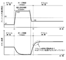
- FIG. 5 is a diagram showing changes in applied voltage and changes in ion intensity when the pause time is 1 [ms] and the voltage polarity inversion time is 0.8 [ms].
- FIG. 6 is a diagram showing changes in applied voltage and changes in ion intensity when the pause time is 1 [ms] and the voltage polarity reversal time is 1/2 [0.4] ms in FIG. It is.
- the measurement parameter storage unit 32 holds a table 32a storing optimum voltage polarity inversion times for each of a plurality of settable pause times.
- the optimum voltage polarity reversal time for each pause time may be stored in the measurement parameter storage unit 32 before the device is shipped by, for example, experimentally examining the device manufacturer in advance.
- the measurement sequence determination unit 31 refers to the table 32a stored in the measurement parameter storage unit 32 and sets the pause time. Determine the corresponding optimal voltage polarity reversal time. For example, when the pause time is 1 [ms], the voltage polarity inversion time may be determined as 0.4 [ms]. Then, the measurement sequence determination unit 31 obtains a voltage (for example, ⁇ V1, ⁇ V2, etc. in the examples of FIGS. 3 and 6) according to the mass-to-charge ratio of the measurement object in the SIM measurement, and the dwell time, pause time, cycle A measurement sequence representing a voltage change with the passage of time in one cycle is determined from time or the like.
- a voltage for example, ⁇ V1, ⁇ V2, etc. in the examples of FIGS. 3 and 6
- the measurement sequence is determined in the same manner for the applied voltages other than the pre-quadrupole mass filter 12. Then, at the time of measurement execution, the analysis control unit 30 controls the power supply units 21 to 26 according to the determined measurement sequence, and each power supply unit 21 to 26 applies a voltage to the ion transport optical system including the pre-quadrupole mass filter 12. To do.
- FIG. 7 is a diagram showing changes in applied voltage and ionic strength when the pause time is as long as 5 [ms] and the DC voltage polarity reversal time is 4 [ms].
- the DC voltage polarity reversal time is extended within the range where there is no delay in the rise of ionic strength when the pause time is long, the charge disappears more reliably during the voltage polarity reversal time, thus eliminating the charge-up. It is more effective to do.
- the voltage value (absolute value) of the DC voltage is simply smaller than the voltage value (absolute value) of the DC voltage at the dwell time before and after the pause time. You may do it.
- the voltage applied to the ion transport optical system remains opposite to the polarity of the ions, there is no effect of separating the charged charge, but the pre-quadrupole mass filter 12 is used during the pause time. Therefore, as in the case where the application of a high-frequency voltage to be described later is stopped, charge-up of the ion transport optical system in the subsequent stage, that is, the main quadrupole mass filter 13 and its support structure is reduced. be able to.
- an ion transport optical system to which a high-frequency voltage is applied mainly for focusing ions (in some cases diverging unnecessary ions) is arranged at a later stage than the ion transport optical system.
- the amplitude of the high-frequency voltage is temporarily made zero during the pause time (that is, the application of the high-frequency voltage is stopped), and the ion is substantially converged. The amplitude may be reduced to such an extent that the action is lost.
- the pre-quadrupole mass filter 12 is applied to the main quadrupole mass filter 13 in the subsequent stage in addition to the DC voltage.
- the same high frequency voltage is applied. Therefore, as shown in FIG. 8, the application of the high-frequency voltage is stopped during the pause time and during the stop time corresponding to the voltage polarity inversion time in the above embodiment. Then, the ion converging action in the space in the pre-quadrupole mass filter 12 is lost, and the ions diverge, so that the ions do not pass through the pre-quadrupole mass filter 12.
- the pre-quadrupole mass filter 12 there is a direct current potential difference between the pre-quadrupole mass filter 12 and the main quadrupole mass filter 13, and a quadrupole high-frequency electric field is formed by the pre-quadrupole mass filter 12. Because of the restraint by the electric field, ions are likely to accumulate at the potential step, which is likely to come into contact with the support structure of the main quadrupole mass filter 13 and cause charge-up. On the other hand, if the application of the high-frequency voltage to the pre-quadrupole mass filter 12 is stopped as described above and the restriction due to the electric field is removed, ions at the potential step easily move and the density decreases. Therefore, the charge-up of the support structure of the main quadrupole mass filter 13 is reduced.
- this invention is a tandem quadrupole-type mass provided with the quadrupole mass filter on both sides of the collision cell. It can also be applied to an analyzer.
Landscapes
- Chemical & Material Sciences (AREA)
- Analytical Chemistry (AREA)
- Other Investigation Or Analysis Of Materials By Electrical Means (AREA)
- Electron Tubes For Measurement (AREA)
Abstract
Priority Applications (5)
| Application Number | Priority Date | Filing Date | Title |
|---|---|---|---|
| US14/889,605 US9373487B2 (en) | 2013-05-08 | 2013-05-08 | Mass spectrometer |
| JP2015515666A JP6004098B2 (ja) | 2013-05-08 | 2013-05-08 | 質量分析装置 |
| PCT/JP2013/062914 WO2014181396A1 (fr) | 2013-05-08 | 2013-05-08 | Spectrometre de masse |
| CN201380076420.1A CN105190831B (zh) | 2013-05-08 | 2013-05-08 | 质谱仪 |
| EP13884333.9A EP2988317B1 (fr) | 2013-05-08 | 2013-05-08 | Spectrometre de masse |
Applications Claiming Priority (1)
| Application Number | Priority Date | Filing Date | Title |
|---|---|---|---|
| PCT/JP2013/062914 WO2014181396A1 (fr) | 2013-05-08 | 2013-05-08 | Spectrometre de masse |
Publications (1)
| Publication Number | Publication Date |
|---|---|
| WO2014181396A1 true WO2014181396A1 (fr) | 2014-11-13 |
Family
ID=51866901
Family Applications (1)
| Application Number | Title | Priority Date | Filing Date |
|---|---|---|---|
| PCT/JP2013/062914 Ceased WO2014181396A1 (fr) | 2013-05-08 | 2013-05-08 | Spectrometre de masse |
Country Status (5)
| Country | Link |
|---|---|
| US (1) | US9373487B2 (fr) |
| EP (1) | EP2988317B1 (fr) |
| JP (1) | JP6004098B2 (fr) |
| CN (1) | CN105190831B (fr) |
| WO (1) | WO2014181396A1 (fr) |
Cited By (13)
| Publication number | Priority date | Publication date | Assignee | Title |
|---|---|---|---|---|
| CN105225916A (zh) * | 2015-09-02 | 2016-01-06 | 上海新漫传感技术研究发展有限公司 | 实现单管离子迁移谱仪同时检测正负离子的高压电源 |
| CN105826156A (zh) * | 2015-01-27 | 2016-08-03 | 株式会社岛津制作所 | 控制dc电源的方法 |
| JP2017054737A (ja) * | 2015-09-10 | 2017-03-16 | 株式会社東芝 | 質量分析装置および質量分析方法 |
| CN106548920A (zh) * | 2015-09-17 | 2017-03-29 | 塞莫费雪科学(不来梅)有限公司 | 质谱仪 |
| WO2019229954A1 (fr) * | 2018-05-31 | 2019-12-05 | 株式会社島津製作所 | Dispositif de spectrométrie de masse |
| WO2019229945A1 (fr) * | 2018-05-31 | 2019-12-05 | 株式会社島津製作所 | Dispositif de spectrométrie de masse |
| WO2019229942A1 (fr) * | 2018-05-31 | 2019-12-05 | 株式会社島津製作所 | Dispositif de spectrométrie de masse à temps de vol |
| JP2020177912A (ja) * | 2019-04-15 | 2020-10-29 | サーモ フィッシャー サイエンティフィック (ブレーメン) ゲーエムベーハー | 向上した四重極の堅牢性を有する質量分析計 |
| JP2021077444A (ja) * | 2019-11-05 | 2021-05-20 | 株式会社島津製作所 | 質量分析装置 |
| WO2023089895A1 (fr) * | 2021-11-16 | 2023-05-25 | 株式会社島津製作所 | Dispositif de spectrométrie de masse et son procédé de commande |
| WO2023105912A1 (fr) * | 2021-12-10 | 2023-06-15 | 株式会社日立ハイテク | Procédé de commande de spectromètre de masse, et spectromètre de masse |
| JP7535673B1 (ja) | 2022-08-09 | 2024-08-16 | 南京品生医療科技有限公司 | トリプル四重極質量分析計の給電装置 |
| WO2025154225A1 (fr) * | 2024-01-18 | 2025-07-24 | 株式会社島津製作所 | Spectromètre de masse et procédé de commande de spectromètre de masse |
Families Citing this family (12)
| Publication number | Priority date | Publication date | Assignee | Title |
|---|---|---|---|---|
| US10229822B2 (en) * | 2014-10-20 | 2019-03-12 | Shimadzu Corporation | Mass spectrometer with high-voltage power source |
| US10229823B2 (en) * | 2015-08-06 | 2019-03-12 | Shimadzu Corporation | Mass spectrometer |
| US9741552B2 (en) * | 2015-12-22 | 2017-08-22 | Bruker Daltonics, Inc. | Triple quadrupole mass spectrometry coupled to trapped ion mobility separation |
| US10475635B2 (en) * | 2016-03-18 | 2019-11-12 | Shimadzu Corporation | Voltage application method, voltage application device, and time-of-flight mass spectrometer |
| CN110720133B (zh) * | 2017-06-29 | 2022-05-06 | 株式会社岛津制作所 | 四极杆质谱分析装置 |
| GB201710691D0 (en) * | 2017-07-04 | 2017-08-16 | Ge Healthcare Bio Sciences Ab | Method in bioprocess purification system |
| JP6954465B2 (ja) | 2018-06-01 | 2021-10-27 | 株式会社島津製作所 | 四重極マスフィルタおよび分析装置 |
| CN112640034B (zh) * | 2018-09-06 | 2024-10-11 | 株式会社岛津制作所 | 四极质量分析装置 |
| GB201907332D0 (en) | 2019-05-24 | 2019-07-10 | Micromass Ltd | Mass filter having reduced contamination |
| GB202013325D0 (en) * | 2020-08-26 | 2020-10-07 | Micromass Ltd | System for determining the cleanliness of mass spectrometer ion optics |
| JP7480364B2 (ja) * | 2021-01-22 | 2024-05-09 | 株式会社日立ハイテク | 質量分析装置とその制御方法 |
| GB202105778D0 (en) * | 2021-04-23 | 2021-06-09 | Micromass Ltd | Method to reduce measurement bias |
Citations (3)
| Publication number | Priority date | Publication date | Assignee | Title |
|---|---|---|---|---|
| JPH087830A (ja) | 1994-06-24 | 1996-01-12 | Shimadzu Corp | 大気圧イオン化質量分析装置 |
| JP2002117802A (ja) * | 2000-10-10 | 2002-04-19 | Jeol Ltd | 垂直加速型飛行時間型質量分析装置 |
| JP2004362982A (ja) * | 2003-06-05 | 2004-12-24 | Jeol Ltd | 飛行時間型質量分析装置 |
Family Cites Families (7)
| Publication number | Priority date | Publication date | Assignee | Title |
|---|---|---|---|---|
| US4885500A (en) * | 1986-11-19 | 1989-12-05 | Hewlett-Packard Company | Quartz quadrupole for mass filter |
| GB8703012D0 (en) * | 1987-02-10 | 1987-03-18 | Vg Instr Group | Secondary ion mass spectrometer |
| US5298745A (en) * | 1992-12-02 | 1994-03-29 | Hewlett-Packard Company | Multilayer multipole |
| WO2009095952A1 (fr) * | 2008-01-30 | 2009-08-06 | Shimadzu Corporation | Spectromètre de masse tandem |
| JP5083160B2 (ja) * | 2008-10-06 | 2012-11-28 | 株式会社島津製作所 | 四重極型質量分析装置 |
| WO2011125218A1 (fr) * | 2010-04-09 | 2011-10-13 | 株式会社島津製作所 | Dispositif d'analyse de masse quadripolaire |
| US8969797B2 (en) * | 2012-10-28 | 2015-03-03 | Shimadzu Corporation | MS/MS type mass spectrometer |
-
2013
- 2013-05-08 EP EP13884333.9A patent/EP2988317B1/fr active Active
- 2013-05-08 CN CN201380076420.1A patent/CN105190831B/zh active Active
- 2013-05-08 WO PCT/JP2013/062914 patent/WO2014181396A1/fr not_active Ceased
- 2013-05-08 JP JP2015515666A patent/JP6004098B2/ja active Active
- 2013-05-08 US US14/889,605 patent/US9373487B2/en active Active
Patent Citations (3)
| Publication number | Priority date | Publication date | Assignee | Title |
|---|---|---|---|---|
| JPH087830A (ja) | 1994-06-24 | 1996-01-12 | Shimadzu Corp | 大気圧イオン化質量分析装置 |
| JP2002117802A (ja) * | 2000-10-10 | 2002-04-19 | Jeol Ltd | 垂直加速型飛行時間型質量分析装置 |
| JP2004362982A (ja) * | 2003-06-05 | 2004-12-24 | Jeol Ltd | 飛行時間型質量分析装置 |
Non-Patent Citations (1)
| Title |
|---|
| See also references of EP2988317A4 |
Cited By (33)
| Publication number | Priority date | Publication date | Assignee | Title |
|---|---|---|---|---|
| CN105826156A (zh) * | 2015-01-27 | 2016-08-03 | 株式会社岛津制作所 | 控制dc电源的方法 |
| EP3054474A1 (fr) * | 2015-01-27 | 2016-08-10 | Shimadzu Corporation | Procédé de commande d'une alimentation en courant continu |
| US9892897B2 (en) | 2015-01-27 | 2018-02-13 | Shimadzu Corporation | Method of controlling a DC power supply |
| CN105826156B (zh) * | 2015-01-27 | 2018-07-06 | 株式会社岛津制作所 | 控制dc电源的方法 |
| CN105225916B (zh) * | 2015-09-02 | 2017-06-23 | 上海新漫传感技术研究发展有限公司 | 实现单管离子迁移谱仪同时检测正负离子高压电源及方法 |
| CN105225916A (zh) * | 2015-09-02 | 2016-01-06 | 上海新漫传感技术研究发展有限公司 | 实现单管离子迁移谱仪同时检测正负离子的高压电源 |
| JP2017054737A (ja) * | 2015-09-10 | 2017-03-16 | 株式会社東芝 | 質量分析装置および質量分析方法 |
| US10665438B2 (en) | 2015-09-17 | 2020-05-26 | Thermo Fisher Scientific (Bremen) Gmbh | Elemental mass spectrometer |
| CN106548920A (zh) * | 2015-09-17 | 2017-03-29 | 塞莫费雪科学(不来梅)有限公司 | 质谱仪 |
| GB2544959A (en) * | 2015-09-17 | 2017-06-07 | Thermo Fisher Scient (Bremen) Gmbh | Mass spectrometer |
| GB2544959B (en) * | 2015-09-17 | 2019-06-05 | Thermo Fisher Scient Bremen Gmbh | Mass spectrometer |
| US11189473B2 (en) | 2015-09-17 | 2021-11-30 | Thermo Fisher Scientific (Bremen) Gmbh | Mass spectrometer |
| JPWO2019229945A1 (ja) * | 2018-05-31 | 2021-03-11 | 株式会社島津製作所 | 質量分析装置 |
| US11869759B2 (en) | 2018-05-31 | 2024-01-09 | Shimadzu Corporation | Mass spectrometer |
| JPWO2019229942A1 (ja) * | 2018-05-31 | 2021-01-07 | 株式会社島津製作所 | 飛行時間型質量分析装置 |
| WO2019229945A1 (fr) * | 2018-05-31 | 2019-12-05 | 株式会社島津製作所 | Dispositif de spectrométrie de masse |
| JPWO2019229954A1 (ja) * | 2018-05-31 | 2021-04-08 | 株式会社島津製作所 | 質量分析装置 |
| WO2019229954A1 (fr) * | 2018-05-31 | 2019-12-05 | 株式会社島津製作所 | Dispositif de spectrométrie de masse |
| US11239069B2 (en) | 2018-05-31 | 2022-02-01 | Shimadzu Corporation | Mass spectrometer |
| WO2019229942A1 (fr) * | 2018-05-31 | 2019-12-05 | 株式会社島津製作所 | Dispositif de spectrométrie de masse à temps de vol |
| JP2020177912A (ja) * | 2019-04-15 | 2020-10-29 | サーモ フィッシャー サイエンティフィック (ブレーメン) ゲーエムベーハー | 向上した四重極の堅牢性を有する質量分析計 |
| JP7053711B2 (ja) | 2019-04-15 | 2022-04-12 | サーモ フィッシャー サイエンティフィック (ブレーメン) ゲーエムベーハー | 向上した四重極の堅牢性を有する質量分析計及び質量分析計を操作する方法 |
| JP2021077444A (ja) * | 2019-11-05 | 2021-05-20 | 株式会社島津製作所 | 質量分析装置 |
| JP7207266B2 (ja) | 2019-11-05 | 2023-01-18 | 株式会社島津製作所 | 質量分析装置 |
| WO2023089895A1 (fr) * | 2021-11-16 | 2023-05-25 | 株式会社島津製作所 | Dispositif de spectrométrie de masse et son procédé de commande |
| JPWO2023089895A1 (fr) * | 2021-11-16 | 2023-05-25 | ||
| JP7775892B2 (ja) | 2021-11-16 | 2025-11-26 | 株式会社島津製作所 | 質量分析装置およびその制御方法 |
| WO2023105912A1 (fr) * | 2021-12-10 | 2023-06-15 | 株式会社日立ハイテク | Procédé de commande de spectromètre de masse, et spectromètre de masse |
| JPWO2023105912A1 (fr) * | 2021-12-10 | 2023-06-15 | ||
| JP7742423B2 (ja) | 2021-12-10 | 2025-09-19 | 株式会社日立ハイテク | 質量分析装置の制御方法、質量分析装置 |
| JP7535673B1 (ja) | 2022-08-09 | 2024-08-16 | 南京品生医療科技有限公司 | トリプル四重極質量分析計の給電装置 |
| JP2024533004A (ja) * | 2022-08-09 | 2024-09-12 | 南京品生医療科技有限公司 | トリプル四重極質量分析計の給電装置 |
| WO2025154225A1 (fr) * | 2024-01-18 | 2025-07-24 | 株式会社島津製作所 | Spectromètre de masse et procédé de commande de spectromètre de masse |
Also Published As
| Publication number | Publication date |
|---|---|
| US9373487B2 (en) | 2016-06-21 |
| EP2988317B1 (fr) | 2023-03-22 |
| CN105190831A (zh) | 2015-12-23 |
| JPWO2014181396A1 (ja) | 2017-02-23 |
| EP2988317A4 (fr) | 2016-08-17 |
| EP2988317A1 (fr) | 2016-02-24 |
| JP6004098B2 (ja) | 2016-10-05 |
| US20160118235A1 (en) | 2016-04-28 |
| CN105190831B (zh) | 2017-03-08 |
Similar Documents
| Publication | Publication Date | Title |
|---|---|---|
| JP6004098B2 (ja) | 質量分析装置 | |
| JP5792155B2 (ja) | イオン移動度に対するイオン光学ドレイン | |
| US9373490B1 (en) | Time-of-flight mass spectrometer | |
| JP2009529765A5 (fr) | ||
| US20210217605A1 (en) | Mass spectrometer | |
| US10115558B2 (en) | Methods and devices for charge compensation | |
| WO2009095958A1 (fr) | Analyseur de masse tandem | |
| EP3649667B1 (fr) | Guide d'ions multipolaire | |
| CN102047377A (zh) | 四极型质量分析装置 | |
| JP2018120804A (ja) | 質量分析装置及び質量分析方法 | |
| US10984998B2 (en) | Mass spectrometer | |
| CN109716482B (zh) | 用于控制离子污染的方法及系统 | |
| JP6549130B2 (ja) | 微分移動度分光計のための噴射注入器入口 | |
| JP6167934B2 (ja) | 質量分析装置 | |
| JP7340695B2 (ja) | 質量分析装置の制御方法、質量分析システム及び電圧制御装置 | |
| JP6969682B2 (ja) | 質量分析装置 | |
| JP2017054737A (ja) | 質量分析装置および質量分析方法 | |
| US20150179420A1 (en) | Ionization System for Charged Particle Analyzers | |
| CN102324377B (zh) | 四极型质量分析装置 | |
| JP2022085833A (ja) | 質量分析装置 | |
| US10964521B2 (en) | Mass spectrometer | |
| JP6128235B2 (ja) | イオン移動度分析装置及び質量分析装置 | |
| JP4978700B2 (ja) | Ms/ms型質量分析装置 | |
| CN115335959B (zh) | 离子分析装置 | |
| CN118402038A (zh) | 质量分析装置及其控制方法 |
Legal Events
| Date | Code | Title | Description |
|---|---|---|---|
| WWE | Wipo information: entry into national phase |
Ref document number: 201380076420.1 Country of ref document: CN |
|
| 121 | Ep: the epo has been informed by wipo that ep was designated in this application |
Ref document number: 13884333 Country of ref document: EP Kind code of ref document: A1 |
|
| ENP | Entry into the national phase |
Ref document number: 2015515666 Country of ref document: JP Kind code of ref document: A |
|
| WWE | Wipo information: entry into national phase |
Ref document number: 2013884333 Country of ref document: EP |
|
| WWE | Wipo information: entry into national phase |
Ref document number: 14889605 Country of ref document: US |
|
| NENP | Non-entry into the national phase |
Ref country code: DE |