WO2014181535A1 - 車両用空調装置 - Google Patents
車両用空調装置 Download PDFInfo
- Publication number
- WO2014181535A1 WO2014181535A1 PCT/JP2014/002418 JP2014002418W WO2014181535A1 WO 2014181535 A1 WO2014181535 A1 WO 2014181535A1 JP 2014002418 W JP2014002418 W JP 2014002418W WO 2014181535 A1 WO2014181535 A1 WO 2014181535A1
- Authority
- WO
- WIPO (PCT)
- Prior art keywords
- outside air
- vehicle
- case
- additional duct
- air
- Prior art date
- Legal status (The legal status is an assumption and is not a legal conclusion. Google has not performed a legal analysis and makes no representation as to the accuracy of the status listed.)
- Ceased
Links
Images

Classifications
-
- B—PERFORMING OPERATIONS; TRANSPORTING
- B60—VEHICLES IN GENERAL
- B60H—ARRANGEMENTS OF HEATING, COOLING, VENTILATING OR OTHER AIR-TREATING DEVICES SPECIALLY ADAPTED FOR PASSENGER OR GOODS SPACES OF VEHICLES
- B60H1/00—Heating, cooling or ventilating devices
- B60H1/00507—Details, e.g. mounting arrangements, desaeration devices
- B60H1/00557—Details of ducts or cables
- B60H1/00564—Details of ducts or cables of air ducts
-
- B—PERFORMING OPERATIONS; TRANSPORTING
- B60—VEHICLES IN GENERAL
- B60H—ARRANGEMENTS OF HEATING, COOLING, VENTILATING OR OTHER AIR-TREATING DEVICES SPECIALLY ADAPTED FOR PASSENGER OR GOODS SPACES OF VEHICLES
- B60H1/00—Heating, cooling or ventilating devices
- B60H1/00007—Combined heating, ventilating, or cooling devices
- B60H1/00021—Air flow details of HVAC devices
-
- B—PERFORMING OPERATIONS; TRANSPORTING
- B60—VEHICLES IN GENERAL
- B60H—ARRANGEMENTS OF HEATING, COOLING, VENTILATING OR OTHER AIR-TREATING DEVICES SPECIALLY ADAPTED FOR PASSENGER OR GOODS SPACES OF VEHICLES
- B60H1/00—Heating, cooling or ventilating devices
- B60H1/00507—Details, e.g. mounting arrangements, desaeration devices
- B60H1/00514—Details of air conditioning housings
- B60H1/00528—Connections between housing parts
-
- B—PERFORMING OPERATIONS; TRANSPORTING
- B60—VEHICLES IN GENERAL
- B60H—ARRANGEMENTS OF HEATING, COOLING, VENTILATING OR OTHER AIR-TREATING DEVICES SPECIALLY ADAPTED FOR PASSENGER OR GOODS SPACES OF VEHICLES
- B60H1/00—Heating, cooling or ventilating devices
- B60H1/00007—Combined heating, ventilating, or cooling devices
- B60H1/00021—Air flow details of HVAC devices
- B60H2001/00078—Assembling, manufacturing or layout details
- B60H2001/00085—Assembling, manufacturing or layout details of air intake
Definitions
- the present disclosure relates to a vehicle air conditioner that air-conditions a vehicle interior.
- the present invention relates to an inside / outside air switching device of a vehicle air conditioner that selectively sucks air from inside air and outside air and sends the air to an air conditioning duct.
- the vehicle air conditioner includes an air conditioning duct having a heat exchanger such as an evaporator or a condenser inside.
- An inside / outside air switching device is provided upstream of the air conditioning duct.
- a blower for sending conditioned air to an air conditioning duct of a vehicle air conditioner is housed in a blower casing.
- An inside / outside air case for accommodating a damper is provided at the upper end of the blower casing.
- One of the inside and outside air cases is provided with an inside air introduction port for introducing inside air, and the other is provided with an outside air introduction port for introducing outside air.
- This outside air inlet is provided on the vehicle side and is connected to the vehicle side outside air inlet for sucking outside air.
- a seal packing is sandwiched between the connection surfaces of the outside air introduction port and the vehicle side outside air suction port to seal the connection portion.
- an additional duct and set an additional duct having a different length for each vehicle and connect the inside / outside air case and the vehicle side outside air suction port with the additional duct.
- this additional duct must employ an airtight and waterproof structure by providing a seal packing between the additional duct and the vehicle-side outside air inlet.
- a structure in which the inside / outside air case and the additional duct can be coupled is required, and a very complicated structure is required.
- the present disclosure provides a vehicle that can connect an inside / outside air case to a vehicle-side outside air suction port without an additional duct or connect a vehicle-side outside air suction port and an inside / outside air case via an additional duct.
- the purpose is to provide an air conditioner for a vehicle.
- an air-conditioning duct provided with a heat exchanger that adjusts the temperature of the air-conditioning air, and a blower that is provided upstream of the air-conditioning duct and sends the air-conditioning air into the air-conditioning duct are provided inside.
- the seal surface part provided in the opening part end surface which connects the additional duct of the inside / outside air case, and configured to be connectable to the vehicle-side outside air suction port, and the convex part provided at the end part of the additional duct; And a concave portion that is provided on the seal surface portion and connects the inside / outside air case and the additional duct by fitting with the convex portion.
- an additional duct provided between the vehicle-side outside air intake port that is provided on the vehicle side and sucks outside air in order to send outside air into the inside and outside air case and the inside and outside air case. And it has the seal surface part which can be connected with a vehicle side outside air suction port in the part which connects the additional duct of an inside and outside air case. Therefore, when no additional duct is provided between the vehicle-side outside air suction port and the inside / outside air case, the vehicle-side outside air suction port and the inside / outside air case can be directly connected at the seal surface portion.
- an additional duct is provided between the vehicle-side outside air suction port and the inside / outside air case, a convex portion provided at an end portion of the additional duct is fitted into the concave portion of the seal surface portion.
- the inside / outside air case and the additional duct can be easily connected. That is, when connecting the vehicle-side outside air inlet and the inside / outside air case, an additional duct can be used or not used. Therefore, the inside / outside air case of the same standard (specification) can be used between vehicles having different dimensions.
- the end portion of the additional duct has an annular wall portion that enters the inside of the inside / outside air case rather than the seal surface portion when the additional duct and the inside / outside air case are connected.
- the water even if water enters along with the outside air from the vehicle-side outside air suction port, the water travels through the annular wall portion that enters the inside / outside air case rather than the seal surface portion, and the inside / outside air case Led inside. Therefore, water is not guided to the outside of the inside / outside air case through the additional duct and the inside / outside air case. Therefore, water can be prevented from entering an unexpected part in the vehicle.
- the seal surface portion has an annular flat portion for disposing the seal packing, and the flat portion has an outside air introduction port through which outside air is introduced on the inner peripheral side of the opening end surface.
- a recess is formed in the flat part.
- the seal surface portion has an annular flat portion for disposing a seal packing. Therefore, an annular seal packing is provided on the flat portion, and the vehicle-side outside air suction port can be reliably sealed and directly coupled to the inside / outside air case. Further, since the outside air is introduced to the inner peripheral side of the flat portion and the concave portion is formed in the flat portion, the sealing packing can be disposed on the flat portion.
- the convex portion is composed of an annular convex portion that annularly surrounds the outside air introduction port of the inside / outside air case, and the annular wall portion is provided on the inner peripheral side of the annular convex portion.
- the water is surrounded by both the annular wall portion on the inner peripheral side and the annular convex portion on the outer peripheral side. Water can be prevented from leaking outside the additional duct or inside / outside air case. Therefore, water can be prevented from entering an unexpected part in the vehicle.
- FIG. 3 is a partially enlarged cross-sectional view of a portion indicated by Y3 in FIG. It is a partially expanded sectional view of the part shown by Y4 of FIG.
- FIG. 3 is a partially enlarged cross-sectional view of a portion along the arrow Y5-Y5 line of FIG.
- FIG. 1 shows the relationship among the inside / outside air case 1, the additional duct 2, and the vehicle side outside air suction port 3 in the first embodiment.
- a damper 5 that rotates left and right about the shaft portion 4 is provided in the inside / outside air case 1.
- the vehicle-side outside air suction port 3 is actually an opening that takes in outside air provided in a partition wall that separates the engine room and the vehicle interior, but is schematically illustrated in FIG. 1 and the like.
- the case where the inside / outside air case 1 introduces air in the vehicle interior from the inside air introduction port 6 and the case where air outside the vehicle is introduced from the outside air introduction port 7 are switched. Yes.
- the inside air or outside air introduced into the inside / outside air case 1 is guided to a blower casing 8 connected to the inside / outside air case 1.
- a blower 9 including a centrifugal fan is provided in the blower casing 8. The blower 9 supplies conditioned air to the air conditioning duct 20.
- a heat exchanger (not shown) that cools or heats the conditioned air
- an air mix damper that adjusts the degree of cooling or heating, and the like are provided.
- the conditioned air that has flowed through the air conditioning duct 20 is guided into the vehicle compartment from an air outlet (not shown).
- a seal packing 23 ⁇ / b> P is provided between the vehicle-side outside air inlet 3 and the additional duct 2.
- An arrow Y1 indicates the flow of outside air introduced into the additional duct 2 via the vehicle-side outside air suction port 3.
- An arrow Y ⁇ b> 2 indicates a flow of the inside air in which the inside air that is air circulating in the vehicle interior is introduced into the inside / outside air case 1.
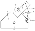
- FIG. 2 shows a connection state between the additional duct 2 and the inside / outside air case 1.
- the inside / outside air case 1 is provided with a shaft hole 11 into which the shaft of the damper 5 is inserted.
- the boundary between the inside / outside air case 1 and the additional duct 2 serves as the outside air introduction port 7 of the inside / outside air case 1.
- An outside air inlet 12 of the additional duct 2 is formed at the tip of the additional duct 2.
- the inside / outside air case 1 and the additional duct 2 are molded using the same synthetic resin, for example, polypropylene.
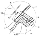
- FIG. 3 shows an enlarged view of the portion indicated by Y3 in FIG.
- the additional duct 2 and the inside / outside air case 1 are coupled by fitting.
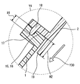
- FIG. 4 shows a part enlarged by Y4 in FIG. 2 and shows a fitting portion between the inside / outside air case 1 and the additional duct 2.
- FIG. 5 shows a partially enlarged portion along the line Y5-Y5 in FIG.
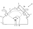
- FIG. 6 a state in which the inside / outside air case 1 and the vehicle side outside air inlet 3 of FIG. 1 are directly connected without providing the additional duct 2 will be described.
- a rubber seal packing 13p is provided at a connection portion between the vehicle-side outside air suction port 3 and the outside air introduction port 7 of the inside / outside air case 1.
- a seal surface portion 16 to be described later is formed at a portion where the additional duct 2 of the inside / outside air case 1 is connected.
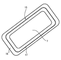
- FIG. 7 schematically shows the shape of the opening end face 15 of the outside air inlet 7 of the inside / outside air case 1 as seen from the direction indicated by the arrow Y7 in FIG.
- the inside / outside air case 1 and the additional duct 2 are connected as shown in FIG. 2, and in another case, the vehicle side outside air inlet 3 is directly connected to the inside / outside air as shown in FIG. It is attached to case 1.
- a part of the opening end face 15 forms a seal face portion 16 in close contact with the seal packing 13p.
- FIG. 7 will be described in which the opening end face 15 and the vehicle-side outside air suction port 3 are directly connected without using the additional duct 2.
- the air exiting the blower casing 8 flows into an air conditioning duct 20 provided with a heat exchanger (not shown) that adjusts the temperature of the conditioned air.
- a blower 9 for sending conditioned air to the air conditioning duct 20 is provided upstream of the air conditioning duct 20.
- the blower 9 is provided in a spiral blower casing 8.
- the blower 9 has a centrifugal fan that is rotated by a blower motor (not shown), and draws air from the center of the centrifugal fan into the inside / outside air case 1 as indicated by an arrow Y3.
- the inside / outside air case 1 has a damper 5 for selectively sending outside air outside the vehicle and inside air inside the vehicle into the blower casing 8.
- the air flow indicated by the arrow Y2 from the inside air inlet 6 selected by the damper 5 or the air flow of the outside air indicated by the arrow Y1 is caused by the rotation of the blower 9.
- the additional duct 2 is not provided between the vehicle side outside air suction port 3 provided on the vehicle side and the inside / outside air case 1, as shown in FIG.
- the inside / outside air case 1 can also be directly connected to the vehicle side outside air inlet 3.
- the configuration shown in FIG. 1 or the configuration shown in FIG. 6 depends on the type of vehicle on which the inside / outside air case 1 is provided. That is, according to the mounting dimension of the vehicle, the additional duct 2 can be provided as shown in FIG. 1 or the additional duct 2 can be omitted.
- the inside / outside air case 1 having a standard (specification) common to many vehicles can be used.
- the seal surface portion 16 is formed at a portion connecting the inside / outside air case 1 to the additional duct 2, and connects the inside / outside air case 1 and the additional duct 2. Further, the seal surface portion 16 is configured to be connectable to the vehicle-side outside air suction port 3.
- the seal surface portion 16 has a flat portion to which a seal packing (13p in FIG. 6) can be attached.
- the seal surface portion 16 is connected to the end of the additional duct 2 as shown in FIGS.
- the seal surface portion 16 is connected to the vehicle-side outside air suction port 3 via a seal packing 13p as shown in FIG.
- a concave portion 17 is formed in the seal surface portion 16 in an annular shape.
- the concave portion 17 is fitted with a convex portion 18 provided at an end portion of the additional duct 2.
- the convex portion 18 is formed in an annular shape at the end of the additional duct 2, and the fitting portions 17 and 18 are formed by fitting the convex portion 18 and the concave portion 17 as shown in FIGS. 3 to 5.
- an annular wall 19 is formed at the end of the additional duct 2.
- the wall portion 19 enters deeply into the inside / outside air case 1 on the inner peripheral side of the opening end face 15.
- the flat portion provided on the seal surface portion 16 (hereinafter, the flat portion is used with the same reference numeral 16 as the seal surface portion) is formed in an annular shape.
- a seal packing 13p is provided on the flat portion 16.
- the flat portion 16 is provided with a circular recess 17.
- an outside air introduction port 7 through which outside air is introduced is formed on the inner peripheral side of the flat portion 16. That is, the recess 17 is provided so as to surround the outside air introduction port 7.
- the convex portion 18 provided in the additional duct 2 surrounds the outside air introduction port 7 of the inside / outside air case 1 in an annular shape.
- the convex portion 18 is referred to as an annular convex portion 18.
- the annular wall portion 19 provided at the end of the additional duct 2 is provided on the inner peripheral side of the annular convex portion 18.
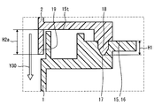
- the height H2 from the opening end surface 15 to the tip of the annular wall 19 is set higher than the height H1 from the opening end surface 15 to the tip of the convex portion 18.
- the height H2 from the opening end surface 15 to the tip of the annular wall 19 is set higher than the height H1 from the opening end surface 15 to the tip of the convex portion 18.
- the height H2a from the opening end face 15t on the additional duct 2 side to the tip of the annular wall 19 is set higher than the height H1 from the opening end face 15 to the tip of the convex part 18. ing.
- the height H ⁇ b> 1 of the convex portion 18 is defined from the opening end surface 15 on the inside / outside air case 1 side having the seal surface portion 16 where the additional duct 2 and the inside / outside air case 1 approach to the tip of the convex portion 18.
- the height H2a of the annular wall portion 19 is the height from the opening end surface 15t on the inside / outside air case 1 side of the additional duct 2 where the additional duct 2 and the inside / outside air case 1 approach each other to the tip of the annular wall portion 19. That's it.
- H1 and H2 (H2a) does not necessarily have to be greater than H1.
- H2 (H2a) water entering from the additional duct 2 side hardly leaks to the outside.
- the air-conditioning duct 20 provided with the heat exchanger which adjusts the temperature of an air-conditioning wind is provided.
- a blower casing 8 is provided on the upstream side of the air conditioning duct 20. Inside the blower casing 8, a blower 9 for sending conditioned air to the air conditioning duct 20 is provided.
- the blower casing 8 is provided with an inside / outside air case 1 having a damper 5 that selects and sends either outside air that is air outside the vehicle or inside air that is air circulating inside the vehicle.
- an additional duct 2 is provided between the vehicle side outside air suction port 3 provided on the vehicle side and sucking outside air and the inside / outside air case 1.
- the seal face 16 is provided on the opening end face 15 connecting the additional duct 2 of the inside / outside air case 1.
- the seal surface portion 16 includes a part of an opening end surface 15 connected to the vehicle-side outside air suction port 3 via a seal packing 13p.
- the seal surface portion 16 is fitted with a convex portion 18 provided at an end portion of the additional duct 2, and has a concave portion 17 that forms a fitting portion together with the convex portion 18. .
- the seal surface portion 16 provided on the opening end surface 15 of the inside / outside air case 1 serves as a connection surface that connects the additional duct 2 and a connection surface that connects the vehicle-side outside air suction port 3 via the seal packing 13p. Function. Therefore, the vehicle-side outside air suction port 3 can be provided in the inside / outside air case 1 via the additional duct 2, or the vehicle-side outside air suction port 3 can be directly connected to the inside / outside air case 1 via the seal packing 13p. . Therefore, when connecting the vehicle side outside air inlet 3 and the inside / outside air case 1, the additional duct 2 can be used or not used. Therefore, the inside and outside of the same standard (specification) can be used between vehicles having different dimensions. Qi case 1 can be used.
- the vehicle-side outside air suction port 3 When the vehicle-side outside air suction port 3 is directly connected to the inside / outside air case 1, it can be easily connected only by providing the seal packing 13 p on the seal surface portion 16.
- the additional duct 2 when the additional duct 2 is used, the inside / outside air case 1 and the additional duct 2 can be easily connected by fitting the convex portion 18 of the additional duct 2 into the concave portion 17 of the seal surface portion 16.
- the end of the additional duct 2 has an annular wall portion 19 that enters the inside of the inside / outside air case 1 rather than the seal surface portion 16.
- the seal surface part 16 has an annular flat part 16 for disposing the seal packing 13p (FIG. 6).
- the flat portion 16 has an outside air introduction port 7 through which outside air is introduced on the inner peripheral side of the flat portion 16, and a concave portion 17 is formed in the flat portion 16.
- the annular seal packing 13p is disposed on the flat portion 16 so that the vehicle-side outside air suction port 3 can be directly coupled to the inside / outside air case 1. Further, the periphery of the outside air introduction port 7 can be sealed with the sealing packing 13p provided on the flat portion 16.
- the convex portion 18 includes an annular convex portion 18 that annularly surrounds the outside air introduction port 7 of the inside / outside air case 1, and the annular wall portion 19 is provided on the inner peripheral side of the annular convex portion 18.
- the connection portion between the inside / outside air case 1 and the additional case 2 is doubly surrounded by the annular wall portion 19 on the inner peripheral side and the annular convex portion 18 on the outer peripheral side. ing. Therefore, even if water enters the inside of the additional duct 2 together with the outside air, it is possible to more reliably suppress water from leaking to the outside of the additional duct 2 or the inside / outside air case 1.
- the convex portion 18 and the annular wall portion 19 are arranged in parallel. 3 to 5, the height H2 from the opening end face 15 (15t) to the tip of the annular wall 19 is higher than the height H1 from the opening end face 15 to the tip of the convex part 18. (H2a) is higher.
- an annular shape from the opening end face 15 is higher than a height H ⁇ b> 1 from the opening end face 15 serving as an end face facing the additional duct 2 and the inside / outside air case 1 to the tip of the convex part 18.
- the height H2 up to the tip of the wall portion 19 is set higher.
- the height from the opening end face 15 that is the opposing end face of the additional duct 2 and the inside / outside air case 1 to the tip of the convex portion 18 is H1.
- the height H2a from the opening end surface 15t on the side of the additional duct 2 that is the opposite end surface of the additional duct 2 and the inside / outside air case 1 to the tip of the annular wall portion 19 is set higher than the height H1. .
- the annular wall portion 19 when connecting the inside / outside air case 1 and the additional duct 2, the annular wall portion 19 is first inserted into the inside / outside air case 1, and then the concave portion 17 of the opening end face 15 and the additional duct 2 are inserted. It is possible to fit the convex portion 18 provided at the end portion of this, and the assembly becomes easy. Further, since the height of the annular wall portion 19 is relatively high, it is possible to more reliably suppress water from leaking to the outside of the additional duct 2 or the inside / outside air case 1.
- the seal packing 23p (FIG. 1) between the vehicle-side outside air suction port 3 and the additional duct 2 and the seal packing 13p (FIG. 6) between the vehicle-side outside air suction port 3 and the inside / outside air case 1 are used as the vehicle-side outside air suction. It may be formed integrally with the mouth 3 or a separate packing may be attached.
- the entire surface of the seal surface portion 16 is the flat portion 16, but a part of the seal surface portion 16 may be a flat portion. That is, a non-flat portion may exist in the seal surface portion 16. That is, it is only necessary that a seal is formed using the seal packing 13p and the additional duct 2 and the inside / outside air case 1 can be connected.
- inside / outside air case 1 and the additional duct 2 are connected by fitting the concave portion 17 and the convex portion 18, but the inside / outside air case 1 and the additional duct are connected using a fastener such as a tapping screw (not shown). 2 may be connected.
Landscapes
- Physics & Mathematics (AREA)
- Thermal Sciences (AREA)
- Engineering & Computer Science (AREA)
- Mechanical Engineering (AREA)
- Air-Conditioning For Vehicles (AREA)
Abstract
車両用空調装置は、ブロワケーシング(8)に車両外部の空気である外気と車両内部を循環する空気である内気とのいずれかを選択して送り込む内外気ケース(1)を有する。また、車両側外気吸込口(3)と内外気ケース(1)との間に設けられた追加ダクト(2)を有する。内外気ケース(1)の追加ダクト(2)を接続する開口部端面(15)は、シール面部(16)を有する。シール面部(16)は、追加ダクト(2)の端部に設けられた凸部(18)と嵌合される凹部(17)を有する。これにより、車両に対し追加ダクト無しで内外気ケースを車両側外気吸込口に接続し、他の車両に対しては、追加ダクトを介して、車両側外気吸込口と内外気ケースとを接続できる。
Description
本出願は、当該開示内容が参照によって本出願に組み込まれた、2013年5月8日に出願された日本特許出願2013-98726を基にしている。
本開示は、車両の室内を空調する車両用空調装置に関するものである。特に、内気と外気とから選択的に空気を吸い込んで空調ダクトに空気を送り込む車両用空調装置の内外気切替装置に関するものである。
従来、特許文献1に記載の車両用内外気切替装置が知られている。車両用空調装置は、内部に蒸発器や凝縮器といった熱交換器を有する空調ダクトを備えている。この空調ダクトの上流側には、内外気切替装置が設けられている。
この内外気切替装置は、車両用空調装置の空調ダクトに空調風を送り込むブロワがブロワケーシング内に収納されている。ブロワケーシングの上端にダンパを収納する内外気ケースが設けられている。内外気ケースの一方には内気を導入する内気導入口が設けられ、他方には外気を導入する外気導入口が設けられている。
この外気導入口は、車両側に設けられ、外気を吸い込む車両側外気吸込口に接続される。そして、外気導入口と車両側外気吸込口との接続面には、シール用パッキンをはさみ込み、接続部のシールが成されている。ここで、一つの内外気ケースを異なる車両間において共用する場合、内外気ケースの外気導入口と車両側外気吸込口とを接続する必要がある。しかしながら、一つの車両に合わせて、内外気ケースの大きさを設定すると、他の車両には適合しないという恐れがある。
そこで、追加ダクトを設け、かつ、車両毎に夫々長さの異なる追加ダクトを設定し、内外気ケースと車両側外気吸込口との間を追加ダクトで接続することが考えられる。しかし、この追加ダクトは、追加ダクトと車両側外気吸込口との間に、シール用パッキンを設けて気密および防水構造を採用しなければならない。しかも、追加ダクトと内外気ケースとの間にもシール用パッキンを設けて、気密および防水構造を設定する必要がある。また、内外気ケースと追加ダクトとが結合できる構造が必要と成り、きわめて複雑な構造が要求される。
本開示は、このような点に鑑み、追加ダクト無しで内外気ケースを車両側外気吸込口に接続したり、追加ダクトを介して車両側外気吸込口と内外気ケースとを接続したりできる車両用空調装置を提供することを目的とする。
従来技術として列挙された特許文献の記載内容は、この明細書に記載された技術的要素の説明として、参照によって導入ないし援用することができる。
本開示は上記目的を達成するために、下記の技術的手段を採用する。すなわち、第1の開示では、空調風の温度を調整する熱交換器が設けられた空調ダクトと、前記空調ダクトの上流側に設けられ、前記空調風を前記空調ダクトに送り込むブロワが内部に設けられたブロワケーシングと、車両の外部の空気である外気と、前記車両の内部を循環する空気である内気とのいずれかを選択して前記ブロワケーシングに送り込むダンパを有する内外気ケースと、前記外気を吸い込む車両側外気吸込口と、前記車両側外気吸込口と前記内外気ケースとの間に設けられ、前記内外気ケースに前記外気を送り込む追加ダクトとを有する。そして、前記内外気ケースの前記追加ダクトを接続する開口部端面に設けられ、前記車両側外気吸込口と接続可能に構成されたシール面部と、前記追加ダクトの端部に設けられた凸部と、前記シール面部に設けられ、前記凸部と嵌合することで前記内外気ケースおよび前記追加ダクトを接続する凹部とを有する。
第1の開示によれば、内外気ケースに外気を送り込むために車両側に設けられ外気を吸い込む車両側外気吸込口と内外気ケースとの間に設けられた追加ダクトを備えている。かつ、内外気ケースの追加ダクトを接続する部分に車両側外気吸込口と接続可能なシール面部を有する。従って、車両側外気吸込口と内外気ケースとの間に追加ダクトを設けない場合、シール面部において車両側外気吸込口と内外気ケースとを直接接続することができる。また、車両側外気吸込口と内外気ケースとの間に追加ダクトを設ける場合は、シール面部の凹部に、追加ダクトの端部に設けられた凸部を嵌合する。この嵌合により内外気ケースと追加ダクトとを容易に接続できる。すなわち、車両側外気吸込口と内外気ケースとを接続する場合において、追加ダクトを用いたり、用いなかったりすることができる。そのため、寸法の異なる車両間において、同じ規格(仕様)の内外気ケースを用いることができる。
第2の開示では、追加ダクトの端部は、追加ダクトと内外気ケースとが接続された場合に、シール面部よりも内外気ケースの内部に進入する環状の壁部を有している。
第2の開示によれば、車両側外気吸込口から外気と共に水が浸入しても、この水は、シール面部よりも内外気ケースの内部に進入する環状の壁部を伝わって、内外気ケースの内部に導かれる。よって、追加ダクトと内外気ケースとの間を伝わって水が内外気ケースの外部に導かれることが無い。従って、水が車両内の予期しない部分に浸入することを抑制することができる。
第3の開示では、シール面部は、シール用パッキンを配設するための環状の平坦部を有し、平坦部は、開口部端面の内周側に外気が導入される外気導入口を有し、平坦部に凹部が形成されている。
第3の開示によれば、シール面部は、シール用パッキンを配設するための環状の平坦部を有する。従って、この平坦部に環状のシール用パッキンを配設して、内外気ケースに車両側外気吸込口を確実にシールして直接結合することができる。また、平坦部の内周側に外気が導入され、平坦部に凹部が形成されているから、シール用パッキンを平坦部に配設することができる。
第4の開示では、凸部は、内外気ケースの外気導入口の周りを環状に取囲む環状凸部から成り、環状の壁部は、環状凸部の内周側に設けられている。
第4の開示によれば、追加ダクトの内部に外気と共に水が侵入しても、内周側の環状の壁部と外周側の環状凸部の両方に取囲まれているから、より確実に、水が追加ダクトまたは内外気ケースの外部に漏れないようにすることができる。従って、水が車両内の予期しない部分に浸入することを抑制することができる。
以下に、図面を参照しながら本開示を実施するための複数の形態を説明する。各形態において先行する形態で説明した事項に対応する部分には同一の参照符号を付して重複する説明を省略する場合がある。各形態において構成の一部を説明している場合は、構成の他の部分については先行して説明した他の形態を適用することができる。
各実施形態で具体的に組合せが可能であることを明示している部分同士の組合せばかりではなく、特に組合せに支障が生じなければ、明示していなくても実施形態同士を部分的に組合せることも可能である。
(第1実施形態)
以下、第1実施形態について図1ないし図7を用いて詳細に説明する。図1は、第1実施形態における内外気ケース1と追加ダクト2と車両側外気吸込口3との関係を示している。内外気ケース1の中には、軸部4を中心に左右に回動するダンパ5が設けられている。車両側外気吸込口3は、実際には、エンジンルームと車室内とを隔てる隔壁に設けられた外気を取り込む開口部であるが、図1等では模式的に図示している。
以下、第1実施形態について図1ないし図7を用いて詳細に説明する。図1は、第1実施形態における内外気ケース1と追加ダクト2と車両側外気吸込口3との関係を示している。内外気ケース1の中には、軸部4を中心に左右に回動するダンパ5が設けられている。車両側外気吸込口3は、実際には、エンジンルームと車室内とを隔てる隔壁に設けられた外気を取り込む開口部であるが、図1等では模式的に図示している。
このダンパ5の矢印Y0方向に沿う回動によって、内外気ケース1が内気導入口6から車室内の空気を導入する場合と、外気導入口7から車両外部の空気を導入する場合とを切替えている。そして内外気ケース1に導入された内気または外気は、内外気ケース1に接続されたブロワケーシング8に導かれる。ブロワケーシング8内には遠心ファンからなるブロワ9が設けられている。そして、ブロワ9によって、空調ダクト20に空調風を供給している。
空調ダクト20内には、空調風を冷却または加熱する図示しない熱交換器や、冷却または加熱度合いを調整するエアミックスダンパ等が設けられている。空調ダクト20内を流れた空調風は、図示しない吹出口から車室内に導かれる。
内外気ケース1と追加ダクト2との境界部である内外気ケース1の外気導入口7部分は、外気と共に浸入してきた水が、追加ダクト2と内外気ケース1との接続部から外部に漏れ出さないようにシールする必要がある。つまり、追加ダクト2と内外気ケース1との間を、シールした状態で結合する必要がある。車両側外気吸込口3と追加ダクト2との間には、シール用パッキン23Pが設けられる。矢印Y1は、車両側外気吸込口3を介して追加ダクト2内に導入される外気の流れを示している。矢印Y2は、車室内を循環する空気である内気が、内外気ケース1に導入される内気の流れを示している。
図2は、追加ダクト2と内外気ケース1との結合状態を示している。内外気ケース1には、ダンパ5の軸が挿入される軸穴11が設けられている。内外気ケース1と追加ダクト2の境界部は、内外気ケース1の外気導入口7と成る。追加ダクト2の先端には、追加ダクト2の外気導入口12が形成されている。内外気ケース1と追加ダクト2とは、同じ合成樹脂、例えばポリプロピレンが使用されて成型されている。
図3は、図2のY3にて示す部分を拡大して示している。図3において、追加ダクト2と内外気ケース1とは、嵌合により結合されている。次に、図4は、図2のY4にて示す部分を一部拡大して示し、内外気ケース1と追加ダクト2との嵌合部を示す。更に、図5は、図2の矢印Y5-Y5線に沿う部分を一部拡大して示している。
図6において、追加ダクト2を設けずに、直接的に内外気ケース1と図1の車両側外気吸込口3とを接続した状態を説明する。車両側外気吸込口3に、内外気ケース1の外気導入口7との接続部には、ゴム製のシール用パッキン13pが設けられる。内外気ケース1の追加ダクト2を接続する部分には、後述するシール面部16が形成されている。
図7は、図6の矢印Y7で示す方向から見た内外気ケース1の外気導入口7の開口部端面15の形状を概略的に示している。この開口部端面15にて、図2のように内外気ケース1と追加ダクト2とが接続され、また別の場合においては、図6のように直接的に車両側外気吸込口3が内外気ケース1に取り付けられる。開口部端面15の一部は、シール用パッキン13pが密接するシール面部16を形成している。
図7の開口部端面15と車両側外気吸込口3とが追加ダクト2を用いず直接的に接続される場合を説明する。図1においてブロワケーシング8を出た空気は、空調風の温度を調整する図示しない熱交換器が設けられた空調ダクト20に流れ込む。この空調ダクト20の上流側には空調風を空調ダクト20に送り込むブロワ9が設けられている。ブロワ9は、渦巻き型のブロワケーシング8内に設けられている。
ブロワ9は、図示しないブロワモータによって回転する遠心ファンを有し、遠心ファンの中心から風を矢印Y3のように内外気ケース1内の風を吸い込む。内外気ケース1内には、ブロワケーシング8内に車両外部の外気と車両内部の内気とを選択して送り込むダンパ5を有する。このダンパ5によって選択された内気導入口6からの矢印Y2にて示す空気の流れ、または、矢印Y1にて示す外気の空気の流れが、ブロワ9の回転によって引き起こされる。
内外気ケース1に外気を取り込むために、車両側に設けられた車両側外気吸込口3と内外気ケース1との間に追加ダクト2を設けることなく、図6に示すように、直接的に内外気ケース1を車両側外気吸込口3に直接接続することもできる。
図1に示す構成とするか図6に示す構成とするかは、内外気ケース1を設ける車両の種類によって異なる。すなわち、車両の取り付け寸法に合わせて、図1のように追加ダクト2を設けたり、追加ダクト2を設けなかったりすることができる。
また、追加ダクト2の寸法は、異なる寸法のものを複数用意すれば、多数の車両に共通の規格(仕様)の内外気ケース1を用いることができる。図3および図7のように、前記シール面部16は、内外気ケース1を追加ダクト2に接続する部分に形成され、内外気ケース1と追加ダクト2とを接続する。また、シール面部16は、車両側外気吸込口3に接続可能に構成されている。このシール面部16は、シール用パッキン(図6の13p)を貼ることができる平坦部を有している。
すなわち、追加ダクト2を用いる場合、シール面部16は、図1、図2のように追加ダクト2の端部と接続される。一方、追加ダクト2を用いない場合、シール面部16は、図6のように車両側外気吸込口3に、シール用パッキン13pを介して接続される。
図7に示すように、シール面部16には、凹部17が環状に形成されている。図3から図5に示すように、凹部17は、追加ダクト2の端部に設けられた凸部18と嵌合される。凸部18は、追加ダクト2の端部に環状に形成され、図3から図5に示すように、凸部18と凹部17とが嵌合することで、嵌合部17、18が形成される。
図3から図5に示すように、追加ダクト2の端部には、環状の壁部19が形成されている。追加ダクト2と内外気ケース1とが接続された際に、前記壁部19は、開口部端面15の内周側において、内外気ケース1の内部に深く進入する。
前記シール面部16に設けられた平坦部(以後、平坦部をシール面部と同じ符号16を用いる)は、環状に形成されている。内外気ケース1と車両側外気吸込口3とが直接接続される場合には、シール用パッキン13pが平坦部16に設けられる。この平坦部16には、環状の凹部17が一巡して設けられている。開口部端面15には、外気が導入される外気導入口7が平坦部16よりも内周側に形成されている。すなわち、凹部17は、外気導入口7の周りを取囲むように設けられている。
図3から図5に示すように、追加ダクト2に設けられた凸部18は、内外気ケース1の外気導入口7の周りを環状に取囲んでいる。以下、凸部18を環状凸部18と称する。そして、追加ダクト2の端部に設けられた環状の壁部19は、環状凸部18の内周側に設けられている。そして内外気ケース1と追加ダクト2とが結合された際に、凸部18と環状の壁部19とが略並行となる(図3から図5参照)。
図3に示すように、開口部端面15から凸部18先端までの高さH1よりも、開口部端面15から環状の壁部19の先端までの高さH2の方が、高く設定されている。図4においても、開口部端面15から凸部18先端までの高さH1よりも、開口部端面15から環状の壁部19の先端までの高さH2の方が、高く設定されている。図5においては、開口部端面15から凸部18先端までの高さH1よりも、追加ダクト2側の開口部端面15tから環状の壁部19先端までの高さH2aの方が、高く設定されている。
図5に示すように凸部18の高さH1とは、追加ダクト2と内外気ケース1とが接近するシール面部16を有する内外気ケース1側の開口部端面15から凸部18先端までの長さである。また、環状の壁部19の高さH2aとは、追加ダクト2と内外気ケース1とが接近する追加ダクト2の内外気ケース1側の開口部端面15tから環状の壁部19先端までの高さである。
なお、この高さH1、H2(H2a)の関係は、必ずしもH2(H2a)のほうがH1よりも大きい関係を有している必要はない。しかし、H2(H2a)がH1よりも大きくなる程度に環状の壁部19の長さを設定することで、追加ダクト2側から浸入する水が、外部に漏れ出し難くなる。
(実施形態の作用効果)
次に上記一実施形態の作用効果について説明する。上記実施形態においては、空調風の温度を調整する熱交換器が設けられた空調ダクト20が設けられている。空調ダクト20の上流側にブロワケーシング8が設けられている。このブロワケーシング8の内部に、空調風を空調ダクト20に送り込むブロワ9が設けられている。
次に上記一実施形態の作用効果について説明する。上記実施形態においては、空調風の温度を調整する熱交換器が設けられた空調ダクト20が設けられている。空調ダクト20の上流側にブロワケーシング8が設けられている。このブロワケーシング8の内部に、空調風を空調ダクト20に送り込むブロワ9が設けられている。
ブロワケーシング8に車両外部の空気である外気と、車両内部を循環する空気である内気とのいずれかを選択して送り込むダンパ5を有する内外気ケース1が設けられている。この内外気ケース1に外気を送り込むため、車両側に設けられ外気を吸い込む車両側外気吸込口3と内外気ケース1との間に、追加ダクト2が設けられている。
内外気ケース1の追加ダクト2を接続する開口部端面15にシール面部16を有している。このシール面部16は、図6に示すように、車両側外気吸込口3に、シール用パッキン13pを介して接続される開口部端面15の一部から成る。シール面部16は、図2から図5に示すように、追加ダクト2の端部に設けられた凸部18と嵌合され、凸部18と共に嵌合部を形成する凹部17を有している。
これによれば、内外気ケース1の開口部端面15に設けたシール面部16は、追加ダクト2を接続する接続面およびシール用パッキン13pを介して車両側外気吸込口3を接続する接続面として機能する。従って、車両側外気吸込口3を追加ダクト2を介して内外気ケース1に設けたり、車両側外気吸込口3を内外気ケース1にシール用パッキン13pを介して直接接続したりすることができる。従って、車両側外気吸込口3と内外気ケース1とを接続する場合において、追加ダクト2を用いたり、用いなかったりすることができるため、寸法の異なる車両間において、同じ規格(仕様)の内外気ケース1を用いることができる。
車両側外気吸込口3を内外気ケース1に直接接続する場合には、シール面部16にシール用パッキン13pを設けるだけで容易に接続することができる。一方、追加ダクト2を用いる場合、シール面部16の凹部17に追加ダクト2の凸部18を嵌合することで、内外気ケース1と追加ダクト2とを容易に接続できる。
次に、追加ダクト2の端部は、追加ダクト2と内外気ケース1とが接続された場合に、シール面部16よりも内外気ケース1の内部に進入する環状の壁部19を有している。
これにより、車両側外気吸込口3から外気と共に水が浸入しても、この水は、壁部19を伝わって内外気ケース1の内部に導かれる(図3~図5の矢印Y30参照)。よって、追加ダクト2と内外気ケース1との間を伝わって水が内外気ケース1の外部に導かれるのを抑制し得る。従って、車両内の予期しない部分に水が浸入することを抑制することができる。
次に、図7のように、シール面部16は、シール用パッキン13p(図6)を配設するための環状の平坦部16を有している。平坦部16は、平坦部16の内周側に外気が導入される外気導入口7を有し、平坦部16に凹部17が形成されている。
従って、この平坦部16に環状のシール用パッキン13pを配設して、内外気ケース1に車両側外気吸込口3を直接的に結合することができる。また、平坦部16に設けたシール用パッキン13pで外気導入口7の周囲をシールすることができる。
次に、凸部18は、内外気ケース1の外気導入口7の周りを環状に取囲む環状凸部18から成り、環状の壁部19は、環状凸部18の内周側に設けられている。これによれば、図3に示すように、内周側の環状の壁部19と外周側の環状凸部18とで内外気ケース1と追加ケース2との接続部が2重に取囲まれている。従って、追加ダクト2の内部に外気と共に水が侵入しても、水が追加ダクト2または内外気ケース1の外部に漏れるのをより確実に抑制することができる。
次に、内外気ケース1と追加ダクト2とが嵌合された場合に、凸部18と環状の壁部19とが並行するようになっている。そして、図3~図5に示すように、開口部端面15から凸部18の先端までの高さH1よりも、開口部端面15(15t)から環状の壁部19の先端までの高さH2(H2a)の方が高くされている。
詳細には、図3および図4に示すように、追加ダクト2と内外気ケース1の対向端面となる開口部端面15から凸部18先端までの高さH1よりも、開口部端面15から環状の壁部19の先端までの高さH2の方が、高く設定されている。図5においては、追加ダクト2と内外気ケース1の対向端面となる開口部端面15から凸部18先端までの高さはH1である。この高さH1よりも、追加ダクト2と内外気ケース1の対向端面となる追加ダクト2側の開口部端面15tから環状の壁部19先端までの高さH2aの方が、高く設定されている。
これによれば、内外気ケース1と追加ダクト2とを結合するときに、先に環状の壁部19を内外気ケース1内に挿入してから、開口部端面15の凹部17と追加ダクト2の端部に設けられた凸部18とを嵌合させることができ、組み付けが容易となる。また、環状の壁部19の高さが比較的高いため、追加ダクト2または内外気ケース1の外部に水が漏れるのをより確実に抑制することができる。
(他の実施形態)
上述の実施形態では、本開示の好ましい実施形態について説明したが、本開示は上述した実施形態に何ら制限されることなく、本開示の主旨を逸脱しない範囲において種々変形して実施することが可能である。上記実施形態の構造は、あくまで例示であって、本開示の範囲はこれらの記載の範囲に限定されるものではない。本開示の範囲は、特許請求の範囲の記載によって示され、さらに特許請求の範囲の記載と均等の意味および範囲内での全ての変更を含むものである。
上述の実施形態では、本開示の好ましい実施形態について説明したが、本開示は上述した実施形態に何ら制限されることなく、本開示の主旨を逸脱しない範囲において種々変形して実施することが可能である。上記実施形態の構造は、あくまで例示であって、本開示の範囲はこれらの記載の範囲に限定されるものではない。本開示の範囲は、特許請求の範囲の記載によって示され、さらに特許請求の範囲の記載と均等の意味および範囲内での全ての変更を含むものである。
車両側外気吸込口3と追加ダクト2の間のシール用パッキン23p(図1)および車両側外気吸込口3と内外気ケース1の間のシール用パッキン13p(図6)は、車両側外気吸込口3と一体に形成されていても良いし、別体のパッキンを貼り付けてもよい。
上記実施形態においては、シール面部16の全面が平坦部16と成っていたが、シール面部16の一部を平坦部としても良い。すなわち、シール面部16の中に平坦でない部分が存在していても良い。すなわち、シール用パッキン13pを用いてシールが成され、追加ダクト2と内外気ケース1とが接続できればよい。
また、凹部17および凸部18が嵌合することで、内外気ケース1および追加ダクト2を接続するようにしたが、図示しないタッピングビス等の締結具を用いて、内外気ケース1と追加ダクト2とを接続しても良い。
Claims (5)
- 空調風の温度を調整する熱交換器が設けられた空調ダクト(20)と、
前記空調ダクト(20)の上流側に設けられ、前記空調風を前記空調ダクト(20)に送り込むブロワ(9)が内部に設けられたブロワケーシング(8)と、
車両の外部の空気である外気と、前記車両の内部を循環する空気である内気とのいずれかを選択して前記ブロワケーシング(8)に送り込むダンパ(5)を有する内外気ケース(1)と、
前記外気を吸い込む車両側外気吸込口(3)と、
前記車両側外気吸込口(3)と前記内外気ケース(1)との間に設けられ、前記内外気ケース(1)に前記外気を送り込む追加ダクト(2)と、
前記内外気ケース(1)の前記追加ダクト(2)を接続する開口部端面(15)に設けられ、前記車両側外気吸込口(3)と接続可能に構成されたシール面部(16)と、
前記追加ダクト(2)の端部に設けられた凸部(18)と、
前記シール面部(16)に設けられ、前記凸部(18)と嵌合することで前記内外気ケース(1)および前記追加ダクト(2)を接続する凹部(17)と、
を備えた車両用空調装置。 - 前記追加ダクト(2)の端部は、前記追加ダクト(2)と前記内外気ケース(1)とが接続された場合に、前記シール面部(16)よりも前記内外気ケース(1)の内部に進入する環状の壁部(19)を有している請求項1に記載の車両用空調装置。
- 前記シール面部(16)は、シール用パッキン(13p)を配設するための環状の平坦部(16)を有し、前記開口部端面(15)は、前記平坦部(16)の内周側に前記外気が導入される外気導入口(7)を有し、前記平坦部(16)に前記凹部(17)が形成されている請求項1または2に記載の車両用空調装置。
- 前記凸部(18)は、前記内外気ケース(1)の外気導入口(7)の周りを環状に取囲む環状凸部(18)から成り、前記環状の壁部(19)は、前記環状凸部(18)の内周側に設けられている請求項2に記載の車両用空調装置。
- 前記内外気ケース(1)と前記追加ダクト(2)とが接続された場合に、前記凸部(18)と前記環状の壁部(19)とが並行し、
前記シール面部(16)から前記凸部(18)の先端までの高さ(H1)よりも、前記シール面部(16)から前記環状の壁部(19)の先端までの高さ(H2)の方が高くされている請求項2または4に記載の車両用空調装置。
Priority Applications (1)
| Application Number | Priority Date | Filing Date | Title |
|---|---|---|---|
| US14/787,487 US20160068039A1 (en) | 2013-05-08 | 2014-05-07 | Vehicle air-conditioning device |
Applications Claiming Priority (2)
| Application Number | Priority Date | Filing Date | Title |
|---|---|---|---|
| JP2013-098726 | 2013-05-08 | ||
| JP2013098726A JP6131703B2 (ja) | 2013-05-08 | 2013-05-08 | 車両用空調装置 |
Publications (1)
| Publication Number | Publication Date |
|---|---|
| WO2014181535A1 true WO2014181535A1 (ja) | 2014-11-13 |
Family
ID=51867023
Family Applications (1)
| Application Number | Title | Priority Date | Filing Date |
|---|---|---|---|
| PCT/JP2014/002418 Ceased WO2014181535A1 (ja) | 2013-05-08 | 2014-05-07 | 車両用空調装置 |
Country Status (3)
| Country | Link |
|---|---|
| US (1) | US20160068039A1 (ja) |
| JP (1) | JP6131703B2 (ja) |
| WO (1) | WO2014181535A1 (ja) |
Families Citing this family (2)
| Publication number | Priority date | Publication date | Assignee | Title |
|---|---|---|---|---|
| US9989252B2 (en) | 2013-08-22 | 2018-06-05 | Noritz Corporation | Exhaust adapter, exhaust structure for water heater, and method for installing exhaust adapter |
| US10436442B2 (en) * | 2015-10-28 | 2019-10-08 | Noritz Corporation | Exhaust tube holding member, exhaust structure for combustion apparatus, and method for installing exhaust structure for combustion apparatus |
Citations (6)
| Publication number | Priority date | Publication date | Assignee | Title |
|---|---|---|---|---|
| JPS62173208U (ja) * | 1986-04-25 | 1987-11-04 | ||
| JPH06135220A (ja) * | 1992-10-26 | 1994-05-17 | Nippondenso Co Ltd | 車両用空調装置 |
| JPH08295118A (ja) * | 1995-04-25 | 1996-11-12 | Nippondenso Co Ltd | 車両用空気調和装置 |
| JP2003118352A (ja) * | 2001-10-17 | 2003-04-23 | Denso Corp | 車両用空調装置 |
| JP2011251555A (ja) * | 2010-05-31 | 2011-12-15 | Mitsubishi Heavy Ind Ltd | 車両用空気調和装置 |
| US20130156499A1 (en) * | 2011-12-19 | 2013-06-20 | Behr Gmbh & Co. Kg | Housing particularly for a motor vehicle hvac system |
Family Cites Families (4)
| Publication number | Priority date | Publication date | Assignee | Title |
|---|---|---|---|---|
| JPH08150825A (ja) * | 1994-11-28 | 1996-06-11 | Kasai Kogyo Co Ltd | ブロワーユニットの取付構造 |
| DE19725127B4 (de) * | 1996-06-17 | 2006-07-06 | Denso Corp., Kariya | Klimaanlage für ein Kraftfahrzeug |
| JPH10309924A (ja) * | 1997-05-12 | 1998-11-24 | Zexel Corp | 自動車用空調装置 |
| JP2004082800A (ja) * | 2002-08-23 | 2004-03-18 | Denso Corp | 車両用空調装置の内外気切替装置 |
-
2013
- 2013-05-08 JP JP2013098726A patent/JP6131703B2/ja not_active Expired - Fee Related
-
2014
- 2014-05-07 WO PCT/JP2014/002418 patent/WO2014181535A1/ja not_active Ceased
- 2014-05-07 US US14/787,487 patent/US20160068039A1/en not_active Abandoned
Patent Citations (6)
| Publication number | Priority date | Publication date | Assignee | Title |
|---|---|---|---|---|
| JPS62173208U (ja) * | 1986-04-25 | 1987-11-04 | ||
| JPH06135220A (ja) * | 1992-10-26 | 1994-05-17 | Nippondenso Co Ltd | 車両用空調装置 |
| JPH08295118A (ja) * | 1995-04-25 | 1996-11-12 | Nippondenso Co Ltd | 車両用空気調和装置 |
| JP2003118352A (ja) * | 2001-10-17 | 2003-04-23 | Denso Corp | 車両用空調装置 |
| JP2011251555A (ja) * | 2010-05-31 | 2011-12-15 | Mitsubishi Heavy Ind Ltd | 車両用空気調和装置 |
| US20130156499A1 (en) * | 2011-12-19 | 2013-06-20 | Behr Gmbh & Co. Kg | Housing particularly for a motor vehicle hvac system |
Also Published As
| Publication number | Publication date |
|---|---|
| JP2014218163A (ja) | 2014-11-20 |
| JP6131703B2 (ja) | 2017-05-24 |
| US20160068039A1 (en) | 2016-03-10 |
Similar Documents
| Publication | Publication Date | Title |
|---|---|---|
| CN109196258B (zh) | 流路切换阀 | |
| CN103807916B (zh) | 空调器 | |
| US10792973B2 (en) | Blower device for air-conditioning of vehicle | |
| US7118355B2 (en) | Electric motor driven blower assembly with integral motor cooling duct | |
| JP4488075B2 (ja) | 電動送風機 | |
| US11274670B2 (en) | Blower | |
| KR20140098181A (ko) | 모터가 냉각되는 충격-흡수 팬 모터 장착부 | |
| CN106029410B (zh) | 汽车用空调装置 | |
| WO2015004836A1 (ja) | 送風機 | |
| US11279207B2 (en) | Blower unit, and method of manufacturing blower unit | |
| CN107531126B (zh) | 车辆用空调装置 | |
| US10215188B2 (en) | Blower | |
| WO2014181535A1 (ja) | 車両用空調装置 | |
| CN109476210A (zh) | 车辆用空调单元 | |
| US9616732B2 (en) | Air outlet for ventilating the interior of a motor vehicle | |
| JP2016035349A (ja) | 室内機ユニット及び空気調和機 | |
| WO2019220925A1 (ja) | 車両用空調ユニット | |
| KR101595326B1 (ko) | 차량의 에어컨디셔닝 댐퍼용 액츄에이터 | |
| JP2009156176A (ja) | 冷却装置 | |
| US10059169B2 (en) | Assembly for collecting and removing leaked refrigerant | |
| US20160039268A1 (en) | Hvac auxiliary duct attachment | |
| JP2010151412A (ja) | 室外ユニットの開口カバー | |
| KR200443748Y1 (ko) | 자동차용 공조장치의 덕트연결구조 | |
| JP2014218163A5 (ja) | ||
| JP6718337B2 (ja) | 車両用空調装置 |
Legal Events
| Date | Code | Title | Description |
|---|---|---|---|
| 121 | Ep: the epo has been informed by wipo that ep was designated in this application |
Ref document number: 14794713 Country of ref document: EP Kind code of ref document: A1 |
|
| WWE | Wipo information: entry into national phase |
Ref document number: 14787487 Country of ref document: US |
|
| NENP | Non-entry into the national phase |
Ref country code: DE |
|
| 122 | Ep: pct application non-entry in european phase |
Ref document number: 14794713 Country of ref document: EP Kind code of ref document: A1 |