WO2014181579A1 - 空気入りタイヤ - Google Patents
空気入りタイヤ Download PDFInfo
- Publication number
- WO2014181579A1 WO2014181579A1 PCT/JP2014/056342 JP2014056342W WO2014181579A1 WO 2014181579 A1 WO2014181579 A1 WO 2014181579A1 JP 2014056342 W JP2014056342 W JP 2014056342W WO 2014181579 A1 WO2014181579 A1 WO 2014181579A1
- Authority
- WO
- WIPO (PCT)
- Prior art keywords
- bead
- core
- tire
- cord
- inner core
- Prior art date
- Legal status (The legal status is an assumption and is not a legal conclusion. Google has not performed a legal analysis and makes no representation as to the accuracy of the status listed.)
- Ceased
Links
Images


Classifications
-
- B—PERFORMING OPERATIONS; TRANSPORTING
- B60—VEHICLES IN GENERAL
- B60C—VEHICLE TYRES; TYRE INFLATION; TYRE CHANGING; CONNECTING VALVES TO INFLATABLE ELASTIC BODIES IN GENERAL; DEVICES OR ARRANGEMENTS RELATED TO TYRES
- B60C15/00—Tyre beads, e.g. ply turn-up or overlap
- B60C15/0009—Tyre beads, e.g. ply turn-up or overlap features of the carcass terminal portion
- B60C15/0018—Tyre beads, e.g. ply turn-up or overlap features of the carcass terminal portion not folded around the bead core, e.g. floating or down ply
-
- B—PERFORMING OPERATIONS; TRANSPORTING
- B60—VEHICLES IN GENERAL
- B60C—VEHICLE TYRES; TYRE INFLATION; TYRE CHANGING; CONNECTING VALVES TO INFLATABLE ELASTIC BODIES IN GENERAL; DEVICES OR ARRANGEMENTS RELATED TO TYRES
- B60C15/00—Tyre beads, e.g. ply turn-up or overlap
- B60C15/04—Bead cores
- B60C15/05—Bead cores multiple, i.e. with two or more cores in each bead
-
- B—PERFORMING OPERATIONS; TRANSPORTING
- B60—VEHICLES IN GENERAL
- B60C—VEHICLE TYRES; TYRE INFLATION; TYRE CHANGING; CONNECTING VALVES TO INFLATABLE ELASTIC BODIES IN GENERAL; DEVICES OR ARRANGEMENTS RELATED TO TYRES
- B60C9/00—Reinforcements or ply arrangement of pneumatic tyres
- B60C9/02—Carcasses
-
- B—PERFORMING OPERATIONS; TRANSPORTING
- B29—WORKING OF PLASTICS; WORKING OF SUBSTANCES IN A PLASTIC STATE IN GENERAL
- B29D—PRODUCING PARTICULAR ARTICLES FROM PLASTICS OR FROM SUBSTANCES IN A PLASTIC STATE
- B29D30/00—Producing pneumatic or solid tyres or parts thereof
- B29D30/06—Pneumatic tyres or parts thereof (e.g. produced by casting, moulding, compression moulding, injection moulding, centrifugal casting)
- B29D30/48—Bead-rings or bead-cores; Treatment thereof prior to building the tyre
-
- B—PERFORMING OPERATIONS; TRANSPORTING
- B60—VEHICLES IN GENERAL
- B60C—VEHICLE TYRES; TYRE INFLATION; TYRE CHANGING; CONNECTING VALVES TO INFLATABLE ELASTIC BODIES IN GENERAL; DEVICES OR ARRANGEMENTS RELATED TO TYRES
- B60C9/00—Reinforcements or ply arrangement of pneumatic tyres
- B60C2009/0071—Reinforcements or ply arrangement of pneumatic tyres characterised by special physical properties of the reinforcements
-
- B—PERFORMING OPERATIONS; TRANSPORTING
- B60—VEHICLES IN GENERAL
- B60C—VEHICLE TYRES; TYRE INFLATION; TYRE CHANGING; CONNECTING VALVES TO INFLATABLE ELASTIC BODIES IN GENERAL; DEVICES OR ARRANGEMENTS RELATED TO TYRES
- B60C15/00—Tyre beads, e.g. ply turn-up or overlap
- B60C15/04—Bead cores
- B60C2015/042—Bead cores characterised by the material of the core, e.g. alloy
-
- B—PERFORMING OPERATIONS; TRANSPORTING
- B60—VEHICLES IN GENERAL
- B60C—VEHICLE TYRES; TYRE INFLATION; TYRE CHANGING; CONNECTING VALVES TO INFLATABLE ELASTIC BODIES IN GENERAL; DEVICES OR ARRANGEMENTS RELATED TO TYRES
- B60C15/00—Tyre beads, e.g. ply turn-up or overlap
- B60C15/04—Bead cores
- B60C2015/046—Cable cores, i.e. cores made-up of twisted wires
Definitions
- the present invention relates to a pneumatic tire, and more particularly, to a pneumatic tire in which an end portion of a carcass ply is sandwiched between an inner core and an outer core in an axial direction of the tire embedded in a bead portion.
- Patent Document 1 proposes a core molding method for producing a pneumatic tire using a core.
- the core has an outer surface equal to the bore surface of the pneumatic tire.
- an inner liner, a carcass ply, a bead core, sidewall rubber, tread rubber and the like are attached to the outer surface of the core.
- the green tire is vulcanized together with the core in the mold so as not to expand and deform in the mold. After vulcanization, the core is disassembled from the tire and taken out.
- the core molding method can provide a pneumatic tire excellent in dimensional stability because deformation of a green tire during vulcanization is small.
- FIG. 9 shows a partial cross-sectional view of the bead portion b of the pneumatic tire produced by the core molding method.
- the carcass c of the pneumatic tire includes a carcass ply c1 composed of an arrangement of carcass cords.
- a bead core d is disposed in the bead portion b.
- the bead core d includes an inner core di disposed on the inner side in the tire axial direction of the carcass ply c1, and an outer core do disposed on the outer side in the tire axial direction of the carcass ply c1.
- Each of the inner core di and the outer core do is configured by winding a plurality of bead cords spirally along the tire circumferential direction.
- the end of the carcass ply c1 is held between the inner core di and the outer core do.
- a heat shrinkable material may be used as the carcass cord.
- Such carcass cords are shrunk by the heat of vulcanization.
- the carcass cords held between the inner core di and the outer core do are thermally shrunk, the carcass cords may bite into the inner liner f due to the increase in the tension of the carcass cords.
- the inner liner f is damaged along the carcass cords, and exhibits an undesirable durability.
- the present invention has been made in view of the above problems, and has as its main object to provide a pneumatic tire having excellent dimensional stability and durability.
- the present invention is a pneumatic tire comprising a carcass ply comprising a carcass ply extending from a tread portion to sidewall portions on both sides to bead cores on bead portions on both sides.
- the bead core includes an inner core disposed axially inward of the carcass ply in the tire axial direction and an outer core disposed axially outward of the carcass ply.
- the carcass ply is sandwiched between the inner core and the outer core.
- the inner core and the outer core each include a bead cord wound at least one turn along a tire circumferential direction, and the bead cord includes an outermost layer in which a plurality of filaments are twisted together .
- a twisting direction of the outermost layer of the bead cords of the inner core and the outer core causes the carcass ply to move outward between the inner core and the outer core in the tire radial direction. It is easy to do.
- the winding direction of the bead cord of the inner core along the tire circumferential direction is the winding of the bead core of the outer core along the tire circumferential direction
- the twisting direction of the outermost layer of the bead cords of the inner core may be opposite to the twisting direction of the outermost layers of the bead cords of the outer core.
- the winding direction of the bead cord of the inner core along the tire circumferential direction is the winding of the bead core of the outer core along the tire circumferential direction
- the twisting direction of the outermost layer of the bead cord of the inner core may be the same as the twisting direction of the outermost layer of the bead cord of the outer core.
- the carcass cord has a ratio (y / x) of a shrinkage amount y when left at 180 ° C. for 5 minutes in a non-loaded state and a length x of carcass cord before leaving.
- the thermal contraction rate represented by (%) may be 1.5% or more.
- the pneumatic tire of the present invention has an inner core and an outer core in at least one bead portion.
- the twisting direction of the outermost layers of the bead cords of the inner core and the outer core is oriented such that the carcass ply can easily move outward from between the inner core and the outer core in the tire radial direction. Therefore, even when thermal contraction of the carcass cords occurs, the carcass cords can move outward between the inner core and the outer core in the tire radial direction. Such movement suppresses the increase in cord tension of the carcass cord and suppresses the biting of the carcass cord into the inner liner. Therefore, the pneumatic tire of the present invention exhibits good durability.
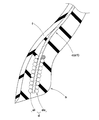
- FIG. 1 is a meridional cross-sectional view of a pneumatic tire according to an embodiment of the present invention. It is an enlarged view of the bead part of FIG. It is a side view of a bead core.
- (A) is a perspective view of Z twist bead cord
- (B) is a perspective view of S twist bead cord.
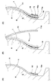
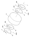
- FIG. 2 is a schematic view of an inner core and an outer core. It is a meridional sectional view of each bead part.
- (A) is an explanatory view of an inner core formation step
- (B) is an explanatory view of a carcass formation step
- (C) is an explanatory view of an outer core formation step.
- FIG. 7 is a schematic view of the inner and outer cores of another embodiment of the present invention. It is sectional drawing of the bead part of the conventional pneumatic tire.
- FIG. 1 shows a meridional cross-sectional view including a tire rotation axis of a pneumatic tire (hereinafter sometimes simply referred to as “tire”) 1 of the present embodiment.
- the tire 1 is provided with a carcass 5 extending from the tread portion 2 through the side wall portions 3 and 3 on both sides to the bead portions 4 and 4 on both sides, and bead cores 4 and 4 arranged in each bead portion 4 And six. Furthermore, the tire 1 of the present embodiment includes a belt layer 7 provided on the tire radial direction outer side of the carcass 5 and an inner liner 8 disposed on the tire radial direction inner side of the carcass 5. Such a tire 1 is used, for example, as a tire for a passenger car.
- the belt layer 7 includes one or more sheets in which belt cords are arranged at an angle of 10 to 40 degrees with respect to the tire equator C, for example, and in the present embodiment, two belt plies 7A and 7B in the tire radial direction. It is.
- the belt plies 7A and 7B are stacked in the direction in which the belt cords cross each other.
- a steel cord and, if necessary, a highly elastic organic fiber cord such as aramid and rayon are used for the belt cord of the present embodiment.
- the inner liner 8 is disposed, for example, across the bead portions 4 and 4 substantially in the entire area of the tire inner cavity surface 9 across the toroidal shape.
- the inner liner 8 is desirably excellent in air impermeability in order to maintain the internal pressure of the tire 1.
- the inner liner 8 is formed of butyl-based rubber containing 50 parts by mass or more of halogenated butyl in the rubber.
- FIG. 2 shows an enlarged view of the bead portion 4 of FIG.
- the carcass 5 is formed of, for example, one or more, in the present embodiment, one carcass ply 11 in which carcass cords of organic fibers are arranged at an angle of 70 to 90 ° with respect to the tire circumferential direction, for example.
- the carcass ply 11 extends in a toroidal shape across the bead portions 4.
- the tire radial direction inner end 11 e of the carcass ply 11 terminates in the bead core 6 without being folded back around the bead core 6.
- the bead core 6 includes an inner core 14 disposed along the tire axial inner surface 5 i of the carcass ply 11 and an outer core 15 disposed along the tire axial outer surface 5 o.
- the inner core 14 and the outer core 15 can hold the end 11 e of the carcass ply 11 from both sides, and can prevent the carcass 5 from being pulled out.
- apex rubbers 20i and 20o made of hard rubber are disposed, and the bead portion 4 is reinforced.
- chafer rubber 21 is disposed which suppresses defects such as damage due to friction with the rim and rim deviation.
- the bead cores 6 include a bead cord 16 wound at least one turn along the tire circumferential direction.
- the inner core 14 and the outer core 15 are formed by spirally winding the bead cord 16 from the inner side to the outer side in the tire radial direction around the tire axis J.
- the bead cord 16 is wound from the inner side to the outer side in the tire radial direction, whereby the inner end 16a in the tire radial direction is fixed.
- each of the inner core 14 and the outer core 15 in the present embodiment is formed in a row in the tire axial direction.
- the inner core 14 and / or the outer core 15 may be formed, for example, in two rows in the tire axial direction in order to increase the bead stiffness.
- the bead cord 16 includes the outermost layer 18 in which a plurality of filaments 17 are twisted.
- the bead cord 16 of the present embodiment has a twist structure including a core 19 including at least one filament 17 and the outermost layer 18 disposed outside thereof.
- the core 19 of the present embodiment is configured by twisting three filaments 17.
- the outermost layer 18 in the present embodiment is configured by twisting eight filaments 17.
- Each filament 17 is desirably made of, for example, steel in order to obtain high strength.
- the bead cord 16 is, for example, a bundle twist (1 ⁇ n) in which n filaments 17 are bundled and twisted, the core 19 and the outermost layer 18
- Various twisting structures may be adopted such as slush twisting in which the twisting direction and twisting pitch are the same, and double twist (m ⁇ n) in which m strands of the n filaments 17 are first twisted.
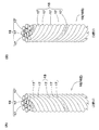
- FIG. 4A shows a Z-twisted bead cord 16Z in which the outermost layer 18 is Z-twisted.
- the “Z twist” is a twist direction in which the direction of the oblique line from the upper right to the lower left of the letter “Z” matches the direction of the spiral appearing in the outermost layer 18 in a plan view of the bead cord 16.
- FIG. 4 (B) shows an S-twisted bead cord 16S in which the outermost layer 18 is S-twisted.
- “S twist” is a twist direction in which the direction of the oblique line from the upper left to the lower right of the letter “S” matches the direction of the spiral appearing in the outermost layer 18 in a plan view of the bead cord 16.
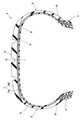
- the inner core 14 and the outer core 15 which are incorporated into the pneumatic tire 1 are conceptually shown in FIG.
- the code G indicates a core.
- the carcass ply 11 of the outermost layer 18 of the bead cord 16 of the inner core 14 and the outer core 15 has an inner core 14 and an outer side. It is set to be easy to move to the outer side in the tire radial direction from between the core 15. That is, since the bead cords 16 of the outermost layers of the inner core 14 and the outer core 15 are configured to be easily deformed by the twisting back Y, the carcass ply 11 is easily moved to the outer side in the tire radial direction.
- the carcass ply 11 can move outward between the inner core 14 and the outer core 15 in the tire radial direction. Therefore, an excessive increase in cord tension of the carcass cord 10 is prevented. This suppresses biting of the carcass cords 10 into the inner liner 8 and improves the durability of the tire 1.
- the inner core 14 and the outer core 15 are configured symmetrically to each other. Therefore, the inner core 14 and the outer core 15 can hold the carcass ply 11 evenly, and the holding performance of the carcass ply 11 is excellent.
- the inner core 14 and the outer core 15 have the same winding direction along the tire circumferential direction of the bead cord 16.
- the twisting direction of the outermost layer 18 of the bead cord 16 of the inner core 14 is opposite to the twisting direction of the outermost layer 18 of the bead cord 16 of the outer core 15.
- the core G is rotated clockwise of the tire axial center J when viewed from the one bead portion 4a side (the front side of FIG. 5).
- the bead cords 16 of the inner core 14 and the outer core 15 spirally wound there are wound counterclockwise in the tire circumferential direction.
- the inner core 14 in one bead portion 4a, is formed of S-twist bead cords 16S, and the outer core 15 is formed of Z-twist bead cords 16Z.
- the inner core 14 is formed of Z-twist bead cords 16Z, and the outer core 15 is formed of S-twist bead cords 16S.
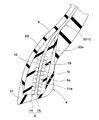
- FIG. 6 shows a meridional cross-sectional view of each bead portion 4a, 4b.
- the heat shrinkage of the carcass cord 10 is preferably 1.5% or more, more preferably 2.0% or more.
- a carcass cord 10 is formed of relatively inexpensive, for example, PET, nylon or the like, and contributes to cost productivity.
- the “heat shrinkage rate” means the ratio (y / x) between the shrinkage amount y when left at 180 ° C. for 5 minutes and the length x before leaving in the unloaded state of the carcass cord 10 It is defined by (%).
- the core G may be rotated counterclockwise of the tire axis J.
- the bead cords 16 of the cores 14 and 15 attached thereto and spirally wound are wound clockwise in the tire circumferential direction.
- bead cords 16 having a twist opposite to that shown in FIG. 5 are used for each of the cores 14 and 15 of each bead portion 4.
- the inner core 14 and the outer core 15 are easy to form the green tire 1 because the bead cords 16 are spirally wound in the same direction.
- the pneumatic tire 1 comprises a green tire forming step of forming a green tire t by sequentially attaching an unvulcanized tire constituent member on the tire forming surface g of the core G; And a vulcanizing step of vulcanizing and molding by charging into a vulcanizing mold.
- the green tire forming process includes an inner core forming process S1, a carcass forming process S2, and an outer core forming process S3.
- the inner core 14 is formed on the tire forming surface g of the core G.
- the inner core 14 is formed by spirally rolling an unvulcanized rubber-coated rubberized bead cord 16 around the tire axial center J from the radially inner side to the outer side. At this time, the tire radial direction inner end 16 a of the bead cord 16 is fixed by the bead cord 16 wound on the outer side in the tire radial direction.
- the radially inner end 11e of the carcass ply 11 is rolled down inward in the tire radial direction, and is affixed to the axially outer side of the inner core 14.
- the outer core 15 is formed on the axially outer side of the inner end 11e of the carcass ply 11 in the tire axial direction.
- the outer core 15 is formed by spirally winding a rubberized bead cord 16 around the tire axial center J from the radially inner side to the outer side.
- the tire radial direction inner end 16 a of the bead cord 16 is fixed by the bead cord 16 wound on the outer side in the tire radial direction.
- the S-twisted bead cord 16S is adopted as the inner core 14 in one bead portion 4a (the front side in FIG. 5).
- One end of the S twist bead cord 16S is fixed to the core side. Since the core G is rotated clockwise with respect to the tire axial center J, the S-twisted bead cord is wound counterclockwise in the tire circumferential direction at one bead portion 4a.
- the Z-twisted bead cord 16 Z is adopted for the outer core 15. One end of the Z twist bead cord 16Z is fixed to the core side.
- the Z-twisted bead cord 16Z is also wound counterclockwise in the tire circumferential direction. Further, in the other bead portion 4b (the heel side in FIG. 5), the Z twist bead cord 16Z as the inner core 14 and the S twist bead cord 16S as the outer core 15 are respectively wound counterclockwise.
- an inner core 14 and an outer core 15 of another embodiment of the present invention are shown together with a core G in FIG.
- the inner core 14 and the outer core 15 have the same twisting direction of the outermost layer 18 of the bead cord 16.
- S-twisted bead cords 16S are used for the inner core 14 and the outer core 15, respectively.
- the winding direction of the bead cord 16 of the inner core 14 along the tire circumferential direction is opposite to the winding direction of the bead cord 16 of the outer core 15 along the tire circumferential direction.
- S-twisted bead cords 16S are used for the inner core 14 and the outer core 15 of each bead portion 4a, 4b.
- the inner core 14 in one bead portion 4a (the front side in FIG. 8), the inner core 14 is wound in a counterclockwise spiral shape, and the outer core 15 is wound in a clockwise spiral shape.
- the inner core 14 is wound in a clockwise spiral, and the outer core 15 is wound in a counterclockwise spiral.
- Z-twisted bead cords 16Z may be used for the inner core 14 and the outer core 15 of each bead portion 4a, 4b.
- the inner core 14 and the outer core 15 of each bead portion 4a, 4b are respectively spirally wound in the direction opposite to the direction shown in FIG.
- the inner core 14 and the outer core 15 are formed of bead cords 16 of either S-twist bead cord 16S or Z-twist bead cord 16Z.
- Such inner core 14 and outer core 15 help the productivity of the bead cord 16.
- a pneumatic tire (225 / 40R18) having the internal structure shown in FIG. 1 was manufactured by a core molding method.
- the bead structure of each sample tire is as shown in Table 1.
- Table 1 For each sample tire, the amount of penetration of the carcass cord into the inner liner and the durability performance were tested.
- the structures of the bead core on one side of the tire equator and the bead core on the other side of each tire are as shown in Table 1.
- the bead cords in Table 1 have a twist structure (2/7 ⁇ 0.37), a cord diameter of 1.41 mm, a twist pitch of 50 mm, and are the same except for the twist direction.
- PET is a cord of 1670/2 dtex
- rayon is a 1840/2 dtex
- aramid is a cord of 1100/2 dtex.
Landscapes
- Engineering & Computer Science (AREA)
- Mechanical Engineering (AREA)
- Tires In General (AREA)
Abstract
カーカスコードのインナーライナへの食い込みを抑制でき、タイヤの耐久性能を向上しうる空気入りタイヤを提供する。トレッド部2からサイドウォール部3を経てビード部4のビードコア5に至るカーカスプライ11からなるカーカス6を具え、ビードコア5は、内側コア14と外側コア15とを含む空気入りタイヤ1である。カーカスプライ11は、内側コア14と外側コア15との間で挟まれている。内側コア14及び外側コア15は、それぞれ、タイヤ周方向に沿って少なくとも1周巻回されたビードコード16を含んでいる。ビードコード16は、複数本のフィラメント17が撚り合わされた最外層18を含み、少なくとも一方のビード部において、内側コア14及び外側コア15の各ビードコード16の最外層18の撚り方向は、カーカスプライ11が内側コア14と外側コア15との間からタイヤ半径方向の外側へ移動しやすい向きとされている。
Description
本発明は、空気入りタイヤに関し、詳しくは、カーカスプライの端部が、ビード部に埋設されたタイヤ軸方向の内側コア及び外側コアに挟まれた空気入りタイヤに関する。
下記特許文献1は、中子を用いて空気入りタイヤを製造する中子成形法を提案している。この中子は、空気入りタイヤの内腔面に等しい外面を具えている。生タイヤを成形するために、中子の外面には、インナーライナ、カーカスプライ、ビードコア、サイドウォールゴム及びトレッドゴムなどが貼り付けられる。生タイヤは、金型内で膨張変形しないように、中子と共に金型内で加硫される。加硫の後、中子は、タイヤから分解されて取り出される。中子成形法は、加硫中の生タイヤの変形が小さいので、寸法安定性に優れた空気入りタイヤを提供することができる。
図9には、中子成形法で作られた空気入りタイヤのビード部bの部分断面図が示されている。空気入りタイヤのカーカスcは、カーカスコードの配列体からなるカーカスプライc1を含んでいる。ビード部bにはビードコアdが配置されている。ビードコアdは、カーカスプライc1のタイヤ軸方向の内側に配された内側コアdiと、カーカスプライc1のタイヤ軸方向外側に配された外側コアdoとを含んでいる。各々の内側コアdi及び外側コアdoは、タイヤ周方向に沿って、ビードコードが渦巻き状に複数巻き付けられて構成されている。カーカスプライc1の端部は、内側コアdiと外側コアdoとの間で保持されている。
カーカスコードとして、熱収縮する材料が用いられることがある。このようなカーカスコードは、加硫時の熱によって縮む。内側コアdi及び外側コアdoの間で保持されたカーカスコードが熱収縮した場合、カーカスコードの張力の上昇により、カーカスコードはインナーライナfに食い込むことがある。このようなタイヤは、例えば、インナーライナfに、カーカスコードに沿った傷が生じ、望ましくない耐久性を示す。
本発明は、以上のような問題点に鑑み案出なされたもので、優れた寸法安定性及び耐久性を有する空気入りタイヤを提供することを主たる目的としている。
本発明は、空気入りタイヤであって、トレッド部から両側のサイドウォール部を経て両側のビード部のビードコアに至るカーカスプライからなるカーカスを具えている。前記ビードコアは、前記カーカスプライのタイヤ軸方向内側に配された内側コアと、前記カーカスプライのタイヤ軸方向外側に配された外側コアとを含んでいる。前記カーカスプライは、前記内側コアと外側コアとの間で挟まれている。前記内側コア及び前記外側コアは、それぞれ、タイヤ周方向に沿って少なくとも1周巻回されたビードコードを含んでおり、前記ビードコードは、複数本のフィラメントが撚り合わされた最外層を含んでいる。少なくとも一方の前記ビード部において、前記内側コア及び外側コアの前記各ビードコードの前記最外層の撚り方向は、前記カーカスプライが前記内側コアと前記外側コアとの間からタイヤ半径方向の外側へ移動しやすい向きとされている。
本発明の空気入りタイヤは、前記少なくとも一方のビード部において、前記内側コアの前記ビードコードのタイヤ周方向に沿った巻回方向は、前記外側コアの前記ビードコードのタイヤ周方向に沿った巻回方向と同じであり、前記内側コアの前記ビードコードの前記最外層の撚り方向は、前記外側コアの前記ビードコードの前記最外層の撚り方向と逆向きであっても良い。
本発明の空気入りタイヤは、前記少なくとも一方のビード部において、前記内側コアの前記ビードコードのタイヤ周方向に沿った巻回方向は、前記外側コアの前記ビードコードのタイヤ周方向に沿った巻回方向と逆向きであり、前記内側コアの前記ビードコードの前記最外層の撚り方向は、前記外側コアの前記ビードコードの前記最外層の撚り方向とは同じであっても良い。
本発明の空気入りタイヤにおいて、前記カーカスコードは、無負荷の状態において、180℃で5分間放置したときの縮み量yと、放置前のカーカスコードの長さxとの比(y/x)(%)で表される熱収縮率が1.5%以上であっても良い。
本発明の空気入りタイヤは、少なくとも一方のビード部において、内側コア及び外側コアを有する。内側コア及び外側コアの各ビードコードの最外層の撚り方向は、カーカスプライが内側コアと外側コアとの間からタイヤ半径方向の外側へ移動しやすい向きとされている。従って、カーカスコードの熱収縮が生じた場合でも、カーカスコードは、内側コアと外側コアとの間から、タイヤ半径方向外側に移動することができる。このような移動は、カーカスコードのコード張力の上昇を抑え、カーカスコードのインナーライナへの食い込みを抑制する。従って、本発明の空気入りタイヤは、良好な耐久性を示す。
以下、本発明の実施の一形態が、図面に基づき説明される。
図1には、本実施形態の空気入りタイヤ(以下、単に「タイヤ」と記載される場合がある)1のタイヤ回転軸を含む子午線断面図が示されている。
図1には、本実施形態の空気入りタイヤ(以下、単に「タイヤ」と記載される場合がある)1のタイヤ回転軸を含む子午線断面図が示されている。
図1に示されるように、タイヤ1は、トレッド部2から両側のサイドウォール部3、3を経て両側のビード部4、4に至るカーカス5と、各ビード部4、4に配されたビードコア6とを具えている。さらに、本実施形態のタイヤ1は、カーカス5のタイヤ半径方向外側に設けられたベルト層7と、カーカス5のタイヤ半径方向内側に配されたインナーライナ8とを具えている。このようなタイヤ1は、例えば、乗用車用のタイヤとして用いられる。
ベルト層7は、ベルトコードをタイヤ赤道Cに対して、例えば、10~40度の角度で配列した1枚以上、本実施形態では、タイヤ半径方向の内外2枚のベルトプライ7A、7Bを含んでいる。これらベルトプライ7A、7Bは、ベルトコードが互いに交差する向きに重ねられている。本実施形態のベルトコードには、スチールコードや、必要に応じてアラミド、レーヨン等の高弾性の有機繊維コードが用いられる。
インナーライナ8は、例えば、ビード部4、4間をトロイド状に跨ってタイヤ内腔面9の略全域に配置される。インナーライナ8は、タイヤ1の内圧を保持するために、空気非透過性に優れるのが望ましく、例えば、ゴム中にハロゲン化ブチルを50質量部以上含むブチル系ゴムから形成される。
図2には、図1のビード部4の拡大図が示されている。カーカス5は、例えば、有機繊維のカーカスコードをタイヤ周方向に対して例えば70~90゜の角度で配列した1枚以上、本実施形態では1枚のカーカスプライ11から形成されている。図1又は図2に示されるように、カーカスプライ11は、ビード部4、4間を跨ってトロイド状にのびている。カーカスプライ11のタイヤ半径方向内側の端部11eは、ビードコア6の廻りで折り返されることなくビードコア6内で終端している。
ビードコア6は、カーカスプライ11のタイヤ軸方向の内側面5iに沿って配される内側コア14と、タイヤ軸方向の外側面5oに沿って配される外側コア15とを含んでいる。これらの内側コア14及び外側コア15は、カーカスプライ11の端部11eを両側から保持し、カーカス5の引き抜けを防止しうる。なお、ビード部4には、硬質のゴムからなるエーペックスゴム20i、20oが配され、ビード部4が補強されている。また、ビード部4には、リムとの摩擦による損傷やリムずれ等の不具合を抑制するチェーファーゴム21が配されている。
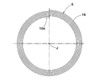
図3には、ビードコア6の側面図が示される。図1乃至図3に示されるように、ビードコア6(各内側コア14及び外側コア15)は、タイヤ周方向に沿って少なくとも1周巻回されたビードコード16を含んでいる。本実施形態では、内側コア14及び外側コア15は、タイヤ軸芯J回りに、ビードコード16をタイヤ半径方向内側から外側に渦巻き状に巻き重ねて形成されている。ビードコード16は、タイヤ半径方向内側から外側に巻き重ねられることにより、そのタイヤ半径方向の内側端部16aが固定される。
図2に示されるように、本実施形態の内側コア14及び外側コア15の各々は、タイヤ軸方向に一列で形成されている。内側コア14及び/又は外側コア15は、ビード剛性を高めるために、例えば、タイヤ軸方向に二列で形成されても良い。
図4(A)及び(B)に示されるように、ビードコード16は、複数本のフィラメント17が撚り合わされた最外層18を含んでいる。本実施形態のビードコード16は、少なくとも1本のフィラメント17を含むコア19と、その外側に配される前記最外層18とを含む撚り構造を有する。
本実施形態のコア19は、3本のフィラメント17を撚り合わせて構成されている。本実施形態の最外層18は、8本のフィラメント17を撚り合わせて構成されている。各フィラメント17は、大きな強度を得るために、例えば、スチールからなるのが望ましい。
ビードコード16は、最外層18のフィラメント17の撚り方向が特定されるならば、例えば、n本のフィラメント17を束ねて撚り合わせた束撚り(1×n)、コア19と最外層18とで撚り方向、撚りピッチを同一としたスラッシュ撚り、n本のフィラメント17を下撚りしたストランドのm本を撚り合わせた複撚り(m×n)など、種々の撚り構造が採用されても良い。
図4(A)には、最外層18がZ撚りであるZ撚りビードコード16Zが示されている。「Z撚り」とは、文字「Z」の右上から左下への斜めの線の向きと、ビードコード16の平面視において最外層18に表れる螺旋の向きとが一致する撚り方向である。図4(B)には、最外層18がS撚りであるS撚りビードコード16Sが示されている。「S撚り」とは、文字「S」の左上から右下への斜めの線の向きと、ビードコード16の平面視において最外層18に表れる螺旋の向きとが一致する撚り方向である。
ビードコード16は、撚りをさらに加える方向の外力が作用すると、その最外層18のフィラメント17は変形し難い。逆に、ビードコード16は、撚りが解れる方向の外力が作用すると、その最外層18のフィラメント17は変形し易い(撚り戻り)。また、ビードコード16のタイヤ半径方向の内側端部16aは、固定されるため、ビードコード16の最外層18のフィラメント17の前記「変形」は、ビードコア6のタイヤ半径方向外側の部分に位置するビードコード16で生じ易い。
図5には、空気入りタイヤ1に組み込まれる内側コア14及び外側コア15が、概念的に示されている。符号Gは、中子を示している。図5に示されるように、本実施形態では、少なくとも一方のビード部4において、内側コア14及び外側コア15のビードコード16の最外層18の撚り方向は、カーカスプライ11が内側コア14と外側コア15との間からタイヤ半径方向の外側へ移動しやすい向きとされている。即ち、内側コア14及び外側コア15の最外層のビードコード16は、撚り戻りYにより、変形しやすく構成されているため、カーカスプライ11がタイヤ半径方向外側に移動しやすい。
例えば、カーカスコード10が熱収縮した場合、カーカスプライ11は、内側コア14と外側コア15との間から、タイヤ半径方向外側に移動することができる。従って、カーカスコード10のコード張力の過大な上昇が防止される。これは、カーカスコード10のインナーライナ8への食い込みを抑制し、タイヤ1の耐久性を向上させる。
好ましくは、内側コア14と外側コア15とは、互いに対称的に構成される。従って、内側コア14及び外側コア15は、カーカスプライ11を均等に挟持でき、カーカスプライ11の保持性能に優れる
本実施形態では、各ビード部4において、内側コア14及び外側コア15は、ビードコード16のタイヤ周方向に沿った巻回方向が等しい。また、各ビード部4において、内側コア14のビードコード16の最外層18の撚り方向は、外側コア15のビードコード16の最外層18の撚り方向と逆向きとされている。
図5の実施形態では、一方のビード部4a側(図5の手前側)から見たときに、中子Gがタイヤ軸心Jの時計回りに回転される。これにより、そこに渦巻き状に巻回される各内側コア14及び外側コア15のビードコード16は、タイヤ周方向に反時計回りに巻回される。この実施形態では、一方のビード部4aにおいて、内側コア14は、S撚りビードコード16Sから形成され、外側コア15は、Z撚りビードコード16Zから形成されている。他方のビード部4b(図5の奧側)において、内側コア14は、Z撚りビードコード16Zから形成され、外側コア15は、S撚りビードコード16Sから形成されている。
図6には、各ビード部4a、4bの子午線断面図が示されている。カーカスプライ11がタイヤ半径方向外側へ移動する場合、各ビード部4a、4bにおいて、内側コア14及び外側コア15のビードコード16の最外層18に撚り戻りYが生じる。このため、カーカスプライ11は、カーカスコード10のコード張力が緩和されるように、矢印Aで示されるようにタイヤ半径方向外側に移動可能である。
カーカスコード10の熱収縮率が小さい場合、カーカスコード10のコード張力が過度に上昇せず、カーカスコード10は、インナーライナ8への食い込み量は小さい。従って、本実施形態は、カーカスコード10の熱収縮率が、好ましくは、1.5%以上、より好ましくは、2.0%以上のものに適用されることで、上記作用・効果がより有効に発揮される。このようなカーカスコード10は、比較的安価な、例えば、PETやナイロン等から形成され、コスト面での生産性に役立つ。
ここで、前記「熱収縮率」とは、カーカスコード10の無負荷の状態において、180℃で5分間放置したときの縮み量yと、放置前の長さxとの比(y/x)(%)で定義される。
図5の実施形態の変形例として、中子Gは、タイヤ軸心Jの反時計回りに回転されても良い。この場合、そこに貼り付けられて渦巻き状に巻回される各コア14、15のビードコード16は、タイヤ周方向に時計回りに巻回される。この場合、各ビード部4の各コア14、15には、それぞれ、図5で示されているものと逆方向の撚りを持ったビードコード16が用いられる。図5及びその変形例の実施形態では、内側コア14及び外側コア15は、ビードコード16が同じ方向に渦巻き状に巻回されているため、生タイヤ1の形成が容易である。
図7(A)~(C)には、上述のような空気入りタイヤ1の製造方法が説明される。
空気入りタイヤ1は、中子Gのタイヤ形成面g上に、未加硫のタイヤ構成部材を順次貼り付けることにより生タイヤtを形成する生タイヤ形成工程と、この生タイヤtを中子Gごと加硫金型内に投入して加硫成形する加硫工程とを含んで製造される。
空気入りタイヤ1は、中子Gのタイヤ形成面g上に、未加硫のタイヤ構成部材を順次貼り付けることにより生タイヤtを形成する生タイヤ形成工程と、この生タイヤtを中子Gごと加硫金型内に投入して加硫成形する加硫工程とを含んで製造される。
生タイヤ形成工程は、内側コア形成工程S1と、カーカス形成工程S2と、外側コア形成工程S3とを含んでいる。
図7(A)に示されるように、内側コア形成工程S1では、中子Gのタイヤ形成面g上で、内側コア14が形成される。内側コア14は、未加硫のゴムで被覆されたゴム引きのビードコード16をタイヤ軸芯J廻りで、半径方向内側から外側に渦巻き状に巻き重ねて形成される。このとき、ビードコード16のタイヤ半径方向内端16aは、タイヤ半径方向外側に巻き重ねられるビードコード16により固定される。
図7(B)に示されるように、カーカス形成工程S2では、カーカスプライ11の半径方向内端11eがタイヤ半径方向内側に巻き下ろされ、内側コア14のタイヤ軸方向外側に貼付けられる。
図7(C)に示されるように、外側コア形成工程S3では、カーカスプライ11の内端11eのタイヤ軸方向外側に、外側コア15が形成される。外側コア15は、ゴム引きのビードコード16をタイヤ軸芯J廻りで、半径方向内側から外側に渦巻き状に巻き重ねて形成される。このとき、ビードコード16のタイヤ半径方向内端16aは、タイヤ半径方向外側に巻き重ねられるビードコード16により固定される。
内側コア形成工程S1及び外側コア形成工程S3において、図5に示した実施形態では、一方のビード部4a(図5の手前側)では、内側コア14としてS撚りビードコード16Sが採用される。S撚りビードコード16Sの一端は、中子側に固定される。中子Gは、タイヤ軸心Jに関して時計回りに回転されるので、一方のビード部4aでは、S撚りビードコードがタイヤ周方向で反時計回りに巻回される。一方のビード部4aでは、外側コア15に、Z撚りビードコード16Zが採用される。Z撚りビードコード16Zの一端は、中子側に固定される。中子がタイヤ軸心Jに関して時計回りに回転されるので、Z撚りビードコード16Zも、タイヤ周方向で反時計回りに巻回される。また、他方のビード部4b(図5の奧側)において、内側コア14としてZ撚りビードコード16Zが、外側コア15としてS撚りビードコード16Sが、それぞれ反時計回りに巻回される。
図8には、本発明の他の実施形態の内側コア14及び外側コア15が、中子Gとともに示されている。図8に示されるように、この実施形態では、各ビード部4a、4bにおいて、内側コア14及び外側コア15は、ビードコード16の最外層18の撚り方向が互いに等しい。本実施形態では、内側コア14及び外側コア15に、それぞれ、S撚りビードコード16Sが用いられている。さらに、内側コア14のビードコード16のタイヤ周方向に沿った巻回方向は、外側コア15のビードコード16のタイヤ周方向に沿った巻回方向と逆向きである。
より具体的には、各ビード部4a、4bの内側コア14及び外側コア15にS撚りビードコード16Sが用いられている。この場合、一方のビード部4a(図8の手前側)では、内側コア14は、反時計回りの渦巻き状に巻回され、外側コア15は、時計回りの渦巻き状に巻回されている。また、他方のビード部4b(図8の奧側)では、内側コア14は、時計回りの渦巻き状に巻回され、外側コア15は、反時計回りの渦巻き状に巻回されている。このような構成により、タイヤ1は、前記実施形態と同様に、撚り戻りYにより、カーカスコード10のインナーライナ8への食い込みを抑制でき、タイヤ1の耐久性を向上しうる。
図8の実施形態の変形例として、各ビード部4a、4bの内側コア14及び外側コア15に、それぞれZ撚りビードコード16Zが用いられても良い。この場合、各ビード部4a、4bの各内側コア14及び外側コア15は、それぞれ、図8で示されている方向と逆向きに渦巻き状に巻回される。
図8及びその変更例の実施形態では、内側コア14及び外側コア15は、S撚りビードコード16S又はZ撚りビードコード16Zのうちいずれか一方の撚りのビードコード16から形成される。このような内側コア14及び外側コア15は、ビードコード16の生産性に役立つ。
以上、本発明の特に好ましい実施形態について詳述したが、本発明はこれらの実施形態に限定されることなく、種々の態様に変形して実施しうる。
本発明の効果を確認するために、図1に示される内部構造を有する空気入りタイヤ(225/40R18)が、中子成形法で製造された。各試供タイヤのビード構造は、表1の示される通りである。各試供タイヤについて、カーカスコードのインナーライナへの食い込み量と耐久性能とがテストされた。各タイヤのタイヤ赤道の一方側のビードコア及び他方側のビードコアの構造は、表1の通りである。
表1中のビードコードは、撚り構造(2/7×0.37)、コード径1.41mm、撚りピッチ50mmであり、撚り方向以外は、同じである。カーカスコードに関し、PETは1670/2dtex、レーヨンは1840/2dtex、アラミドは1100/2dtexのコードである。
<カーカスコードの食い込み量>
各試作タイヤを加硫した後、インナーライナへのカーカスコードの食い込み量が測定された。評価は、食い込み量の逆数について行われ、実施例1を100とする指数で表示されている。数値が大きいほど良好である。
各試作タイヤを加硫した後、インナーライナへのカーカスコードの食い込み量が測定された。評価は、食い込み量の逆数について行われ、実施例1を100とする指数で表示されている。数値が大きいほど良好である。
<耐久性能>
各供試タイヤを8.5Jのリム及び210kPaの内圧の条件下で、ドラム試験機上を速度80km/hで走行させ、タイヤが破壊するまでの走行距離が測定された。評価は、実施例1の走行距離を100とする指数で表示されている。数値が大きいほど良好である。
各供試タイヤを8.5Jのリム及び210kPaの内圧の条件下で、ドラム試験機上を速度80km/hで走行させ、タイヤが破壊するまでの走行距離が測定された。評価は、実施例1の走行距離を100とする指数で表示されている。数値が大きいほど良好である。

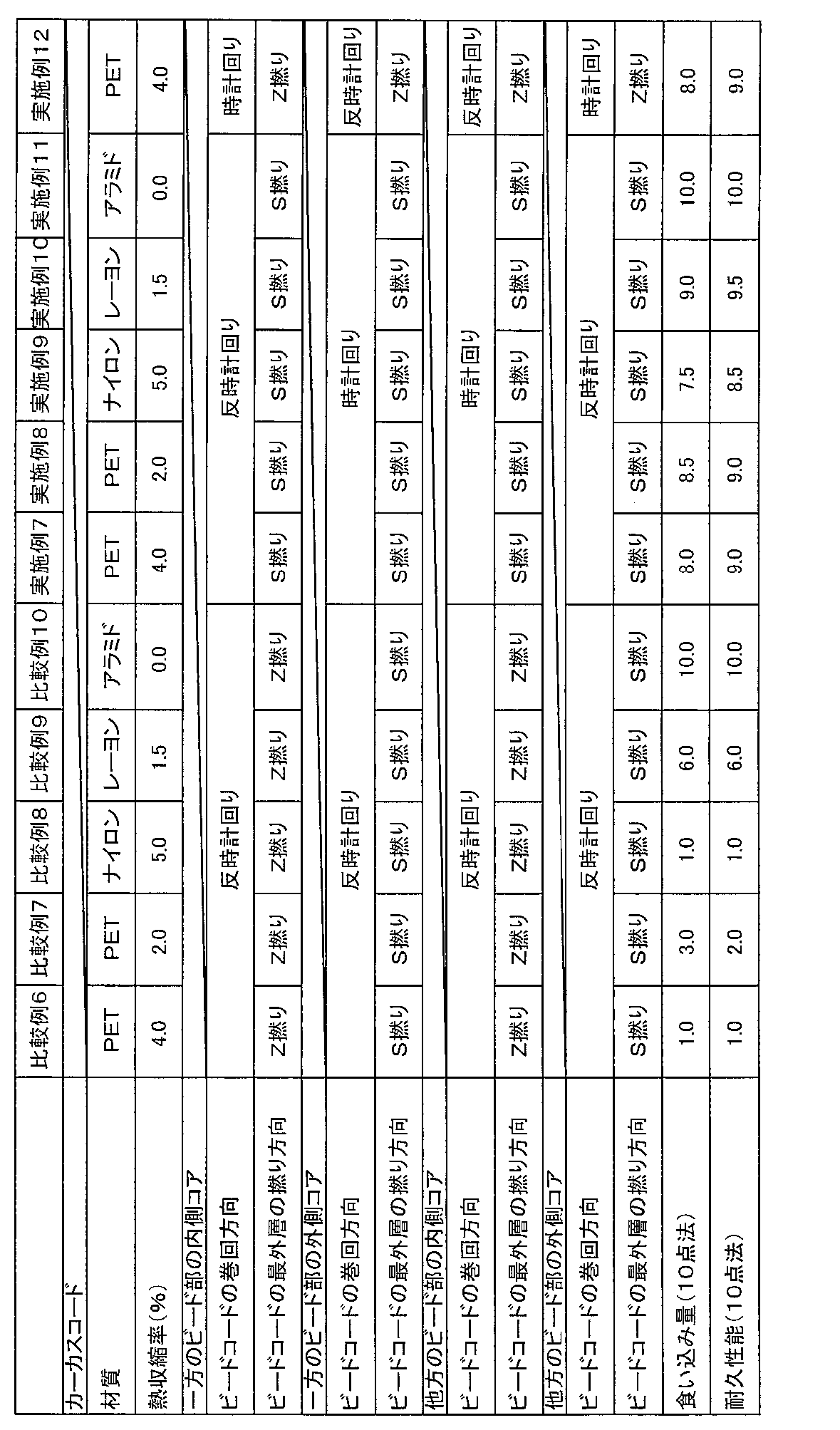
表1に示されるように、実施例のタイヤは、カーカスコードのインナーライナへの食い込みが抑制され、タイヤの耐久性を向上していることが確認できた。
1 空気入りタイヤ
4 ビード部
5 カーカス
6 ビードコア
8 インナーライナ
11 カーカスプライ
14 内側コア
15 外側コア
16 ビードコード
18 最外層
4 ビード部
5 カーカス
6 ビードコア
8 インナーライナ
11 カーカスプライ
14 内側コア
15 外側コア
16 ビードコード
18 最外層
Claims (4)
- 空気入りタイヤであって、
トレッド部から両側のサイドウォール部を経て両側のビード部のビードコアに至るカーカスプライからなるカーカスを具え、
前記ビードコアは、前記カーカスプライのタイヤ軸方向内側に配された内側コアと、前記カーカスプライのタイヤ軸方向外側に配された外側コアとを含み、
前記カーカスプライは、前記内側コアと外側コアとの間で挟まれており、
前記内側コア及び前記外側コアは、それぞれ、タイヤ周方向に沿って少なくとも1周巻回されたビードコードを含み、
前記ビードコードは、複数本のフィラメントが撚り合わされた最外層を含み、
少なくとも一方の前記ビード部において、前記内側コア及び外側コアの前記各ビードコードの前記最外層の撚り方向は、前記カーカスプライが前記内側コアと前記外側コアとの間からタイヤ半径方向の外側へ移動しやすい向きとされていることを特徴とする空気入りタイヤ。 - 前記少なくとも一方のビード部において、前記内側コアの前記ビードコードのタイヤ周方向に沿った巻回方向は、前記外側コアの前記ビードコードのタイヤ周方向に沿った巻回方向と同じであり、
前記内側コアの前記ビードコードの前記最外層の撚り方向は、前記外側コアの前記ビードコードの前記最外層の撚り方向と逆向きである請求項1記載の空気入りタイヤ。 - 前記少なくとも一方のビード部において、前記内側コアの前記ビードコードのタイヤ周方向に沿った巻回方向は、前記外側コアの前記ビードコードのタイヤ周方向に沿った巻回方向と逆向きであり、
前記内側コアの前記ビードコードの前記最外層の撚り方向は、前記外側コアの前記ビードコードの前記最外層の撚り方向とは同じである請求項1記載の空気入りタイヤ。 - 前記カーカスコードは、無負荷の状態において、180℃で5分間放置したときの縮み量yと、放置前のカーカスコードの長さxとの比(y/x)(%)で表される熱収縮率が1.5%以上である請求項1乃至3のいずれかに記載の空気入りタイヤ。
Priority Applications (3)
| Application Number | Priority Date | Filing Date | Title |
|---|---|---|---|
| CN201480023255.8A CN105142936B (zh) | 2013-05-07 | 2014-03-11 | 充气轮胎 |
| EP14794067.0A EP2987657B1 (en) | 2013-05-07 | 2014-03-11 | Pneumatic tire |
| US14/785,250 US10112445B2 (en) | 2013-05-07 | 2014-03-11 | Pneumatic tire |
Applications Claiming Priority (2)
| Application Number | Priority Date | Filing Date | Title |
|---|---|---|---|
| JP2013-097799 | 2013-05-07 | ||
| JP2013097799A JP5973955B2 (ja) | 2013-05-07 | 2013-05-07 | 空気入りタイヤ |
Publications (1)
| Publication Number | Publication Date |
|---|---|
| WO2014181579A1 true WO2014181579A1 (ja) | 2014-11-13 |
Family
ID=51867065
Family Applications (1)
| Application Number | Title | Priority Date | Filing Date |
|---|---|---|---|
| PCT/JP2014/056342 Ceased WO2014181579A1 (ja) | 2013-05-07 | 2014-03-11 | 空気入りタイヤ |
Country Status (5)
| Country | Link |
|---|---|
| US (1) | US10112445B2 (ja) |
| EP (1) | EP2987657B1 (ja) |
| JP (1) | JP5973955B2 (ja) |
| CN (1) | CN105142936B (ja) |
| WO (1) | WO2014181579A1 (ja) |
Families Citing this family (5)
| Publication number | Priority date | Publication date | Assignee | Title |
|---|---|---|---|---|
| KR101775321B1 (ko) * | 2016-03-17 | 2017-09-06 | 한국타이어 주식회사 | 비드부 강성을 강화한 공기압 타이어 |
| JP6848262B2 (ja) * | 2016-08-22 | 2021-03-24 | 住友ゴム工業株式会社 | 空気入りタイヤ |
| JP7245632B2 (ja) * | 2018-10-31 | 2023-03-24 | 株式会社ブリヂストン | タイヤ |
| JP7132172B2 (ja) * | 2019-05-07 | 2022-09-06 | 株式会社ブリヂストン | 空気入りタイヤ |
| JP7010356B1 (ja) * | 2020-12-07 | 2022-02-10 | 横浜ゴム株式会社 | 空気入りタイヤ |
Citations (4)
| Publication number | Priority date | Publication date | Assignee | Title |
|---|---|---|---|---|
| JP2008013135A (ja) * | 2006-07-07 | 2008-01-24 | Yokohama Rubber Co Ltd:The | 空気入りタイヤ |
| JP2008273435A (ja) * | 2007-05-01 | 2008-11-13 | Bridgestone Corp | 空気入りタイヤ |
| JP2012106441A (ja) * | 2010-11-18 | 2012-06-07 | Sumitomo Rubber Ind Ltd | 空気入りタイヤの製造方法 |
| JP2012158064A (ja) | 2011-01-31 | 2012-08-23 | Sumitomo Rubber Ind Ltd | 空気入りタイヤの製造方法 |
Family Cites Families (10)
| Publication number | Priority date | Publication date | Assignee | Title |
|---|---|---|---|---|
| JPS5975804A (ja) * | 1982-10-21 | 1984-04-28 | Bridgestone Corp | 高耐久性ラジアルタイヤ |
| JP3777241B2 (ja) * | 1997-05-06 | 2006-05-24 | 横浜ゴム株式会社 | 空気入りラジアルタイヤ |
| JP2001097010A (ja) * | 1999-09-30 | 2001-04-10 | Bridgestone Corp | 空気入りタイヤ |
| JP2006044339A (ja) * | 2004-08-02 | 2006-02-16 | Yokohama Rubber Co Ltd:The | 空気入りラジアルタイヤ |
| FR2879500A1 (fr) * | 2004-12-22 | 2006-06-23 | Michelin Soc Tech | Procede et dispositif pour la fabrication et la pose d'un renforcement circonferentiel pour pneumatique et pneumatique obtenu par ledit procede |
| JP4312173B2 (ja) * | 2005-05-24 | 2009-08-12 | 住友ゴム工業株式会社 | 自動二輪車用空気入りタイヤ |
| JP2010115957A (ja) * | 2008-11-11 | 2010-05-27 | Bridgestone Corp | 空気入りタイヤのビード部構造 |
| JP5227392B2 (ja) * | 2010-12-16 | 2013-07-03 | 住友ゴム工業株式会社 | 空気入りタイヤ及び空気入りタイヤの製造方法 |
| JP2013082143A (ja) | 2011-10-11 | 2013-05-09 | Sumitomo Rubber Ind Ltd | 空気入りタイヤの製造方法、及びそれによって形成された空気入りタイヤ |
| JP6074230B2 (ja) * | 2012-11-09 | 2017-02-01 | 住友ゴム工業株式会社 | 空気入りタイヤ、及びその製造方法 |
-
2013
- 2013-05-07 JP JP2013097799A patent/JP5973955B2/ja not_active Expired - Fee Related
-
2014
- 2014-03-11 WO PCT/JP2014/056342 patent/WO2014181579A1/ja not_active Ceased
- 2014-03-11 EP EP14794067.0A patent/EP2987657B1/en active Active
- 2014-03-11 CN CN201480023255.8A patent/CN105142936B/zh active Active
- 2014-03-11 US US14/785,250 patent/US10112445B2/en not_active Expired - Fee Related
Patent Citations (4)
| Publication number | Priority date | Publication date | Assignee | Title |
|---|---|---|---|---|
| JP2008013135A (ja) * | 2006-07-07 | 2008-01-24 | Yokohama Rubber Co Ltd:The | 空気入りタイヤ |
| JP2008273435A (ja) * | 2007-05-01 | 2008-11-13 | Bridgestone Corp | 空気入りタイヤ |
| JP2012106441A (ja) * | 2010-11-18 | 2012-06-07 | Sumitomo Rubber Ind Ltd | 空気入りタイヤの製造方法 |
| JP2012158064A (ja) | 2011-01-31 | 2012-08-23 | Sumitomo Rubber Ind Ltd | 空気入りタイヤの製造方法 |
Also Published As
| Publication number | Publication date |
|---|---|
| US20160082784A1 (en) | 2016-03-24 |
| EP2987657A4 (en) | 2016-12-28 |
| CN105142936B (zh) | 2017-03-08 |
| JP5973955B2 (ja) | 2016-08-23 |
| EP2987657A1 (en) | 2016-02-24 |
| JP2014218131A (ja) | 2014-11-20 |
| CN105142936A (zh) | 2015-12-09 |
| US10112445B2 (en) | 2018-10-30 |
| EP2987657B1 (en) | 2018-03-07 |
Similar Documents
| Publication | Publication Date | Title |
|---|---|---|
| US8104525B2 (en) | Pneumatic tire | |
| US20090107605A1 (en) | Pneumatic tire and method for producing same | |
| US20110083782A1 (en) | Pneumatic tire | |
| JP5775592B2 (ja) | 空気入りタイヤの製造方法及び空気入りタイヤ | |
| WO2014181579A1 (ja) | 空気入りタイヤ | |
| CN110023101A (zh) | 充气轮胎 | |
| WO2009091066A1 (ja) | 空気入りラジアルタイヤ | |
| US20170100964A1 (en) | Pneumatic tire, and pneumatic tire production method | |
| CN108274959B (zh) | 充气轮胎及其生产方法 | |
| JP5384255B2 (ja) | 空気入りタイヤ | |
| JP5355067B2 (ja) | 空気入りタイヤおよびその製造方法 | |
| JP6374832B2 (ja) | 空気入りタイヤ | |
| JP3777241B2 (ja) | 空気入りラジアルタイヤ | |
| JP5305389B2 (ja) | 空気入りラジアルタイヤ | |
| JP2015212109A (ja) | 空気入りタイヤ | |
| JP6235859B2 (ja) | 空気入りタイヤの製造方法及びバンドストリップ | |
| JP5294405B2 (ja) | 空気入りラジアルタイヤ | |
| JP2014117978A (ja) | ビードコア、それを用いた空気タイヤ、及び空気入りタイヤの製造方法 | |
| JP2017001673A (ja) | 空気入りタイヤ、及びその製造方法 | |
| JP2014201136A (ja) | 空気入りタイヤ | |
| JP2006044339A (ja) | 空気入りラジアルタイヤ | |
| JP6805755B2 (ja) | 空気入りタイヤ | |
| JPH06297906A (ja) | 空気入りラジアルタイヤ | |
| JP2005041396A (ja) | 空気入りラジアルタイヤ及びその製造方法 | |
| JP2011230584A (ja) | 自動二輪車用空気入りラジアルタイヤ |
Legal Events
| Date | Code | Title | Description |
|---|---|---|---|
| WWE | Wipo information: entry into national phase |
Ref document number: 201480023255.8 Country of ref document: CN |
|
| 121 | Ep: the epo has been informed by wipo that ep was designated in this application |
Ref document number: 14794067 Country of ref document: EP Kind code of ref document: A1 |
|
| WWE | Wipo information: entry into national phase |
Ref document number: 14785250 Country of ref document: US |
|
| NENP | Non-entry into the national phase |
Ref country code: DE |
|
| WWE | Wipo information: entry into national phase |
Ref document number: 2014794067 Country of ref document: EP |