WO2014184836A1 - Amortisseur hydraulique - Google Patents
Amortisseur hydraulique Download PDFInfo
- Publication number
- WO2014184836A1 WO2014184836A1 PCT/JP2013/063249 JP2013063249W WO2014184836A1 WO 2014184836 A1 WO2014184836 A1 WO 2014184836A1 JP 2013063249 W JP2013063249 W JP 2013063249W WO 2014184836 A1 WO2014184836 A1 WO 2014184836A1
- Authority
- WO
- WIPO (PCT)
- Prior art keywords
- resistance
- side chamber
- shock absorber
- rod
- valve mechanism
- Prior art date
- Legal status (The legal status is an assumption and is not a legal conclusion. Google has not performed a legal analysis and makes no representation as to the accuracy of the status listed.)
- Ceased
Links
Images



Classifications
-
- F—MECHANICAL ENGINEERING; LIGHTING; HEATING; WEAPONS; BLASTING
- F16—ENGINEERING ELEMENTS AND UNITS; GENERAL MEASURES FOR PRODUCING AND MAINTAINING EFFECTIVE FUNCTIONING OF MACHINES OR INSTALLATIONS; THERMAL INSULATION IN GENERAL
- F16F—SPRINGS; SHOCK-ABSORBERS; MEANS FOR DAMPING VIBRATION
- F16F9/00—Springs, vibration-dampers, shock-absorbers, or similarly-constructed movement-dampers using a fluid or the equivalent as damping medium
- F16F9/32—Details
- F16F9/50—Special means providing automatic damping adjustment, i.e. self-adjustment of damping by particular sliding movements of a valve element, other than flexions or displacement of valve discs; Special means providing self-adjustment of spring characteristics
- F16F9/516—Special means providing automatic damping adjustment, i.e. self-adjustment of damping by particular sliding movements of a valve element, other than flexions or displacement of valve discs; Special means providing self-adjustment of spring characteristics resulting in the damping effects during contraction being different from the damping effects during extension, i.e. responsive to the direction of movement
-
- F—MECHANICAL ENGINEERING; LIGHTING; HEATING; WEAPONS; BLASTING
- F16—ENGINEERING ELEMENTS AND UNITS; GENERAL MEASURES FOR PRODUCING AND MAINTAINING EFFECTIVE FUNCTIONING OF MACHINES OR INSTALLATIONS; THERMAL INSULATION IN GENERAL
- F16F—SPRINGS; SHOCK-ABSORBERS; MEANS FOR DAMPING VIBRATION
- F16F9/00—Springs, vibration-dampers, shock-absorbers, or similarly-constructed movement-dampers using a fluid or the equivalent as damping medium
- F16F9/32—Details
- F16F9/44—Means on or in the damper for manual or non-automatic adjustment; such means combined with temperature correction
- F16F9/46—Means on or in the damper for manual or non-automatic adjustment; such means combined with temperature correction allowing control from a distance, i.e. location of means for control input being remote from site of valves, e.g. on damper external wall
- F16F9/464—Control of valve bias or pre-stress, e.g. electromagnetically
Definitions
- the present invention relates to a hydraulic shock absorber constituting a vehicle suspension system.
- the shock absorber mainly includes a cylinder device arranged so as to connect the sprung portion and the unsprung portion of the vehicle, and the cylinder device is arranged movably in the housing. And a rod having one end connected to the piston and the other end extending from the housing, and a rod side chamber and an anti-rod side chamber filled with the working fluid by the piston are defined in the housing. ing.
- the shock absorber includes a first communication path that connects the rod side chamber and the anti-rod side chamber, a second communication path that connects the anti-rod side chamber and the reservoir, and a third communication path that connects the rod side chamber and the reservoir.
- the third communication passage is provided with a valve mechanism capable of giving resistance to the flow of hydraulic fluid flowing through the passage and changing the magnitude of the resistance.
- the shock absorber having such a structure can be called, for example, a “single variable valve type shock absorber” for convenience.
- a check valve for prohibiting the flow of hydraulic fluid from the rod side chamber to the anti-rod side chamber is provided in the first communication passage, and the reservoir is provided in the second communication passage from the anti-rod side chamber to the reservoir.
- a check valve that prohibits the flow of hydraulic fluid to the cylinder is provided, and operates from the rod side chamber to the reservoir via the third communication path when the cylinder device extends and contracts. The liquid is flowing.
- the shock absorber generates a damping force for the relative movement between the spring upper part and the spring lower part depending on the function of the valve mechanism provided in the third communication path, and changes the magnitude of the damping force. It is configured to be possible. That is, the damping force for both the separation and the approach between the sprung portion and the unsprung portion can be controlled by one valve mechanism.
- the single variable valve shock absorber prohibits the flow of hydraulic fluid from the rod side chamber to the anti-rod side chamber in the first communication path, and from the anti-rod side chamber to the rod side chamber.
- a valve mechanism that allows the flow of the hydraulic fluid while giving a first resistance to the flow is provided in the second communication path, and the flow of the hydraulic fluid from the reservoir to the non-rod side chamber is substantially reduced with respect to the flow.
- a valve mechanism that allows the flow of hydraulic fluid from the anti-rod side chamber to the reservoir while allowing a second resistance to the flow is provided, and the rod is retracted when the cylinder device contracts.
- the amount of hydraulic fluid commensurate with the volume increase of the side chamber flows from the anti-rod side chamber to the rod side chamber via the first communication passage, and the volume decrease of the anti-rod side chamber is subtracted from the volume increase of the rod side chamber.
- the size and magnitude of the second resistance of the first resistor characterized in that it is adjusted.
- the hydraulic shock absorber of the present invention when the cylinder device contracts, the hydraulic fluid hardly flows from the rod side chamber to the reservoir through the third passage. The damping force is generated. Therefore, the magnitude of the damping force can be instantaneously switched at the time of reversal of the relative movement direction of the sprung portion and the unsprung portion without depending on the control of the valve mechanism provided in the third communication path, and suitable vibration can be achieved. Attenuation can be realized. As a result, the hydraulic shock absorber of the present invention is a highly practical single variable valve shock absorber.
- a hydraulic shock absorber that generates a damping force with respect to the relative movement between the unsprung part and unsprung part of the vehicle, A housing, a piston movably disposed in the housing, a rod having one end connected to the piston and the other end extending from the housing, and an interior of the housing defined by the piston.
- a rod-side chamber and an anti-rod-side chamber that are formed and filled with a working fluid, and are arranged so as to connect the spring upper portion and the spring lower portion, and with relative movement between the spring upper portion and the spring lower portion.
- Extending and contracting cylinder device A reservoir for storing hydraulic fluid outside the rod side chamber and the anti-rod side chamber; A first communication path for communicating the rod side chamber and the anti-rod side chamber, a second communication path for communicating the anti-rod side chamber and the reservoir, and a third communication path for communicating the rod side chamber and the reservoir.
- the first communication path Provided in the first communication path, the flow of hydraulic fluid from the rod side chamber to the anti-rod side chamber is prohibited, and the flow of hydraulic fluid from the anti-rod side chamber to the rod side chamber is first with respect to the flow.
- a first valve mechanism for allowing resistance while providing resistance Provided in the second communication path, allowing a flow of hydraulic fluid from the reservoir to the anti-rod side chamber so as not to substantially resist the flow, and from the anti-rod side chamber to the reservoir;
- a second valve mechanism that allows the flow of hydraulic fluid while providing a second resistance to the flow Provided in the third communication path, allowing the flow of hydraulic fluid from the rod side chamber to the reservoir while applying a third resistance to the flow, and changing the magnitude of the third resistance within a set range
- a possible third valve mechanism When the cylinder device contracts, hydraulic fluid corresponding to the volume increase amount of the rod-side chamber flows from the anti-rod-side chamber to the rod-side chamber via the first communication passage, and the volume of the anti-rod-side chamber The magnitude of the first resistance and the amount of the first resistance are set so that the amount of hydraulic fluid corresponding to the amount obtained by subtracting the volume increase amount of the rod side chamber from the decrease amount flows from the counter rod side chamber to the reservoir via the second communication passage.
- a hydraulic shock absorber
- the “rod-side chamber” and “anti-rod-side chamber” defined in the cylinder device of the single variable valve type shock absorber of this embodiment are hydraulic fluid chambers divided by a piston, both of which accompany expansion and contraction of the cylinder device.
- the volume changes. More specifically, the rod side chamber is a liquid chamber through which the rod penetrates, and the volume decreases when the cylinder device extends, and the volume increases when the cylinder device contracts. Conversely, the anti-rod side chamber is a liquid chamber through which the rod does not penetrate, and the volume increases when the cylinder device extends, and the volume decreases when the cylinder device contracts.
- the amount of change in the volume of the rod-side chamber and the amount of change in the volume of the non-rod-side chamber due to expansion / contraction of the cylinder device does not coincide with the presence or absence of the rod. More specifically, the amount of change in the volume of the rod side chamber is smaller than the amount of change in the volume of the anti-rod side chamber.
- the shock absorber is configured so that the volume reduction amount of the rod side chamber is reduced when the cylinder device is extended by the action of the first valve mechanism and the second valve mechanism.
- the hydraulic fluid corresponding to the flow out of the rod side chamber to the reservoir through the third communication passage, and the hydraulic fluid corresponding to the volume increase amount of the anti-rod side chamber is transferred through the second communication passage.
- And is configured to flow from the reservoir to the non-rod side chamber.
- resistance is given to the hydraulic fluid passing through the third communication path while changing its size by the third valve mechanism, that is, the variable valve mechanism. That is, a damping force that depends on the changeable resistance is controllably applied to the separating operation between the sprung portion and the unsprung portion (hereinafter sometimes referred to as “rebound operation” or “rebound”). is there.
- the shock absorber according to this aspect is configured such that the hydraulic fluid hardly passes through the third communication when the cylinder device is contracted.
- the magnitude of the resistance given to the flow of the hydraulic fluid during contraction that is, the approaching action between the sprung part and the unsprung part (hereinafter referred to as “bounding action” or “bounding”).
- bounding action the approaching action between the sprung part and the unsprung part
- the damping force applied to the case may be fixed.
- the third valve mechanism is controlled to control the damping force, but the damping force is instantly changed between when the sprung portion and the unsprung portion are moving apart and when they are moving closer. You may have to do that.
- the single variable valve type shock absorber controls the variable valve mechanism to change the resistance to the hydraulic fluid passing through the third communication path when the cylinder device is extended or contracted. If it is configured to change the damping force by, for example, when the cylinder device switches between expansion and contraction due to a delay in its control, that is, when the direction of relative movement between the spring top and the spring bottom is reversed. In this case, it is difficult to instantaneously switch the magnitude of the damping force, and appropriate vibration damping cannot be performed.
- the shock absorber of this aspect can instantly switch the magnitude of the damping force at the time of the above reversal without depending on the control of the variable valve mechanism, and can realize a suitable vibration damping. It becomes.
- control for changing the damping force according to the speed of the upper part of the spring (hereinafter sometimes referred to as “sprung speed”) (hereinafter, referred to as “sprung speed”).
- sprung speed the speed of the upper part of the spring
- the damping force to be applied acts in a direction to suppress the operation of the sprung portion, but when the bounce operation is performed, the damping force generated by the shock absorber acts in a direction to promote (promote) the operation of the sprung portion.
- the damping force generated by the shock absorber acts in a direction to suppress the operation of the sprung portion.
- the damping force generated by the shock absorber acts in the direction of promoting (promoting) the operation of the sprung portion. Therefore, when the sprung mass damping control is performed, it is necessary to greatly change the damping force when switching between the rebound operation and the bounce operation.
- the damping force generated in the bounding operation is fixed regardless of the third resistance by the variable valve mechanism. Therefore, according to the shock absorber of this aspect, even when it is necessary to greatly change the damping force when the relative movement direction of the sprung portion and the unsprung portion is reversed, the damping force is appropriately changed without delay. It can be done.
- the damping force F generated by the shock absorber depends on the relative speed between the sprung part and the unsprung part (hereinafter sometimes referred to as “sprung unsprung relative speed”) v S / US.
- Is F C ⁇ v S / US C: It can be expressed as an attenuation coefficient. Therefore, in the case of comparing damping forces, it is premised that the same sprung unsprung relative speed v S / US is used.
- the magnitude of the damping force in this specification means a difference in the damping force generation characteristic, specifically, the magnitude of the damping coefficient, and the change in the damping force means a change in the damping force generation characteristic. More specifically, this means changing the damping coefficient, in other words, changing the damping force by changing the damping coefficient.
- the cylinder device extends if it is configured so as not to substantially resist the flow of the hydraulic fluid other than the first valve mechanism, the second valve mechanism, and the third valve mechanism.
- a damping force that exclusively depends on the third resistance is generated, and when contracting, a damping force that exclusively depends on the first resistance and the second resistance is generated.
- This mode is a mode in which a limitation relating to such action is added to the shock absorber of the previous mode.
- the damping force when the cylinder device contracts is configured to be smaller than the damping force when the cylinder device extends when the third resistance becomes maximum within the set range.
- shock impact transmission For example, when an impact that is pushed up by road surface unevenness is applied to a wheel, the transmission of the impact to the vehicle body (hereinafter sometimes referred to as “sudden impact transmission”) greatly deteriorates the ride comfort of the vehicle. It will be a cause. Therefore, considering shock transmission and the like, generally, the shock absorber is designed such that the damping force for the bounce operation is smaller than the damping force for the rebound operation. In other words, a general shock absorber has a characteristic that the damping force for the rebound operation is larger than the damping force for the bounce operation in order to effectively attenuate the vibration while reducing the impact transmission. .
- the damping force for the rebound operation can be made larger than the fixed damping force for the bound operation by increasing the third resistance by the variable valve mechanism, it is the same as a general shock absorber. It is possible to realize a single variable valve type shock absorber having the characteristics described above.
- the “setting range”, which is the range of the third resistance given by the third valve mechanism, does not necessarily mean a range in which a certain amount of resistance is given.
- the setting range is set so that the minimum third resistance within the range is 0, that is, when the third resistance is minimum within the range, the resistance is not substantially given. Also good.
- the shock absorber of this aspect is suitable for executing sprung mass damping control because the fixed damping force when the cylinder device contracts can be made relatively small.
- the damping force of the shock absorber acts in the direction of promoting the motion of the sprung portion even when the rebound operation is performed while the sprung portion is moving downward. Therefore, it is desirable to reduce the damping force at that time as much as possible. According to the shock absorber of this aspect, since the damping force when the cylinder device is extended by the control of the variable valve mechanism can be made relatively small at that time, execution of suitable sprung mass damping control is ensured.
- the damping force when the cylinder device contracts is configured to be greater than or equal to the damping force when the cylinder device extends when the third resistance is minimum within the set range.
- Any one of items (1) to (4) is a hydraulic shock absorber.
- the shock absorber according to this aspect has sufficient vibration damping characteristics because the damping force when the cylinder device contracts is ensured to a certain degree or more.
- the electromagnetic valve has the advantage of being easy to control.
- the electromagnetic variable valve mechanism may be, for example, a structure that changes the cross-sectional area of the flow path of the hydraulic fluid, and is a poppet valve or the like that is upstream and downstream of the flow path sandwiching the valve. It may have a structure that changes the valve opening pressure (valve closing pressure) in order to adjust the differential pressure of the hydraulic fluid on the side. Regardless of whether or not this is the case, the variable valve mechanism, that is, the third valve mechanism, may be configured to change the third resistance in a stepwise manner. ) May be changed.
- the third valve mechanism is configured to provide the third resistance having a magnitude corresponding to the magnitude of the supplied current when a current equal to or higher than a set value is supplied to the third valve mechanism ( The hydraulic shock absorber according to item 6) or (7).
- the 3rd valve mechanism in this aspect is specifically, when the electric current beyond a preset value is supplied to itself, for example, when the hydraulic fluid passes and the current is not supplied to itself. And a sub-fluid passage through which the working fluid passes, and by changing the resistance to the flow of the working fluid through the main fluid passage according to the magnitude of the current supplied to itself, the magnitude of the current.
- a third resistance having a magnitude corresponding to the above may be provided, and a resistance having a specific magnitude may be given to the flow of the hydraulic fluid passing through the secondary liquid passage.
- the third valve mechanism is The hydraulic shock absorber according to (9), wherein the third resistance having the specific magnitude is configured to be equal to or less than the third resistance given when the current having the set value is supplied to the third resistance.
- the third valve mechanism is The hydraulic shock absorber according to (9), wherein the third resistance having the specific magnitude is configured to be larger than the third resistance given when the current having the set value is supplied to the third resistance.
- variable valve mechanism can provide a third resistance having a certain magnitude, and a certain amount of rebound operation can be performed during an electrical failure.
- a damping force can be applied. That is, according to this aspect, a shock absorber that is excellent in terms of failsafe is realized.
- the hydraulic shock absorber according to any one of (1) to (11), further including a control device that controls the third valve mechanism to change the third resistance. Hydraulic shock absorber.
- This aspect is an aspect to which a limitation relating to the control of the variable valve mechanism, more specifically, the control of the magnitude of the third resistance when the cylinder device extends is added.
- This aspect is simply an aspect for executing the sprung mass damping control described above.
- the control device controls the third valve mechanism to increase the third resistance as the moving speed of the sprung portion is higher when at least the sprung portion is moving upward.
- the hydraulic shock absorber according to item (13) configured as described above.
- the damping force of the shock absorber acts in the direction of promoting the movement of the sprung portion. It is possible to perform suitable sprung mass damping control by configuring the shock absorber so that the first resistance and the second resistance are adjusted so as to apply a relatively small damping force at that time. It becomes.
- the control device is configured to control the third valve mechanism so that the third resistance is minimized within the set range when the sprung portion is moving downward.
- the hydraulic shock absorber according to (13) or (14).
- the damping force of the shock absorber acts in the direction of promoting the movement of the sprung portion. According to this aspect, since a relatively small damping force is applied at that time, it is possible to perform suitable sprung mass damping control.
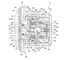
- the hydraulic shock absorber according to the embodiment (hereinafter sometimes simply referred to as “absorber”) roughly includes a cylinder 10 as a cylinder device as shown in FIG. And an electromagnetic variable valve 12 (hereinafter, simply referred to as “variable valve 12”) as a variable valve mechanism.
- the cylinder 10 includes a housing 20, a piston 22 disposed so as to be movable in the vertical direction inside the housing 20, one end (lower end) connected to the piston 22, and the other end (upper end) at the housing 20. And a rod 24 extending upward.
- a connecting member 26 is attached to the lower end of the housing 20, and the housing 20 is a rod in which a male screw is formed on the lower part of the vehicle (for example, suspension lower arm, steering knuckle, etc.) via the connecting member 26.
- the upper end portion of each 24 is connected to a sprung portion of the vehicle (for example, a mount provided on the vehicle body) using the male screw. That is, the cylinder 10 is disposed so as to connect the sprung portion and the unsprung portion of the vehicle.
- the cylinder 10 expands and contracts as the upper and lower springs move relative to each other in the up-and-down direction, that is, with separation and approach. More specifically, when the spring upper part and the unsprung part move relative to each other (hereinafter sometimes referred to as “rebound operation” or “rebound operation”), the extension moves and moves relative to each other in the approaching direction. (Hereinafter, sometimes referred to as “bounding operation” or “bounding”).
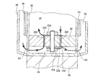
- the piston 22 is movable in sliding contact with the inside of the housing 20, and two liquid chambers 30 and 32 filled with the working fluid are defined by the piston 22 in the housing 20. More specifically, a rod side chamber 30 that is positioned above the piston 22 and through which the rod 24 penetrates, and an anti-rod side chamber 32 that is positioned below the piston 22 are partitioned.
- the volumes of the two liquid chambers 30 and 32 change with the expansion and contraction of the cylinder 10, that is, with the relative movement between the spring top and the spring bottom. Specifically, during the rebound operation, the volume of the rod side chamber 30 decreases and the volume of the anti-rod side chamber 32 increases. On the other hand, during the bounding operation, the volume of the rod side chamber 30 increases and the volume of the non-rod side chamber 32 decreases.
- the housing 20 generally has a triple structure, and has a bottomed main tube 36 present on the innermost peripheral side, an outer tube 38 attached to the outer peripheral portion of the main tube 36 and present on the outermost peripheral side, An intertube 39 is provided between the main tube 36 and the outer tube 38 so as to surround the tube 36.
- the periphery of the rod-side chamber 30 and the anti-rod-side chamber 32 is partitioned by the inner peripheral surface of the main tube 36, and is between the outer peripheral surface of the main tube 36 and the outer peripheral surface of the intertube 39 and the inner peripheral surface of the outer tube 38. Accordingly, the buffer chamber 40 for accommodating the working fluid is partitioned.
- the buffer chamber 40 functions as a reservoir for storing hydraulic fluid outside the rod side chamber 30 and the anti-rod side chamber 32, and can also be called a reservoir chamber. Due to the presence of the rod 24, the total volume of the rod side chamber 30 and the non-rod side chamber 32 increases when rebounding and decreases when bounding.
- the buffer chamber 40 is a liquid chamber provided to allow a change in the total volume in a state where the rod side chamber 30 and the anti-rod side chamber 32 are filled with the working fluid.
- a partition member 42 that partitions the bottom of the anti-rod side chamber 32 is provided at the inner bottom of the main tube 36, and a bottom liquid passage 44 is formed between the partition member 42 and the bottom wall of the main tube 36. ing. On the other hand, an annular liquid passage 54 is formed between the inner peripheral surface of the intertube 39 and the outer peripheral surface of the main tube 36.
- An upper flow hole 60 is provided in a portion near the upper end of the main tube 36 for the flow of the working fluid between the annular liquid passage 54 and the rod side chamber 30, and a portion near the lower end of the main tube 36 is provided. Is provided with a lower flow hole 64 for the flow of hydraulic fluid between the buffer chamber 40 and the bottom liquid passage 44.
- An outlet 72 that allows the hydraulic fluid to flow out from the annular fluid passage 54 is disposed below the intertube 39, and the outer tube 38 is disposed coaxially with the outlet 72, so that the hydraulic fluid to the buffer chamber 40 is disposed.
- An inflow port 76 that allows the inflow of is provided.
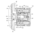
- the piston 22 is formed with a liquid passage connecting the rod side chamber 30 and the non-rod side chamber 32, and a first valve mechanism 78 is provided in the liquid passage.
- the first valve mechanism 78 is conceptually arranged as if a check valve 80 and a resistance applying mechanism 82 that provides resistance (first resistance) to the flow of hydraulic fluid in the flow path are arranged in series. The detailed structure will be described later.
- the partition member 42 is formed with a liquid passage connecting the anti-rod side chamber 32 and the bottom liquid passage 44, and a second valve mechanism 84 is provided in the liquid passage. ing.
- the second valve mechanism 84 has a configuration in which a check valve 86 and a resistance applying mechanism 88 that provides resistance (second resistance) to the flow of hydraulic fluid in the flow path are arranged in parallel. The detailed structure will be described later.
- variable valve 12 is disposed so as to cover the outlet 72 and the inlet 76, and allows the hydraulic fluid flowing into the buffer chamber 40 from the annular fluid passage 54 to pass therethrough. Has a function of giving a resistance (third resistance) to the flow of.
- the detailed structure of the variable valve 12 will be described later.
- the variable valve 12 is generally configured such that the magnitude of the resistance given to the hydraulic fluid passing through the variable valve 12 depends on the magnitude of the current supplied to itself. . Simply put, the magnitude of the resistance can be changed according to the current.
- the variable valve 12 is connected to a battery 92 (indicated as [BAT] in FIG. 1) via a controller 90 (indicated as [CNT] in FIG. 1) as a control device.
- the controller 90 controls the current supplied to the variable valve 12.
- the variable valve 12 includes a main valve 98 for providing resistance to the hydraulic fluid that passes through the variable valve 12.
- a hollow valve housing 102 provided with the flow path 100, a valve body (also referred to as “valve movable body”) 104 accommodated in the valve housing 102, a solenoid 106, and a spring that is a compression coil spring. 108 and a spring 110 which is a compression coil spring.
- the solenoid 106 has a function of applying an urging force in a direction to limit the flow path area to the valve body 104 constituting the main valve 98, and the spring 108 maximizes the flow path area to the valve body 104.
- the spring 110 has a function of applying a biasing force in the direction, and the spring 110 has a function of applying a biasing force in the direction of limiting the flow path area to the valve body 104.
- the variable valve 12 includes a fail valve 112 disposed in series with the main valve 98 in the middle of the flow path 100.
- the valve housing 102 includes a horizontal hole 114 extending along the axis of the variable valve 12 and a vertical hole 116 communicating with the horizontal hole 114, and the outer periphery of the tip that is the left end in FIG. A sleeve 118 provided at the outlet 72 is fitted. As a result, the left end opening of the horizontal hole 114 is exposed to the annular liquid passage 54 formed between the main tube 36 and the inter tube 39, and the vertical hole 116 is exposed to the buffer chamber 40.
- the flow path 100 is formed including the horizontal holes 114 and the vertical holes 116.
- valve housing 102 is provided with a small inner diameter portion 120 in the middle of the horizontal hole 114, more specifically, on the annular liquid passage 54 side (left side in FIG. 2) of the vertical hole 116.
- An annular valve seat 122 is formed by the inner edge of 120.
- the valve housing 102 has, on the outer periphery, a flange 124 on the annular liquid passage 54 side (left side in FIG. 2) from the opening of the vertical hole 116, and the opposite side of the annular liquid passage 54 from the opening of the vertical hole 116.
- a large outer diameter portion 126 is provided on the right side in FIG.
- a seal ring 128 is attached to the outer periphery of the fitting portion of the valve housing 102 to the sleeve 118, and the space between the annular liquid passage 54 and the buffer chamber 40 is sealed.
- the liquid passage 54 and the buffer chamber 40 are not communicated with each other.
- the flange 124 of the valve housing 102 is fitted to the inner periphery of the cylinder 130 attached to the inlet 76 of the outer tube 38 and is in contact with a step portion 132 provided on the inner periphery of the cylinder 130.
- the tube 130 includes a screw portion (not shown) on the outer periphery of the end portion, and a bottomed cylindrical case 134 including the solenoid 106 is screwed to the tube 130.
- the case 134 is disposed on the inner side of the cylindrical portion 136, the bottom portion 138 that is fixed by crimping the opening end of the cylindrical portion 136, and the coil 140 of the solenoid 106. And an inner flange 144 for holding a solenoid bobbin 142 for holding the same.
- the inner flange 144 and the stepped portion 132 of the cylinder 130 sandwich the flange 124 of the valve housing 102 and the nonmagnetic spacer 146, thereby fixing the valve housing 102 to the cylinder 10.
- a through-hole 148 is formed in the flange 124 so that the communication with the buffer chamber 40 of the flow path 100 is not cut off by the flange 124 even if fixed in this way.
- the solenoid 106 includes the above-described bottomed cylindrical case 134, the annular solenoid bobbin 142 that holds the coil 140 and is fixed to the bottom of the case 134, and the bottomed cylindrical inner periphery of the solenoid bobbin 142.
- the first fixed iron core 150 fitted on the inner periphery of the solenoid bobbin 142 and the cylindrical second fixed iron core 152 fitted on the inner circumference of the solenoid bobbin 142, and the first fixed iron core 150 fitted on the inner circumference of the solenoid bobbin 142.
- the bottomed cylindrical movable iron core 156 is slidably inserted into the inner periphery of the first fixed iron core 150 with the opening end side of the cylinder facing the inner side of the first fixed iron core 150, and the first The bottom side surface (the left surface in FIG. 2) of the second fixed iron core 152 remains even if it enters the first fixed iron core 150 until it contacts the nonmagnetic washer 160 disposed on the bottom of the fixed iron core 150. It is arranged so as to be slightly opposite or close to the inner periphery. Further, a through hole 162 is provided in the peripheral wall of the cylinder of the movable iron core 156 so that the space defined by the first fixed iron core 150 and the movable iron core 156 is not sealed.
- the above-described spring 110 is interposed between the movable iron core 156 and the first fixed iron core 150, and an urging force in a direction away from the first fixed iron core 150 is given to the movable iron core 156 by the spring 110.
- the spring 110 is supported by a spring receiver 166 provided at the tip of a spring force adjusting screw 164 whose right end in FIG. 2 is screwed to the shaft core portion of the first fixed iron core 150, and the spring force adjusting screw 164 is attached to the first fixed iron core.
- the support position of the spring 110 can be changed to the left and right in FIG.
- the second fixed iron core 152 has a cylindrical shape, and the opening end on the first fixed iron core 150 side has a tapered shape such that the outer peripheral portion is inclined, and magnetic flux generated when the coil 140 is energized. 2 is concentrated on the inner peripheral side of the right end, and the shape of the left end in FIG. 2 of the non-magnetic spacer 154 interposed between the second fixed iron core 152 and the first fixed iron core 150 is The shape is matched with the taper of the two fixed iron cores 152.
- the solenoid 106 has a magnetic path as shown by an arrow in FIG. 3, more specifically, a magnetic circuit that goes around the first fixed iron core 150, the movable iron core 156, and the second fixed iron core 152. A path is formed.
- the coil 140 is energized and the solenoid 106 is excited, that is, when a current is supplied to the damping force generator 12, the movable iron core 156 disposed near the first fixed iron core 150 is moved to the second fixed iron core 152 side.
- a suction force in the direction toward the left side in FIG. 2 acts on the movable iron core 156 by suction.
- the bottom of the movable iron core 156 is in contact with the valve body 104 constituting the main valve 98, so that the urging force of the spring 110 is transmitted to the valve body 104. Further, when the solenoid 106 is excited, a biasing force in the direction toward the left side in FIG. 2 is applied to the valve body 104 through the attracted movable iron core 156.
- the movement of the movable iron core 156 to the valve body 104 side (left side in the figure) is a non-magnetic material that is fitted to the outer periphery of the right end of the valve housing 102 and whose leftward movement is restricted by the large outer diameter portion 126. It is regulated by a cylindrical stopper 168 made of That is, the limit of movement is defined.
- the valve body 104 extends from the left end of the large-diameter portion 170 slidably contacting the inner periphery of the right end of the valve housing 102 in FIG. 2 and faces the vertical hole 116 of the valve housing 102.
- a small-diameter portion 172 and a poppet-type valve head 174 formed at the left end of the small-diameter portion 172 are configured, and the valve head 174 can be opened and closed by being seated on and off the valve seat 122. It has become.
- a gap is formed between the outer peripheral surface of the small diameter portion 172 and the inner peripheral surface of the valve housing 102, and the valve body 104 may block the vertical hole 116. There are no considerations.
- the spring 108 described above is interposed between the left end of the large diameter portion 170 in the valve body 104 and the right end of the small inner diameter portion 120 of the valve housing 102, and the spring 108 is attached to the valve body 104.
- the biasing force in the direction away from the valve seat 122 that is, the biasing force in the direction that maximizes the channel area of the channel 100 is applied.
- valve body 104 is sandwiched between the spring 108 and the spring 110 via the movable iron core 156, and a biasing force in the direction that maximizes the flow path area of the flow path 100 is given by the spring 108.
- a biasing force in a direction of restricting the flow path of the flow path 100 is applied by the spring 110 via the movable iron core 156.
- the spring 108 and the spring 110 are arranged in series as described above, if the support position of the spring 110 is adjusted by the spring force adjusting screw 164, the length of the spring 110 in the compressed state, In other words, not only can the compression length be changed, but also the compression length of the spring 108 can be adjusted, and the biasing force that the springs 108 and 110 apply to the valve body 104, in particular, the current is supplied to the solenoid 106. It is possible to adjust the standard urging force that is the urging force in the absence state.
- the position of the valve body 104 with respect to the amount of current supplied to the solenoid 106 (which can be considered as the amount of current supplied to the damping force generator 12), that is, the flow path in the valve mechanism 98.
- the area can be adjusted.
- the second fixed iron core 152 of the solenoid 106 protrudes to the left in FIG. 2 from the solenoid bobbin 142, and a spacer 146 is fitted to the outer periphery of the left end of the second fixed iron core 152.
- the spacer 146 has a cylindrical shape and is provided with an inner flange 176 on the inner periphery of the right end.
- the outer periphery of the second fixed iron core 152 is fitted to the inner periphery of the inner flange 176.
- the spacer 146 is also fitted to the inner periphery of the cylinder 130 provided in the outer tube 38, and the space between the spacer 146 and the cylinder 130 is sealed by a seal ring 178 attached to the outer periphery of the spacer 146. .
- the fail valve 112 is interposed between the fail valve body 158 slidably mounted on the outer periphery of the large outer diameter portion 126 of the valve housing 102, and the fail valve body 158 and the inner flange 176 of the spacer 146. And a spring 180 that is a compression coil spring that functions as a fail elastic body.
- the fail valve 112 is a valve that functions when no electric power is supplied to the damping force generator 12, in other words, when the coil 140 of the solenoid 106 is not energized. It is designed to work in the event of a major failure. That is, the fail valve 112 is named based on such a function.
- the fail valve body 158 has a generally cylindrical shape, and includes a flange 182 provided on the outer peripheral side, an annular protrusion 184 facing the right end surface of the flange 124 of the valve housing 102 in FIG. 2, and an inner periphery and an outer periphery. An orifice 186 that communicates, and a through hole 188 that opens from the right end in FIG. 2 and communicates with the orifice 186 are provided.
- the fail valve body 158 is constantly urged toward the flange 124 side of the valve housing 102 by a spring 180 interposed between the flange 182 and the inner flange 176 of the spacer 146.
- the right end of the fail valve body 158 faces the left end of the second fixed iron core 152, and as shown in FIG. 3, the magnetic path is the second fixed iron core 152, the fail valve body 158, the valve housing 102, the cylinder. 130 and case 134 are formed. From the above, in the solenoid 106, when the coil 140 is excited, the fail valve body 158 is attracted to the second fixed iron core 152, and the right urging force in FIG. 2 acts on the fail valve body 158. It is supposed to be.
- the urging force that acts on the fail valve body 158 by the solenoid 106 overcomes the urging force of the spring 180, and the fail valve body 158 is adsorbed to the second fixed iron core 152. As a result, the channel 100 is opened to the maximum.
- the urging force acting on the fail valve body 158 by the solenoid 106 cannot overcome the urging force by the spring 180, and the fail valve body 158
- the annular protrusion 184 is located at a position where it comes into contact with the flange 124 of the valve housing 102.
- the flow path area is limited.
- the orifice 186 of the fail valve body 158 faces the flow channel 100 and the flow channel 100 communicates only through the orifice 186, so the flow channel area is the flow channel area of the orifice 186. It is limited to.
- the fail valve 112 when the supply current to the solenoid 106 exceeds the threshold value, the fail valve 112 is in an open position for opening the flow path 100. Conversely, in a state where the supply current to the solenoid 106 does not exceed the threshold value, The fail position is such that the flow path 100 communicates only through 186.
- variable valve 12 when no current is supplied to the solenoid 106, that is, when no current is supplied to the variable valve 12, only through the flow path 100 and the orifice 186. Therefore, it can be considered that a liquid passage (sub-liquid passage) including the liquid passage communicating with the flow passage 100 is formed, and resistance is given to the flow of the working fluid passing through the sub-liquid passage.
- the flow of the hydraulic fluid passing through the variable valve 12 is configured to give a certain amount of resistance.
- the resistance may be hereinafter referred to as “third resistance when no current is supplied”.
- variable valve 12 when a current exceeding the threshold is supplied to the solenoid 106, that is, when a current exceeding the threshold is supplied to itself, the flange 124 of the valve housing 102 and the fail valve body 158 It can be considered that a liquid passage (main liquid passage) including a liquid passage that communicates the flow path 100 with the annular protrusion 184 is formed, and the working fluid that passes through the main liquid passage.
- a liquid passage main liquid passage
- resistance resistance is provided to the flow of hydraulic fluid that passes through the variable valve 12. More specifically, the flow path 100 is provided with the above-described main valve 98, and resistance is given to the flow of hydraulic fluid passing between the valve seat 122 and the valve body 104 constituting the main valve 98. It is done.
- the magnitude of this resistance depends on the size of the gap between the valve seat 122 and the valve body 104, that is, the degree of opening of the main valve 98.
- the urging force that the solenoid 104 applies to the valve body 104 depends on the magnitude of the current supplied to the solenoid 104. Due to the structure of the main valve 98 described above, the greater the current, the greater the degree of valve opening. Lower. That is, it becomes difficult to open the valve. Therefore, as the supplied current increases, the resistance given to the flow of hydraulic fluid passing through the main liquid passage increases. From the above, the variable valve 12 has a resistance corresponding to the magnitude of the current with respect to the flow of the hydraulic fluid passing through the variable valve 12 when a current exceeding the threshold value is supplied. The resistance is increased as the current increases. Incidentally, the resistance may be hereinafter referred to as “current dependent resistance”.
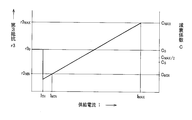
- the resistance (hereinafter sometimes referred to as “third resistance r3”) may be referred to as a supplied current (hereinafter referred to as “supply current”). )
- supply current a supplied current
- the third resistor r3 is until the supply current I exceeds the threshold I TH, the current non-supply time of the third resistor r3 0 becomes, if it becomes more than the threshold value I TH, as the supply current I increases growing.
- the variable valve 12 is normally supplied with the current I in the set range, specifically, the current I between the lower limit current I MIN and the upper limit current I MAX.
- the variable valve 12 is supplied with the supply current I larger than a predetermined value In this case, it can be considered that the third resistor r3 having a magnitude corresponding to the magnitude of the supply current I is provided.
- variable valve 12 is configured such that the third resistance r3 0 becomes a value between the lower limit resistance r3 MIN and the upper limit resistance r3 MAX when no current is supplied.
- the current non-supply time of the third resistor r3 0, in the absorber of the present embodiment, is greater than the lower resistance r3 MIN variable valve 12 will give in the case where the lower limit current I MIN as set values supplied.
- the lower limit current I MIN is set slightly larger than the threshold value I TH . That is, a certain margin with respect to the threshold value I TH is provided in the lower limit current I MIN .
- the supply current to the solenoid 106 may become oscillating or insufficient due to instability of the voltage of the battery 92, noise, or the like, and the current I having a magnitude close to the lower limit current I MIN is supplied.
- the third resistance r3 changes suddenly when the fail valve 112 is switched to the fail position. In view of this, the margin is provided.
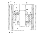
- the piston 22 is provided with a first liquid passage 200 and a second liquid passage 202 that penetrate the piston 22 in the axial direction.
- the two leap springs 206 and 208 sandwiched between the piston 22 and the nut 204 on the end surface defining the rod-side chamber 30 of the piston 22 with respect to the second liquid passage 202 are the anti-rod-side chamber 32 of the piston 22.
- Three leap springs 212, 214, and 216 sandwiched between the piston 22 and the nut 210 are respectively disposed on the end face that divides.
- the first valve mechanism 78 described above includes an opening end of the first liquid passage 200 and leaf springs 206 and 208 that close the opening end.
- the leaf springs 206 and 208 functioning as valve plates block the first liquid passage 200, and the flow of hydraulic fluid from the rod side chamber 30 to the anti-rod side chamber 32 is prohibited by the leaf springs 206 and 208.
- the flow of hydraulic fluid from the anti-rod side chamber 32 to the rod side chamber 30 is allowed against the elastic reaction force of the leaf springs 206 and 208. Therefore, the leaf springs 206 and 208 function as the check valve 80 shown in FIG. 2 and the resistance applying mechanism 82 shown in FIG. 2 with respect to the flow of the hydraulic fluid passing through the first liquid passage 200. It is said that.
- the first liquid passage 200 functions as a first communication passage that allows the rod side chamber 30 and the anti-rod side chamber 32 to communicate with each other, and a first passage provided in the first communication passage.
- the valve mechanism 78 prohibits the flow of hydraulic fluid from the rod side chamber 30 to the anti-rod side chamber 32, and gives the first resistance r1 to the flow of hydraulic fluid from the anti-rod side chamber 32 to the rod side chamber 30. However, it is allowed.
- the second liquid passage 202 also communicates the rod side chamber 30 and the anti-rod side chamber 32, and the leap springs 212, 214, and 216 that close the second liquid passage 202 also have another valve mechanism. It is what constitutes. However, the leap springs 212, 214, and 216 that function as valve plates are allowed to allow only a considerably strong flow of hydraulic fluid. Therefore, the valve mechanism does not function normally, and for example, the operation from the rod side chamber 30 to the anti-rod side chamber 32 is performed only when a structural failure or the like that causes an abnormality in the flow of the hydraulic fluid occurs. The liquid flow is allowed.
- the partition member 42 is provided with a first liquid passage 220 and a second liquid passage 222 that penetrate the partition member 42 in the axial direction.
- a single leap spring 226 sandwiched between the partition member 42 and the nut 224 is attached to the end surface of the partition member 42 that divides the anti-rod side chamber 32 with respect to the second liquid passage 222.
- Two leap springs 230 and 232 sandwiched between the partition member 42 and the nut 228 are disposed on end faces that define the liquid passage 44.
- the above-described second valve mechanism 84 includes open ends of the first liquid passage 200 and the second liquid passage 202, and leaf springs 226 and leaf springs 230 and 232 that close them. ing.
- the leaf spring 226 functioning as a valve plate blocks the first liquid passage 220, and the flow of hydraulic fluid from the anti-rod side chamber 32 to the bottom liquid passage 44 is prohibited by the leaf spring 226.
- the flow of hydraulic fluid from the bottom liquid passage 44 to the anti-rod side chamber 32 is allowed to resist the elastic reaction force of the leaf spring 226.
- the elastic reaction force of one leaf spring 226 is considerably small, and the leaf spring 226 does not substantially resist the flow of the hydraulic fluid. Therefore, the leaf spring 226 functions as the check valve 86 shown in FIG. 2 with respect to the flow of the hydraulic fluid passing through the first liquid passage 200.
- the leaf springs 230 and 232 functioning as valve plates block the second liquid passage 222, and the flow of hydraulic fluid from the bottom liquid passage 44 to the anti-rod side chamber 32 is prohibited by the leaf springs 230 and 232.
- the flow of hydraulic fluid from the anti-rod side chamber 32 to the bottom liquid passage 44 is allowed to resist the elastic reaction force of the leaf springs 230 and 232. Therefore, the leaf springs 230 and 232 function as the resistance applying mechanism 88 shown in FIG. 2 with respect to the flow of the hydraulic fluid passing through the second liquid passage 222.
- the liquid passage formed by the lower flow hole 64 provided in a portion near the lower end of the main tube 36 functions as a second communication passage for communicating the anti-rod side chamber 32 and the buffer chamber 40, and the second communication passage.
- the second valve mechanism 84 provided in the passage allows the flow of the hydraulic fluid from the buffer chamber 40 to the anti-rod side chamber 32 so as not to substantially resist the flow, and from the anti-rod side chamber 32. The flow of the hydraulic fluid to the buffer chamber 40 is allowed while giving the second resistance r2 to the flow.
- the cylinder 10 having the above-described structure is disposed so as to connect the sprung portion and the unsprung portion of the vehicle, and as shown in FIG. It expands and contracts, that is, expands and contracts with relative movement. And with the expansion and contraction, the volumes of the rod side chamber 30 and the anti-rod side chamber change. As shown by a two-dot chain line in FIG. 2, if the cross-sectional area Ar of the rod side chamber 30 and the cross-sectional area Aa of the non-rod side chamber 32 are compared, The sectional area Ar of the side chamber 30 is smaller than the sectional area Aa of the anti-rod side chamber 32.
- the volume change amount ⁇ Vr of the rod-side chamber 30 becomes smaller than the volume change amount ⁇ Va of the non-rod-side chamber 32 when the amount is expanded or contracted by a certain amount.
- a buffer chamber 40 is provided to compensate for the difference between the volume change amount ⁇ Vr and the volume change amount ⁇ Va, and the rod side chamber 30 and the anti-rod side chamber 32 are provided as the cylinder 10 expands and contracts. And the buffer chamber 40, the working fluid flows in and out.
- the cylinder 10 When the spring top and the spring bottom move relative to each other, that is, during the rebound operation, the cylinder 10 extends, the volume Vr of the rod side chamber 30 decreases, and the volume Va of the non-rod side chamber 32 increases. .
- the function of the first valve mechanism 78 causes the working fluid to flow from the rod side chamber 30 to the non-rod side chamber 32 through the first liquid passage 200 provided in the piston 22, that is, through the first communication passage. Since the flow is prohibited, as shown by the solid line arrow in FIG. 2, the hydraulic fluid corresponding to the volume increase amount ⁇ Va of the non-rod side chamber 32 flows into the lower flow hole 64, the bottom liquid passage 44, and the first liquid passage.
- the upper flow hole 60 and the annular liquid passage 54 function as a third communication passage that allows the rod side chamber 30 and the buffer chamber 40 to communicate with each other, and the third communication passage is defined by the variable valve 12 provided in the third communication passage.
- the third resistance r3 is given to the flow of hydraulic fluid that passes through, that is, the flow of hydraulic fluid that passes through the variable valve 12 itself. As a result, the absorber of this embodiment generates a damping force determined by the third resistance r3 for the rebound operation.
- the damping force generated during the rebound operation is the damping coefficient C, which is the damping force generation characteristic of the absorber during the rebound operation, according to the magnitude of the third resistor r3.
- the third resistor r3 can be changed according to the magnitude of the supply current I. Since the third resistance r3 can be changed within the range shown in FIG. 4, the attenuation coefficient C can be changed similarly.
- FIG. 4 also shows the change of the attenuation coefficient C. According to this figure, the absorber will reduce the attenuation coefficient C to the minimum attenuation corresponding to the lower limit resistance r3 MIN according to the supply current I.
- the absorber of the present embodiment in the case as described above, the current non-supply time of the third resistor r3 0, because they are larger than the lower resistance r3 MIN, the current to the variable valve 12 is not supplied
- the current non-supply attenuation coefficient C 0 that is the attenuation coefficient C is larger than the minimum attenuation coefficient C MIN .
- the absorber according to the present embodiment can generate a certain amount of damping force against the rebound operation even in the case of electrical failure. It has become.
- the cylinder 10 contracts, the volume Vr of the rod side chamber 30 increases, and the volume Va of the non-rod side chamber 32 increases. Decrease.
- the flow of the hydraulic fluid from the non-rod side chamber 32 to the rod side chamber 30 through the first communication path causes the flow of the first resistance as shown by the broken arrow in FIG.
- the operation from the non-rod side chamber 32 to the buffer chamber 40 via the second communication passage is permitted in the state where r1 is given and, as indicated by the broken arrow in FIG.
- the liquid flow is allowed in the state where the second resistance r2 is given.
- the first resistance r1 and the second resistance r2 cause the amount of hydraulic fluid corresponding to the volume increase amount ⁇ Vr of the rod side chamber 30 to pass from the anti-rod side chamber 32 to the rod side chamber via the first communication path. 30 and the amount of hydraulic fluid commensurate with the amount obtained by subtracting the volume increase amount ⁇ Vr of the rod side chamber 30 from the volume decrease amount ⁇ Va of the anti-rod side chamber 32 from the anti rod side chamber 32 through the second communication path.
- the magnitude of the first resistor r1 and the magnitude of the second resistor r2 are adjusted so as to flow through Specifically, the rigidity of the leaf springs 206 and 208 and the leaf springs 230 and 232 is adjusted.
- the absorber of the present embodiment generates a damping force determined by the magnitude of the first resistance r1 and the magnitude of the second resistance r2 for the bound operation.
- the damping force generated during the bounding operation is, in other words, the damping coefficient C, which is the damping force generation characteristic of the absorber during the bounding operation, is fixed according to the magnitude of the first resistance r1 and the magnitude of the second resistance r2. It will be something like that. Assuming that the fixed damping coefficient C is the contraction damping coefficient C S , in the absorber of the present embodiment, the contraction damping coefficient C S is smaller than the maximum damping coefficient C MAX as shown in FIG. Specifically, the maximum attenuation coefficient C MAX is set to be 1 ⁇ 2 or less.
- the absorber according to the present embodiment is configured so that the damping force when the cylinder 10 contracts becomes the maximum when the third resistance r3 is maximum within the set range, that is, when the third resistance r3 is the upper limit resistance r3 MAX. More specifically, it is configured to be less than or equal to 1 ⁇ 2 of the damping force so as to be smaller than the damping force when 10 is extended. Further, in the absorber of the present embodiment, the contraction damping coefficient C S is set to be not less than the minimum damping coefficient C MIN as shown in FIG.
- the absorber according to the present embodiment is configured so that the damping force when the cylinder 10 contracts becomes smaller when the third resistance r3 becomes the minimum within the set range, that is, when the third resistance r3 becomes the lower limit resistance r3 MIN. It is comprised so that it may become more than the damping force at the time of 10 extending
- control of the absorber of this embodiment that is, the control of the variable valve 12 is not particularly limited, but here, the main purpose is to suppress the vibration of the sprung portion.
- the control of this absorber will be described by taking “sprung vibration damping control” as an example of the control to be performed.
- sprung mass damping control This absorber generates a damping force for the relative movement of the sprung portion and the sprung portion.
- the sprung mass damping control is specially used for damping the sprung portion. This is control for generating and generating.
- the sprung mass damping control is a control that changes according to the sprung speed in order to damp the vibration of the vehicle body. In short, as the sprung speed increases, the damping force, that is, the damping coefficient C increases. It is control to do.
- the absorber In the sprung mass damping control, when the sprung portion is moving upward, the absorber should generate a force in the direction toward the lower portion of the sprung portion. When moving, the absorber should generate a force against the sprung in the direction in which it moves downward. However, when a bounce operation is performed while the sprung portion is moving upward, and when a rebound operation is performed while the sprung portion is moving downward, the force generated by the absorber (hereinafter referred to as “absorber”). Force ”) may act in a direction that promotes the movement of the sprung.
- aborber the force generated by the absorber
- FIG. 7 is a graph showing changes in the sprung speed v S and the unsprung relative speed v S / US when the vehicle vibrates.
- the sprung speed v S is indicated by a solid line
- the sprung unsprung relative speed v S / US is indicated by a broken line.
- the region indicated by “*” is a region where the absorber force acts in the direction that promotes the movement of the sprung, and in some of the regions, the relatively large absorber force drives the movement of the sprung portion. It can be understood that it works.
- the absorber force acts in the direction of promoting the movement of the sprung portion, it is desirable to make the force relatively small. For this reason, when performing sprung mass damping control, the relative movement between the sprung portion and the unsprung portion is desirable.
- the direction of is switched, it is necessary to largely change the absorber force.
- the absorber force is to be greatly changed by changing the supply current I to the variable valve 12, for example, when the direction of relative movement between the sprung portion and the unsprung portion is switched, that is, when the reversal is accurately performed.
- the timing of the change is not always appropriate because it is difficult to grasp. Simply put, there will be a delay due to control.
- the shock absorber according to the present embodiment since the shock absorber according to the present embodiment has the above-described structure, it does not depend on the control of the supply current I to the variable valve 12, but depends on the structure, and the absorber force when the cylinder 10 extends. And the absorber force at the time of contraction are appropriately switched. Therefore, the absorber of the present embodiment is an absorber suitable for sprung mass damping control.
- the sprung part is provided with a sprung acceleration sensor for detecting vertical acceleration (hereinafter sometimes referred to as “sprung acceleration”) of the sprung part.
- the sprung speed v S is acquired based on the detected value.
- the movement direction of the sprung portion is specified by the value of the sprung speed v S , and the action of the above-described absorber is different between the case where the sprung portion is moved upward and the case where the sprung portion is moved downward. ,
- the supply mode of the supply current I to the variable valve 12 is switched.
- This absorber can perform good sprung mass damping control by using the above-described action and controlling the variable valve 12 under the action.
- variable valve control program The controller 90 is configured with a computer as a main component, and the control of the variable valve 12 is relatively short by the controller 90 using the variable valve control program shown in the flowchart of FIG. This is performed by repeatedly executing at a time pitch (for example, several tens of milliseconds). Below, the flow of the process according to the said program is demonstrated along the flowchart.
- the sprung speed v S is acquired based on the detection value of the sprung acceleration sensor in S1 (“S” means step), and in S2, the sprung speed v It is determined whether or not the value of S is positive, that is, whether or not the sprung portion has moved upward.
- the sprung between the lower limit current I MIN and the upper limit current I MAX is determined based on the acquired sprung speed v S.
- the supply current I is determined so as to increase as the speed v S increases.
- the supply current I is determined to be the lower limit current I MIN .
- good sprung mass damping control can be performed by executing the simple program as described above without recognizing a change in the direction of relative movement between the sprung portion and the unsprung portion. It is. In other words, good sprung mass damping control can be performed by performing simple processing without obtaining the sprung unsprung relative speed v S / US .
- variable valve 12 is configured such that the third resistance r3 0 is larger than the lower limit resistance r3 MIN when no current is supplied.
- a variable valve 12 having the configuration it is possible to employ a variable valve third resistor r3 0 when the current non-supply is configured to be equal to or less than the lower limit resistor r3 MIN. That is, the variable valve absorber modification is employed, the resistance r3 0 of a certain size to be applied to the case where no current is supplied, and a third resistor r3 below gives in when the current I of the set value is supplied to it It can also be configured as follows. Specifically, the orifice 186 shown in FIG.
- variable valve 2 may be adjusted so that the cross-sectional area of the flow path becomes large.
- a variable valve it is also possible to construct a variable valve in which the third resistance r3 0 is equal to the lower limit resistance r3 MIN as a set value when no current is supplied.
- the third resistance r3 changes according to the change of the supply current I.
- variable valve in which the third resistance r3 is changed is used as shown in FIG. 10, when the variable valve is controlled to perform the sprung mass damping control, when the sprung portion is moving downward, the variable valve
- the attenuation coefficient C can be set to the minimum attenuation coefficient C MIN without supplying current to.
Landscapes
- Engineering & Computer Science (AREA)
- General Engineering & Computer Science (AREA)
- Mechanical Engineering (AREA)
- Physics & Mathematics (AREA)
- Electromagnetism (AREA)
- Fluid-Damping Devices (AREA)
- Vehicle Body Suspensions (AREA)
Abstract
L'invention concerne un amortisseur hydraulique comprenant un vérin (10) et une soupape variable (12), apte à modifier une force d'amortissement par la commande de ladite soupape variable (12), et ayant disposés à l'intérieur de ce dernier: un premier mécanisme de soupapes (78) qui permet un écoulement de fluide hydraulique vers une chambre côté tige (30) à partir d'une chambre (32) sur le côté opposé à la tige, dans un état dans lequel une première résistance est appliquée; et un second mécanisme de soupapes (84) qui permet un écoulement de fluide hydraulique vers une chambre tampon (40) à partir de la chambre sur le côté opposé à la tige, dans un état dans lequel une seconde résistance est appliquée. L'amortisseur hydraulique règle les première et seconde résistances, de telle sorte que lorsque le vérin rentre, une quantité de fluide hydraulique correspondant à l'augmentation de capacité dans la chambre côté tige s'écoule de la chambre sur le côté opposé à la tige à la chambre côté tige, et de telle sorte qu'une quantité de fluide hydraulique s'écoule de la chambre sur le côté opposé à la tige à la chambre tampon, ladite quantité correspondant à la quantité de l'augmentation de capacité dans la chambre côté tige a diminué en résultat de la diminution de capacité de la chambre sur le côté opposé à la tige. L'amortisseur hydraulique est apte à effectuer des changements relativement importants de la force d'amortissement lorsque le vérin est amené de la position sortie à la position rentrée, sans s'appuyer sur la commande de soupape variable, en résultat du fait qu'il est apte à générer une force d'amortissement fixe pendant la contraction.
Priority Applications (1)
| Application Number | Priority Date | Filing Date | Title |
|---|---|---|---|
| PCT/JP2013/063249 WO2014184836A1 (fr) | 2013-05-13 | 2013-05-13 | Amortisseur hydraulique |
Applications Claiming Priority (1)
| Application Number | Priority Date | Filing Date | Title |
|---|---|---|---|
| PCT/JP2013/063249 WO2014184836A1 (fr) | 2013-05-13 | 2013-05-13 | Amortisseur hydraulique |
Publications (1)
| Publication Number | Publication Date |
|---|---|
| WO2014184836A1 true WO2014184836A1 (fr) | 2014-11-20 |
Family
ID=51897857
Family Applications (1)
| Application Number | Title | Priority Date | Filing Date |
|---|---|---|---|
| PCT/JP2013/063249 Ceased WO2014184836A1 (fr) | 2013-05-13 | 2013-05-13 | Amortisseur hydraulique |
Country Status (1)
| Country | Link |
|---|---|
| WO (1) | WO2014184836A1 (fr) |
Citations (4)
| Publication number | Priority date | Publication date | Assignee | Title |
|---|---|---|---|---|
| JPH05180259A (ja) * | 1991-12-27 | 1993-07-20 | Kayaba Ind Co Ltd | 減衰力調整式ショックアブソーバ |
| JP2009019715A (ja) * | 2007-07-12 | 2009-01-29 | Kayaba Ind Co Ltd | 油圧緩衝器 |
| JP2010101422A (ja) * | 2008-10-23 | 2010-05-06 | Aisin Seiki Co Ltd | ショックアブソーバ |
| JP2011185392A (ja) * | 2010-03-10 | 2011-09-22 | Kyb Co Ltd | 減衰弁 |
-
2013
- 2013-05-13 WO PCT/JP2013/063249 patent/WO2014184836A1/fr not_active Ceased
Patent Citations (4)
| Publication number | Priority date | Publication date | Assignee | Title |
|---|---|---|---|---|
| JPH05180259A (ja) * | 1991-12-27 | 1993-07-20 | Kayaba Ind Co Ltd | 減衰力調整式ショックアブソーバ |
| JP2009019715A (ja) * | 2007-07-12 | 2009-01-29 | Kayaba Ind Co Ltd | 油圧緩衝器 |
| JP2010101422A (ja) * | 2008-10-23 | 2010-05-06 | Aisin Seiki Co Ltd | ショックアブソーバ |
| JP2011185392A (ja) * | 2010-03-10 | 2011-09-22 | Kyb Co Ltd | 減衰弁 |
Similar Documents
| Publication | Publication Date | Title |
|---|---|---|
| JP6388701B2 (ja) | サスペンション制御装置 | |
| JP5034074B2 (ja) | 減衰力調整式流体圧緩衝器 | |
| US9855811B2 (en) | Vehicle suspension system | |
| JPWO2011099143A1 (ja) | サスペンション装置 | |
| US9469175B2 (en) | Shock absorber system | |
| CN103702888A (zh) | 铁道车辆用减震器 | |
| JP5136789B2 (ja) | 緩衝器 | |
| CN105683611A (zh) | 缓冲装置 | |
| CN105556163A (zh) | 缓冲装置 | |
| JP4487192B2 (ja) | ショック・アブソーバ用の制御可能なピストン・バルブおよび/またはボトム・バルブ | |
| CN105313632B (zh) | 减振系统 | |
| WO2014155662A1 (fr) | Amortisseur hydraulique | |
| JP2014144733A (ja) | 液圧式ショックアブソーバ | |
| JP2014163424A (ja) | 減衰力制御弁及びショックアブソーバ | |
| JP4426956B2 (ja) | 緩衝器 | |
| JP2015168337A (ja) | 車両用アブソーバシステム | |
| JP2011185392A (ja) | 減衰弁 | |
| JP2015140846A (ja) | 液圧式ショックアブソーバ | |
| JP2004308780A (ja) | 減衰力調整式緩衝器 | |
| KR100863721B1 (ko) | 감쇠력 가변 밸브 | |
| CN119687142A (zh) | 一种电磁阻尼调节阀 | |
| JP2016023776A (ja) | 車両用アブソーバシステム | |
| JPH07158683A (ja) | 油圧緩衝器 | |
| JP2015200345A (ja) | 車両用ショックアブソーバ | |
| KR20170067505A (ko) | 솔레노이드 밸브 |
Legal Events
| Date | Code | Title | Description |
|---|---|---|---|
| 121 | Ep: the epo has been informed by wipo that ep was designated in this application |
Ref document number: 13884574 Country of ref document: EP Kind code of ref document: A1 |
|
| NENP | Non-entry into the national phase |
Ref country code: DE |
|
| 122 | Ep: pct application non-entry in european phase |
Ref document number: 13884574 Country of ref document: EP Kind code of ref document: A1 |
|
| NENP | Non-entry into the national phase |
Ref country code: JP |