WO2014184865A1 - ピペット装置 - Google Patents
ピペット装置 Download PDFInfo
- Publication number
- WO2014184865A1 WO2014184865A1 PCT/JP2013/063392 JP2013063392W WO2014184865A1 WO 2014184865 A1 WO2014184865 A1 WO 2014184865A1 JP 2013063392 W JP2013063392 W JP 2013063392W WO 2014184865 A1 WO2014184865 A1 WO 2014184865A1
- Authority
- WO
- WIPO (PCT)
- Prior art keywords
- line
- pipette
- electric pipette
- absorbing material
- body case
- Prior art date
- Legal status (The legal status is an assumption and is not a legal conclusion. Google has not performed a legal analysis and makes no representation as to the accuracy of the status listed.)
- Ceased
Links
Images



Classifications
-
- B—PERFORMING OPERATIONS; TRANSPORTING
- B01—PHYSICAL OR CHEMICAL PROCESSES OR APPARATUS IN GENERAL
- B01L—CHEMICAL OR PHYSICAL LABORATORY APPARATUS FOR GENERAL USE
- B01L3/00—Containers or dishes for laboratory use, e.g. laboratory glassware; Droppers
- B01L3/02—Burettes; Pipettes
- B01L3/021—Pipettes, i.e. with only one conduit for withdrawing and redistributing liquids
- B01L3/0217—Pipettes, i.e. with only one conduit for withdrawing and redistributing liquids of the plunger pump type
- B01L3/0237—Details of electronic control, e.g. relating to user interface
-
- B—PERFORMING OPERATIONS; TRANSPORTING
- B01—PHYSICAL OR CHEMICAL PROCESSES OR APPARATUS IN GENERAL
- B01L—CHEMICAL OR PHYSICAL LABORATORY APPARATUS FOR GENERAL USE
- B01L3/00—Containers or dishes for laboratory use, e.g. laboratory glassware; Droppers
- B01L3/02—Burettes; Pipettes
- B01L3/021—Pipettes, i.e. with only one conduit for withdrawing and redistributing liquids
- B01L3/0217—Pipettes, i.e. with only one conduit for withdrawing and redistributing liquids of the plunger pump type
-
- B—PERFORMING OPERATIONS; TRANSPORTING
- B01—PHYSICAL OR CHEMICAL PROCESSES OR APPARATUS IN GENERAL
- B01L—CHEMICAL OR PHYSICAL LABORATORY APPARATUS FOR GENERAL USE
- B01L3/00—Containers or dishes for laboratory use, e.g. laboratory glassware; Droppers
- B01L3/02—Burettes; Pipettes
- B01L3/0286—Ergonomic aspects, e.g. form or arrangement of controls
-
- B—PERFORMING OPERATIONS; TRANSPORTING
- B01—PHYSICAL OR CHEMICAL PROCESSES OR APPARATUS IN GENERAL
- B01L—CHEMICAL OR PHYSICAL LABORATORY APPARATUS FOR GENERAL USE
- B01L2200/00—Solutions for specific problems relating to chemical or physical laboratory apparatus
- B01L2200/08—Ergonomic or safety aspects of handling devices
Definitions
- the present invention relates to a micropipette that is operated by hand, and more particularly, to an electrically operated micropipette.
- An electrically operated micropipette (hereinafter referred to as “electric pipette”) includes, for example, a cylinder in which a motor and a piston are inserted in a cylindrical main body case that is long in the vertical direction as disclosed in Patent Document 1.
- the piston in the cylinder moves up and down due to the drive of the motor, and the inside of the cylinder is negatively pressurized.
- a predetermined volume of liquid is sucked into and discharged from a chip attached to the tip of the main body case.
- a display / operation unit is provided on the base end side of the main body case, and capacity parameter setting, device operation mode setting, etc. are possible.
- an electric board for electrically controlling the motor in accordance with each setting, and a power supply battery for driving the electric board, the motor, and the like at a base end portion where the display unit / operation unit is provided.
- the main body case is provided with a release switch for removing the chip, and a finger rest serving as a support assist during operation and a stopper during non-operation.
- the present invention has been made based on the problems of the prior art, and its purpose is to increase the shock resistance against dropping of an electric pipette, to reduce the appearance damage of the equipment, the damage of the operation function, and thus the discharge of the equipment.
- An electric pipette that ensures the maintenance of performance is provided.
- an electric pipette houses a liquid suction / discharge mechanism that sucks and discharges liquid by moving a piston in a cylinder up and down, and is inserted into the liquid suction / discharge mechanism at a tip portion thereof.
- a vertically long cylindrical main body case with a chip to be detachably attached, with the chip mounting side down, an operation switch for operating the liquid suction / discharge mechanism, and the main body case gripped when operating the operation switch A hand grip part, a display / operation part that can set suction / discharge operation, a release switch for removing the tip, and a finger rest that serves as a support assist during operation and a stopper during non-operation,
- the external shape of the electric pipette designed with these components protrudes from the front, rear, left side, right side, and top surface on each side.
- a line connecting two or more site points is drawn, and an impact absorbing material is provided at at least one vertex of at least one of the front line, rear line, left side line, right side line, and top line. It is characterized by that.
- the electric pipette according to claim 2 is the electric pipette according to claim 1, wherein the display / operation unit is designed on a base end side of the main body case, and an impact absorbing material is provided on an upper surface of the electric pipette. It is characterized by being able to.
- the electric pipette according to claim 3 is the electric pipette according to claim 1 or 2, characterized in that an impact absorbing material is provided on an outer periphery of the lower end portion of the hand grip at the lower end portion of the hand grip portion. To do.
- the electric pipette according to claim 4 is the electric pipette according to any one of claims 1 to 3, wherein a surface on which the display / operation unit is designed is a front surface of the electric pipette, and the release switch is disposed on the front surface of the pipette. It is designed, and an impact absorbing material is provided on the upper surface of the release switch.
- the electric pipette according to claim 5 is the electric pipette according to any one of claims 1 to 4, wherein a surface on which the display / operation unit is designed is a front surface of the electric pipette, and the finger rest is on a rear surface of the pipette. It is designed, and an impact absorbing material is provided on the lower surface of the finger rest.
- An electric pipette is the electric pipette according to any one of the third to fifth aspects, wherein the left and right side surfaces of the electric pipette are protruding shapes that are electrically connected to the storage battery provided in the main body case. Charge points are provided, and on the left and right side surfaces of the main body case, an impact absorbing material that protrudes in the left-right direction from the charge points is provided.
- each part that is convex in the external shape of the electric pipette that is, at least one vertex on at least one fall prediction line that is expected to contact the floor when the electric pipette falls.
- the upper surface of the electric pipette is provided with an impact absorbing material not only at the apex, but also at the entire area, providing impact resistance. Will be improved.
- the lower part (tip part) of the electric pipette is attached with a detachable and soft tip, so that an impact absorbing material is provided over the entire lower end of the handgrip part to be protected when the tip is detached. , Impact resistance is further improved.
- release switch and finger rest are placed on the top of the front and rear lines, as well as the shock absorber on the top of the operation switch and the bottom of the finger rest where the pipetter's fingers come into contact.
- the operability due to the stopping effect and the fit can be improved.
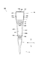
- FIG. 1 is a front view of an electric pipette showing an embodiment of the present invention
- FIG. 2 is a right side view of the electric pipette
- FIG. 3 is a rear view of the electric pipette
- FIG. 4 is a plan view of the electric pipette.
- symbols U and D indicate the pipette vertical direction
- symbols L and R indicate the pipette left-right direction
- symbols F and B indicate the pipette front-back direction.
- Reference numeral 100 denotes an electric pipette according to the present embodiment, which is a micropipette that is operated by hand to have an overall length of about 280 mm.
- Reference numeral 1 denotes a cylindrical main body case 1 that is long in the vertical direction, and a liquid suction / discharge mechanism 4 is accommodated in the case defined by fitting the front case and the rear case.
- the liquid suction / discharge mechanism 4 is connected to the piston 2 inserted in a cylinder 2 for sucking and discharging liquid, a piston 3 inserted in the cylinder 2 so as to be reciprocally movable in the vertical direction, and moves the piston 3 in the vertical direction.
- a motor 6 that is disposed above the ball screw mechanism 5 and that rotates the ball screw in both forward and reverse directions.
- Reference numeral 7 denotes a chip holder, which is a part of the main body case 1 and is engaged with the lower portion of the main body case 1 in a detachable manner. At the time of assembling, the lower side of the cylinder 2 that is formed to have a narrow diameter downward is accommodated.
- a tip 8 (illustrated by a broken line in FIG. 1) is provided at the lower end of the tip holder 7 so as to be detachably attached so as to be inserted through the lower end of the cylinder 2.
- the side on which the chip 8 is mounted that is, the lower direction of the main body case 1 is also referred to as the distal end portion 1t of the main body case 1, and the upper direction of the main body case 1 is also referred to as the base end portion 1b of the main body case 1.
- a display / operation unit 9 using a liquid crystal panel capable of setting liquid suction / discharge operation is provided above the front surface (front face) 100F of the electric pipette 100. Settings are possible.
- an electric board 10 that electrically controls the motor 6 according to each setting in the display / operation unit 9, and an electric board above the motor 6 are provided on the back surface of the display / operation unit 9.
- a power supply 11 for driving the motor 10 and the motor 6 is accommodated.
- a release switch 12 for removing the chip 8 is provided below the display / operation unit 9.
- the release switch 12 provided on the pipette front surface 100F is mechanically connected to the tip holder 7 so that the tip 8 is pushed down and released from the tip holder 7 by pressing the release switch 12 downward. It has become.
- the release switch 12 is formed in a button shape that protrudes forward of the electric pipette 100 so that the user can easily perform the push-down operation with a finger.
- An operation switch 14 for operating the liquid suction / discharge mechanism 4 is provided at a substantially central portion of the rear surface (back surface) 100B of the electric pipette 100.
- the operation switch 14 is impressed in the case, the motor 6 is driven, the ball screw 5 is rotated, the piston 3 in the cylinder 2 is moved up and down, and the inside of the cylinder 2 is negatively pressurized, whereby the display / operation unit A liquid having a volume set in advance in 9 is sucked and discharged by the chip 8.
- the release switch 12 and the display switch 9 are located below the display / operation unit 9 in the main body case 1.
- a lower area of the operation switch 14 is a hand grip portion 15 that is a portion that is gripped during operation.
- a finger rest 16 is provided below the operation switch 14 as a support assist during operation and a stopper during non-operation.
- the finger rest 16 is a hook that protrudes to the rear side of the electric pipette 100 and is bent downward so that when the user grips the hand grip portion 15, a finger other than the finger that operates the operation switch 14 is easily applied. It is formed into a shape.
- the above configuration is a design that can also be found in conventional electric pipettes, but in this way, an electric pipette is different from a box shape like a general measuring instrument, and is slender and small enough to be held by hand. Also, there are unevenness considering the operation with the thumb and index finger, and it is difficult to design a shock absorbing structure.
- the components that appear in the external shape of the electric pipette 100 of the present embodiment are the main body case 1, the operation switch 14, the hand grip portion 15, the display / operation portion 9, the release switch 12, and the finger rest 16.
- the charge points 17L and 17R (to be described later)
- a line connecting two or more protruding part points is drawn. Then, each line is assumed to be a line expected to come into contact with the floor when dropped.
- the lower surface 100D of the electric pipette 100 becomes the tip holder 7, but since this portion is elongated, it is difficult to contact the floor when dropped.
- the tip holder 7 is often made of a fluororesin or the like and is elastic and light, the electric pipette 100 rarely falls from the lower surface 100D side, and it is determined that the probability of breakage is low. Therefore, in the present application, the fall prediction line is set as the front line LF, the rear line LB, the left side line LL, the right side line LR, and the upper side line LU, and at least one of these lines has an impact on at least one vertex.
- An absorbent material will be provided.
- a setting method for each line and a suitable position where the shock absorbing material is provided will be described in detail. In FIGS. 1 to 4, the shock absorbing material is shown by coloring.
- the electric pipette 100 of the present embodiment is formed with a rectangular shape on the main body case base end 1b side above the main body case 1 so that the display / operation unit 9, the electric board 10, and the power source 11 can be efficiently stored. Therefore, the upper surface line LU is drawn as a part point where the left end 1Ul and the right end 1Ur of the upper surface 100U of the electric pipette 100 protrude. And it is preferable to provide an impact-absorbing material at the left end 1Ul and the right end 1Ur of the pipette upper surface 100U that is the apex of the upper surface line LU.
- the front line LF projects the first front line LF1 connecting the main body case base end 1b and the release switch 12 and the release switch 12 and the lower end 15d of the handgrip unit 15 as a projecting point.
- the second front line LF2 connecting them was drawn as the part point.
- the rear surface line LB is a part point projecting the main body case base end 1b and the finger rest 16 and projecting the first rear line LB1 connecting these, the finger rest 16 and the hand grip lower end part 15d.
- a second rear surface line LB2 connecting them was drawn.
- the top end 16t of the finger rest 16 that is the vertex where the rear end 1Ub of the pipette upper surface 100U that is the vertex of the first rear surface line LB1 and the first rear surface line LB1 and the second rear surface line LB2 intersect, It is preferable to provide an impact absorbing material.
- the shock absorbing material for the tip portion 7b of the chip holder 7 which is the apex of the second front surface line LF2 may be omitted because the protection of the chip holder 7 may be omitted for the reason described above.
- the electric pipette 100 of the present embodiment employs a storage battery as the power source 11 of the pipette, and electrically connects the storage battery to an external charging device.
- projecting charge points 17L and 17R that are electrically connected to the storage battery 11 are provided on the right side surface 100R and the left side surface 100L of the pipette.
- the left and right charge points 17L and 17R correspond to the part points protruding on the left and right side surfaces 100L and 100R of the pipette.
- the right side surface 100R and the left side surface 100L of the electric pipette 100 (main body case 1) absorb shocks that are higher in the left and right directions than the left and right charge points 17L and 17R at positions around the left and right charge points 17L and 17R. It is preferable to provide a material. As a result, the protruding part point moves from the left and right charge points 17L, 17R to the shock absorber, and the right side line LR and the left side line LL do not contact the left and right charge points 17L, 17R.
- the right side line LR is a part point where the main body case base end 1b and the above-described shock absorbing material protrude, and the first right side line LR1 connecting these, the above-described shock absorbing material and the lower end of the hand grip.
- the part 15d was used as a projecting part point, and a second right side line LR2 connecting them was drawn.
- shock absorbers are provided on the right end 1Ur of the pipette upper surface 100U that is the apex of the first right side line LR1, and the right side 15dr of the handgrip lower end 15d that is the apex of the second right side line LR2. Is preferred.
- the left side line LL is the same as the right side line LR because the electric pipette 100 of the present embodiment has a bilaterally symmetric structure, and the body case base end portion 1b and the above-described shock absorber are projecting part points.
- the first left side line LL1 connecting these and the above-mentioned impact absorbing material and the hand grip lower end 15d are set as projecting site points, and the second right side line LL2 connecting these is drawn.
- shock absorbers are provided on the left end 1Ul of the pipette upper surface 100U that is the apex of the first left side line LL1 and the left side 15d of the handgrip lower end 15d that is the apex of the second left side line LL2. Is preferred.
- the pipette upper surface 100U is provided not only with the vertices 1Uf, 1Ub, 1Ul, and 1Ur, but also with an impact absorbing material in the entire region.
- the detachable and soft tip 8 is attached to the lower side of the electric pipette 100 of the present embodiment (the main body case tip 1t), a portion that is likely to come into contact with the floor when the tip 8 is detached.
- the protection of the chip holder 7 may be omitted for the reasons described above. Therefore, since the handgrip lower end 15d is a part to be protected, it is preferable that the handgrip lower end 15d is provided with an impact absorbing material not only in the above-described vertices 15Uf, 1Ul, 1Ur but also in the entire region (the entire outer periphery).
- the release switch 12 on which the thumb of the pipetter abuts the upper surface is provided with an impact absorbing material on the upper surface 12u of the release switch in addition to the top portion 12t that hits the apex of the front line LF.
- an impact absorbing material on the finger rest lower surface 16d in addition to the top portion 16t corresponding to the apex of the rear surface line LB on the finger rest 16 where the finger of the pipetter contacts the lower surface.
- the electric pipette 100 of the present embodiment has the shock absorbing material 201 on the entire surface of the pipette upper surface 100U and the shock absorbing material 202 on the outer periphery of the lower end portion 15d of the hand grip.
- the shock absorbers 203 and 204 for the left and right charge points 17L and 17R are disposed on the left and right side surfaces 100L and 100R of the pipette, the shock absorbers 205 are disposed on the release switch top portion 12t and the release switch top surface 12u,
- a shock absorber 206 is provided.
- the material of the shock absorbers 201 to 206 is preferably a synthetic resin having soft and moderate elasticity, such as silicone resin, fluorine rubber, urethane resin, and the like.
- the shock absorbers 201 to 206 are provided (attachment means to the main body case 1) by integrally forming the main body case 1 made of a resin material such as fluororesin or the like.
- Various means such as fitting and pasting can be considered.
- One example will be described with the configuration of the electric pipette 100 of the present embodiment.
- the impact absorbing material 201 provided on the pipette upper surface 100U is formed in a cover shape that covers the entire upper surface 100U and the side surface (outer periphery) of the main body case base end portion 1b, and the engagement boss formed on the rear surface of the impact absorbing material 201,
- the main body case 1 is mounted by engaging with an engagement hole formed on the upper surface of the case 1 and fitting it into the concave and convex portions.
- the shock absorbers 203 and 204 provided on the left side surface 100L and the right side surface 100R of the pipette are formed in a hemispherical shape having a radius larger than the height of the left and right charge points 17L and 17R, and directly above the left and right charge points 17L and 17R. Mounted in place by pasting.
- the shock absorbing material 202 provided on the lower end portion 15d of the handgrip is formed in a circumferential shape that spreads so that the front surface line LF, the left side surface line LL, and the right side surface line LR do not contact the chip holder 7,
- a hollow portion that is opened around the shock absorber 202 is pushed into the lower end portion 15d of the handgrip from below, and an engaging convex portion that is formed around the hollow portion is formed around the lower end portion 15d of the handgrip. It is mounted by engaging the concave and convex portions with the engaging concave portions and fitting them.
- the shock absorbing material 205 provided in the release switch 12 has a vertical cross section of a substantially right triangle, and a drooping portion 205t is formed at an acute angle portion, and the drooping portion 205t protects the release switch top portion 12t.
- the oblique side portion 205u is formed as an integral part that also serves as protection of the release switch upper surface 12u (see FIG. 2). Then, the engaging boss formed on the back surface of the shock absorbing material 205 is pressed into the engaging hole formed in the release switch 12 from above so that the both sides are engaged with each other in a concave and convex manner. Is mounted by.
- the shock absorbing material 206 provided on the finger rest 16 is formed in an arc shape that follows the shape of the finger rest 16, and at one end thereof, a first engagement boss 2061 that also serves as protection of the finger rest top portion 16t, and others
- a second engagement boss 2062 is formed at the end, and is formed as an integral part that serves as protection for the finger rest top 16t and the finger rest lower surface 16d (see FIG. 2). Then, the first and second engaging bosses 2061 and 2062 of the shock absorbing material 206 are pushed into the first and second engaging holes formed in the fingerrest 16 from below. It is mounted by engaging the two with the concave and convex portions and fitting them.
- shock absorbers 205 and 206 may be provided as separate bodies for the respective protected portions, not as an integral part.
- the drop prediction line (upper surface line LU, front surface) that is expected to come into contact with the floor when the electric pipette 100 falls, that is, each portion that is convex in the external shape of the electric pipette 100.
- Shock absorbers 201 to 206 are arranged at the vertices (1U1, 1Ur, 1Uf, 1Ub, 12t, 15df, 15dl, 15dr, 16t) on the line LF, the rear surface line LB, the left side line LL, and the right side line LR.
- shock absorbers 201 and 202 are provided in the entire region (outer peripheral region) on the upper surface 100U of the pipette to be protected most and the lower end portion 15d of the hand grip that should be protected when the tip 8 is detached. As a result, the impact resistance is further improved.
- the pipette left side surface 100L and the right side surface 100R provided with the charge points 17L and 17R have a higher shock absorption than the charge points 17L and 17R.
- shock absorbers 205 and 206 are also applied to the release switch 12 and the finger rest 16 in addition to the top portions 12t and 16t of the front line LF and the rear line LB, as well as the release switch upper surface 12u and the finger rest lower surface 16d that the finger of the pipetter contacts. Arrangement improves the operability due to the anti-slip effect and fit feeling of the fingers.
- shock absorbers are provided for all of the upper surface line LU, front surface line LF, rear surface line LB, left side surface line LL, and right side surface line LR, which are drop prediction lines. Any line or any vertex that is important in the drop test of the electric pipette may be extracted and provided.
Landscapes
- Health & Medical Sciences (AREA)
- Clinical Laboratory Science (AREA)
- Chemical & Material Sciences (AREA)
- Chemical Kinetics & Catalysis (AREA)
- Engineering & Computer Science (AREA)
- Human Computer Interaction (AREA)
- Devices For Use In Laboratory Experiments (AREA)
Abstract
Description
1b 本体ケース基端部
1t 本体ケース先端部
2 シリンダ
3 ピストン
4 液体吸入吐出機構
8 チップ
9 表示・操作部
12 リリーススイッチ
12t 頂点であるリリーススイッチ頂部
12u リリーススイッチ上面
14 操作スイッチ
15 ハンドグリップ部
15d ハンドグリップ下端部
15df,15dl,15dr 頂点
16 フィンガーレスト
16d フィンガーレスト下面
16t 頂点であるフィンガーレスト頂部
17L,17R チャージポイント
100F ピペット前面
100B ピペット後面
100L ピペット左側面
100R ピペット右側面
100U ピペット上面
1Ul,1Ur,1Uf,1Ub 頂点
201,202,203,204,205,206 衝撃吸収材
LF 前面ライン
LB 後面ライン
LL 左側面ライン
LR 右側面ライン
LU 上面ライン
Claims (6)
- シリンダ内のピストンを上下動させて液体の吸入吐出を行う液体吸入吐出機構を収容し、その先端部に液体吸入吐出機構と挿通するチップが着脱可能に取り付けられ、該チップ取り付け側を下方とする、縦長筒状の本体ケースと、
前記液体吸入吐出機構を動作させる操作スイッチと、
前記操作スイッチの操作時に把持される前記本体ケースのハンドグリップ部と、
吸入・吐出動作の設定が行える表示・操作部と、
前記チップを外すためのリリーススイッチと、
操作時の支持補助及び非操作時のストッパーとなるフィンガーレストと、
を備える電動ピペットで、
これら構成要素でデザインされた前記電動ピペットの外観形状の、前面、後面、左側面、右側面、上面に対して、各面において、突出した2以上の部位点を結んだラインを引き、この前面ライン、後面ライン、左側面ライン、右側面ライン、上面ラインのうち、少なくとも一のラインの、少なくとも一の頂点に、衝撃吸収材が設けられることを特徴とする電動ピペット。 - 前記表示・操作部は、前記本体ケースの基端部側にデザインされ、前記電動ピペットの上面に、衝撃吸収材が設けられることを特徴とする請求項1に記載の電動ピペット。
- 前記ハンドグリップ部の下端部には、該ハンドグリップ下端部の外周に、衝撃吸収材が設けられることを特徴とする請求項1又は2に記載の電動ピペット。
- 前記表示・操作部がデザインされた面を前記電動ピペットの前面とし、前記リリーススイッチは該ピペット前面にデザインされ、該リリーススイッチの上面に、衝撃吸収材が設けられることを特徴とする請求項1~3のいずれかに記載の電動ピペット。
- 前記表示・操作部がデザインされた面を前記電動ピペットの前面とし、前記フィンガーレストは該ピペット後面にデザインされ、該フィンガーレストの下面に、衝撃吸収材が設けられることを特徴とする請求項1~4のいずれかに記載の電動ピペット。
- 前記電動ピペットの左右側面には、前記本体ケース内に備えられた蓄電池と電気的に導通する突状のチャージポイントが設けられ、
本体ケース左右側面には、該チャージポイントよりも左右方向に凸となる衝撃吸収材が設けられることを特徴とする請求項3~5のいずれかに記載の電動ピペット。
Priority Applications (5)
| Application Number | Priority Date | Filing Date | Title |
|---|---|---|---|
| PCT/JP2013/063392 WO2014184865A1 (ja) | 2013-05-14 | 2013-05-14 | ピペット装置 |
| EP13884872.6A EP2982438A4 (en) | 2013-05-14 | 2013-05-14 | DEVICE FORMING PIPETTE |
| JP2015516788A JP5791852B2 (ja) | 2013-05-14 | 2013-05-14 | ピペット装置 |
| US14/785,469 US9604207B2 (en) | 2013-05-14 | 2013-05-14 | Pipette device |
| TW103114844A TWI626085B (zh) | 2013-05-14 | 2014-04-24 | Pipette device |
Applications Claiming Priority (1)
| Application Number | Priority Date | Filing Date | Title |
|---|---|---|---|
| PCT/JP2013/063392 WO2014184865A1 (ja) | 2013-05-14 | 2013-05-14 | ピペット装置 |
Publications (1)
| Publication Number | Publication Date |
|---|---|
| WO2014184865A1 true WO2014184865A1 (ja) | 2014-11-20 |
Family
ID=51897886
Family Applications (1)
| Application Number | Title | Priority Date | Filing Date |
|---|---|---|---|
| PCT/JP2013/063392 Ceased WO2014184865A1 (ja) | 2013-05-14 | 2013-05-14 | ピペット装置 |
Country Status (5)
| Country | Link |
|---|---|
| US (1) | US9604207B2 (ja) |
| EP (1) | EP2982438A4 (ja) |
| JP (1) | JP5791852B2 (ja) |
| TW (1) | TWI626085B (ja) |
| WO (1) | WO2014184865A1 (ja) |
Cited By (3)
| Publication number | Priority date | Publication date | Assignee | Title |
|---|---|---|---|---|
| CN105435873A (zh) * | 2015-05-21 | 2016-03-30 | 深圳华因康基因科技有限公司 | 一种移液针及移液设备 |
| EP3282224A1 (en) | 2016-08-09 | 2018-02-14 | Simulacions Optiques S.L. | Method for measuring the topography and surface energy of a surface of a solid sample by confocal microscope and device for carrying it out |
| WO2020105175A1 (ja) * | 2018-11-22 | 2020-05-28 | テクノグローバル株式会社 | マイクロサンプリングチップ検査装置 |
Families Citing this family (5)
| Publication number | Priority date | Publication date | Assignee | Title |
|---|---|---|---|---|
| WO2014184865A1 (ja) | 2013-05-14 | 2014-11-20 | 株式会社 エー・アンド・デイ | ピペット装置 |
| US10620812B2 (en) * | 2016-06-10 | 2020-04-14 | Apple Inc. | Device, method, and graphical user interface for managing electronic communications |
| WO2018061072A1 (ja) * | 2016-09-27 | 2018-04-05 | 株式会社 エー・アンド・デイ | ピペットチップ装着用アダプタ |
| JP7084135B2 (ja) * | 2017-12-26 | 2022-06-14 | 川崎重工業株式会社 | エンドエフェクタ、ロボット、及びロボットシステム |
| EP3851191A1 (de) * | 2020-01-17 | 2021-07-21 | Eppendorf AG | Verfahren zum betreiben einer kolbenhubpipette, kolbenhubpipette, datenverarbeitungsgerät und system |
Citations (3)
| Publication number | Priority date | Publication date | Assignee | Title |
|---|---|---|---|---|
| JP2007316074A (ja) * | 2006-05-23 | 2007-12-06 | Eppendorf Ag | 電子計量装置 |
| JP2008039785A (ja) | 2006-08-09 | 2008-02-21 | Eppendorf Ag | 電子計量装置 |
| JP2010227933A (ja) * | 2006-07-14 | 2010-10-14 | Eppendorf Ag | 電子計量装置の使用方法 |
Family Cites Families (15)
| Publication number | Priority date | Publication date | Assignee | Title |
|---|---|---|---|---|
| US4968486A (en) * | 1989-07-14 | 1990-11-06 | Eastman Kodak Company | Device for absorbing shock to a container |
| US5892161A (en) * | 1997-09-09 | 1999-04-06 | Tyco Group S.A.R.L. | Transducer assembly for an electronically monitored mechanical pipette |
| US6299841B1 (en) * | 1999-03-05 | 2001-10-09 | Rainin Instrument Co., Inc. | Bilaterally symmetrical battery powered microprocessor controlled lightweight hand-holdable electronic pipette |
| WO2002000346A2 (en) * | 2000-06-26 | 2002-01-03 | Vistalab Technologies, Inc. | Handheld pipette |
| US6629767B2 (en) * | 2001-08-24 | 2003-10-07 | Eveready Battery Company, Inc. | Lighting device |
| FI20040292A0 (fi) * | 2004-02-25 | 2004-02-25 | Thermo Electron Oy | Kalibroitava pipetti |
| FI20050483A0 (fi) * | 2005-05-06 | 2005-05-06 | Thermo Electron Oy | Kaksivaiheinen pipetti |
| DE102005034963B4 (de) * | 2005-07-22 | 2014-12-11 | Vitlab Gmbh | Bürette |
| US8631953B2 (en) * | 2005-08-10 | 2014-01-21 | Abbott Laboratories | Closure for container for holding biological samples |
| FR2917648B1 (fr) * | 2007-06-25 | 2009-09-25 | Gilson Sas Soc Par Actions Sim | Pipette permettant un prelevement de liquide par mouvement de va-et-vient du piston. |
| US8033188B2 (en) * | 2007-09-17 | 2011-10-11 | Integra Biosciences Corp. | Pipettor software interface |
| US7540205B2 (en) * | 2007-09-17 | 2009-06-02 | Viaflo Corp. | Electronic pipettor |
| FI20106185A0 (fi) * | 2010-11-11 | 2010-11-11 | Thermo Fisher Scientific Oy | Tukipipetti |
| US8871157B2 (en) * | 2011-05-17 | 2014-10-28 | Rainin Instrument, Llc | Electronic pipette with two-axis controller |
| WO2014184865A1 (ja) | 2013-05-14 | 2014-11-20 | 株式会社 エー・アンド・デイ | ピペット装置 |
-
2013
- 2013-05-14 WO PCT/JP2013/063392 patent/WO2014184865A1/ja not_active Ceased
- 2013-05-14 EP EP13884872.6A patent/EP2982438A4/en not_active Ceased
- 2013-05-14 JP JP2015516788A patent/JP5791852B2/ja active Active
- 2013-05-14 US US14/785,469 patent/US9604207B2/en active Active
-
2014
- 2014-04-24 TW TW103114844A patent/TWI626085B/zh active
Patent Citations (3)
| Publication number | Priority date | Publication date | Assignee | Title |
|---|---|---|---|---|
| JP2007316074A (ja) * | 2006-05-23 | 2007-12-06 | Eppendorf Ag | 電子計量装置 |
| JP2010227933A (ja) * | 2006-07-14 | 2010-10-14 | Eppendorf Ag | 電子計量装置の使用方法 |
| JP2008039785A (ja) | 2006-08-09 | 2008-02-21 | Eppendorf Ag | 電子計量装置 |
Non-Patent Citations (1)
| Title |
|---|
| See also references of EP2982438A4 * |
Cited By (4)
| Publication number | Priority date | Publication date | Assignee | Title |
|---|---|---|---|---|
| CN105435873A (zh) * | 2015-05-21 | 2016-03-30 | 深圳华因康基因科技有限公司 | 一种移液针及移液设备 |
| CN105435873B (zh) * | 2015-05-21 | 2017-09-29 | 深圳华因康基因科技有限公司 | 一种移液针及移液设备 |
| EP3282224A1 (en) | 2016-08-09 | 2018-02-14 | Simulacions Optiques S.L. | Method for measuring the topography and surface energy of a surface of a solid sample by confocal microscope and device for carrying it out |
| WO2020105175A1 (ja) * | 2018-11-22 | 2020-05-28 | テクノグローバル株式会社 | マイクロサンプリングチップ検査装置 |
Also Published As
| Publication number | Publication date |
|---|---|
| TWI626085B (zh) | 2018-06-11 |
| EP2982438A4 (en) | 2016-04-20 |
| JP5791852B2 (ja) | 2015-10-07 |
| US20160082430A1 (en) | 2016-03-24 |
| US9604207B2 (en) | 2017-03-28 |
| TW201521875A (zh) | 2015-06-16 |
| EP2982438A1 (en) | 2016-02-10 |
| JPWO2014184865A1 (ja) | 2017-02-23 |
Similar Documents
| Publication | Publication Date | Title |
|---|---|---|
| JP5791852B2 (ja) | ピペット装置 | |
| JP5047693B2 (ja) | 電子計量装置 | |
| JP5039574B2 (ja) | バッテリー付き電動工具 | |
| US8906124B2 (en) | Dust collecting device | |
| ES2713392T3 (es) | Pipeta electrónica | |
| JP4118462B2 (ja) | 携帯電子機器 | |
| JP3927216B2 (ja) | ゲーム機用操作装置および携帯ゲーム機 | |
| US9521772B2 (en) | Housing for receiving electrotechnical components | |
| CN103247830A (zh) | 真空吸尘器和用于其的电池组 | |
| JP6020319B2 (ja) | 操作装置 | |
| CN201320752Y (zh) | 电动工具 | |
| JP2008039785A (ja) | 電子計量装置 | |
| KR20010043374A (ko) | 좌우 대칭이며 경량이고 파지가능한 건전지 작동의마이크로프로세서 제어 전자 피펫 | |
| JP7084135B2 (ja) | エンドエフェクタ、ロボット、及びロボットシステム | |
| JP2009083089A (ja) | 手持ち式電動工具のハンドル部 | |
| GB2457173A (en) | A Power Tool | |
| US12083612B2 (en) | Electric power work device | |
| JP2012503182A (ja) | 電子ピストンストロークピペット | |
| EP3828672B1 (en) | Computer input device | |
| JP5223617B2 (ja) | 携帯端末 | |
| JPWO2014178101A1 (ja) | ピペット装置 | |
| JP6773736B2 (ja) | 携帯端末に取り付けられる枠部材、枠部材を備える機械の操作装置、および携帯端末のコンピュータプログラム | |
| JP6593407B2 (ja) | 携帯用切断機 | |
| CN218225998U (zh) | 电动工具 | |
| CN223885452U (zh) | 遥控手柄和遥控系统 |
Legal Events
| Date | Code | Title | Description |
|---|---|---|---|
| 121 | Ep: the epo has been informed by wipo that ep was designated in this application |
Ref document number: 13884872 Country of ref document: EP Kind code of ref document: A1 |
|
| ENP | Entry into the national phase |
Ref document number: 2015516788 Country of ref document: JP Kind code of ref document: A |
|
| WWE | Wipo information: entry into national phase |
Ref document number: 2013884872 Country of ref document: EP |
|
| WWE | Wipo information: entry into national phase |
Ref document number: 14785469 Country of ref document: US |
|
| NENP | Non-entry into the national phase |
Ref country code: DE |