WO2014185267A1 - Dispositif d'induction stationnaire - Google Patents
Dispositif d'induction stationnaire Download PDFInfo
- Publication number
- WO2014185267A1 WO2014185267A1 PCT/JP2014/061948 JP2014061948W WO2014185267A1 WO 2014185267 A1 WO2014185267 A1 WO 2014185267A1 JP 2014061948 W JP2014061948 W JP 2014061948W WO 2014185267 A1 WO2014185267 A1 WO 2014185267A1
- Authority
- WO
- WIPO (PCT)
- Prior art keywords
- metal magnetic
- tank
- magnetic body
- induction device
- plate
- Prior art date
- Legal status (The legal status is an assumption and is not a legal conclusion. Google has not performed a legal analysis and makes no representation as to the accuracy of the status listed.)
- Ceased
Links
Images




Classifications
-
- H—ELECTRICITY
- H01—ELECTRIC ELEMENTS
- H01F—MAGNETS; INDUCTANCES; TRANSFORMERS; SELECTION OF MATERIALS FOR THEIR MAGNETIC PROPERTIES
- H01F27/00—Details of transformers or inductances, in general
- H01F27/02—Casings
-
- H—ELECTRICITY
- H01—ELECTRIC ELEMENTS
- H01F—MAGNETS; INDUCTANCES; TRANSFORMERS; SELECTION OF MATERIALS FOR THEIR MAGNETIC PROPERTIES
- H01F27/00—Details of transformers or inductances, in general
- H01F27/34—Special means for preventing or reducing unwanted electric or magnetic effects, e.g. no-load losses, reactive currents, harmonics, oscillations, leakage fields
- H01F27/36—Electric or magnetic shields or screens
-
- H—ELECTRICITY
- H01—ELECTRIC ELEMENTS
- H01F—MAGNETS; INDUCTANCES; TRANSFORMERS; SELECTION OF MATERIALS FOR THEIR MAGNETIC PROPERTIES
- H01F27/00—Details of transformers or inductances, in general
- H01F27/34—Special means for preventing or reducing unwanted electric or magnetic effects, e.g. no-load losses, reactive currents, harmonics, oscillations, leakage fields
- H01F27/36—Electric or magnetic shields or screens
- H01F27/366—Electric or magnetic shields or screens made of ferromagnetic material
Definitions
- the present invention relates to a stationary induction device, and more particularly, to a stationary induction device such as a transformer and a reactor.
- Patent Document 1 Japanese Unexamined Patent Publication No. 7-2111558 is a prior art document that discloses the structure of a magnetic shield provided on the inner wall of a transformer tank.
- a plurality of magnetic shield bodies are fixed to the tank by a plurality of mounting plates.
- FIG. 2 of Patent Document 1 it is described that three magnetic shield bodies are fixed by four mounting plates.
- the present invention has been made in view of the above problems, and an object of the present invention is to provide a stationary induction device capable of suppressing the occurrence of local overheating due to eddy current flowing in a magnetic shield.
- the stationary induction device includes a tank, an iron core housed in the tank, a winding housed in the tank and wound around the iron core, and a leak generated from the winding fixed to the inner wall of the tank. At least one of fixing a plurality of metal magnetic bodies to the inner wall of the tank by joining the plurality of metal magnetic bodies constituting the magnetic shield that shields the magnetic flux, the inner wall of the tank and the plurality of metal magnetic bodies A stop plate. In the plurality of metal magnetic bodies, the metal magnetic bodies adjacent to each other are connected to each other by only one stop plate.
- FIG. 1 It is a partial cross section figure which shows the structure of the stationary induction
- FIG. 1 is a partial cross-sectional view showing a configuration of a stationary induction device according to Embodiment 1 of the present invention.
- FIG. 2 is a view of the static induction device of FIG. 1 as viewed from the direction of arrow II.
- FIG. 3 is a perspective view schematically showing a leakage magnetic flux entering the magnetic shield of FIG. In FIG. 1, only the iron core 110 and the tank 130 are shown in cross section.
- FIG. 3 shows an example of leakage magnetic flux.
- the stationary induction device 100 includes a tank 130, an iron core 110 housed in the tank 130, and a coil 130 wound around the iron core 110. Winding 120 is provided.
- the iron core 110 is composed of a plurality of laminated electromagnetic steel plates 111 and has a rectangular outer shape having an opening in the center in a side view.
- the stationary induction device 100 extends in the axial direction 1 of the winding 120 and is fixed to the inner wall of the tank 130 along the direction 2 orthogonal to the axial direction 1 to shield leakage magnetic flux generated from the winding 120.
- the plurality of metal magnetic bodies 141 constituting the first magnetic shield 140 and the inner wall of the tank 130 and the plurality of metal magnetic bodies 141 are joined to each other so that the plurality of metal magnetic bodies 141 are attached to the inner wall of the tank 130.
- at least one first stop plate 160 to be fixed.
- the first magnetic shield 140 is provided on each of the four inner walls of the tank 130.
- metal magnetic bodies 141 are fixed to the inner wall of the tank 130 by five first stopper plates 160, but the metal magnetic bodies 141 and the first The number of stop plates is not limited to this, and a plurality of metal magnetic bodies 141 may be fixed to the inner wall of the tank 130 by at least one first stop plate 160.
- the stationary induction device 100 includes a second magnetic shield 150 that is fixed to the bottom of the tank 130 by the second stopper plate 170 and shields the leakage magnetic flux generated from the winding 120.
- the second magnetic shield 150 is composed of a plurality of metallic magnetic bodies whose structures differ from the metallic magnetic body 141 only in the extending direction and length.
- the second stopper plate 170 has the same structure as the first stopper plate 160.
- the second magnetic shield 150 is provided in a pair so as to sandwich the iron core 110 between each other in plan view. However, the second magnetic shield 150 and the second retaining plate 170 are not necessarily provided.
- the tank 130 is made of a structural rolled steel material such as SS material (Japanese Industrial Standard) or SM material (Japanese Industrial Standard).
- Patent Document 1 In order to prevent an excessive eddy current from flowing on the inner wall of the tank 130 as described above, conventionally, a magnetic shield as described in Patent Document 1 is provided. Here, the problems of the conventional magnetic shield will be described in detail.
- a conventional general magnetic shield is configured by laminating a plurality of electromagnetic steel plates having higher permeability than the material constituting the tank 130.
- the electromagnetic steel sheet has a strip shape, and an insulating layer is formed on both main surfaces. Therefore, each of the laminated electromagnetic steel sheets is insulated from each other.
- the plurality of electrical steel sheets are sandwiched between two sandwich plates arranged on both sides in the stacking direction of the electrical steel sheets.
- Each sandwich plate is welded to each of a plurality of retaining plates arranged so as to extend in the laminating direction of the electromagnetic steel plates.
- the sandwich plate and the stop plate are formed of strip-shaped metal thin plates.
- the normal operation state refers to a stationary induction device other than the abnormal operation state in which, for example, the winding is short-circuited and the amount of leakage magnetic flux is increased, and the magnetic shield is saturated by the leakage magnetic flux generated from the winding. It is a driving state.
- the leakage magnetic flux generated from the winding in the normal operation state passes through the magnetic shield and returns to the winding. Since the magnetic steel sheet has less iron loss than the material constituting the tank, the iron loss can be reduced by passing the leakage magnetic flux through the magnetic shield.
- the electrical steel sheet has a strip shape, and the insulating layers are formed on both main surfaces. Therefore, the vortex generated by the magnetic flux that has entered the electrical steel sheet from the side surface of the laminated electrical steel sheet. The current cannot spread in the laminating direction of the electrical steel sheets. Therefore, in a normal operation state, the path of eddy current generated in the magnetic shield is small, and eddy current loss can be reduced by providing the magnetic shield.
- annular portion serving as an eddy current path is formed across the plurality of magnetic shield bodies. Since many eddy currents flow along the path where the interlinkage magnetic flux is maximized, the eddy current flows in a concentrated manner in the annular portion.
- the conventional general magnetic shield when the width of the magnetic steel sheet is narrowed to reduce the thickness of the magnetic shield, the heat capacity of the magnetic steel sheet is reduced, and the welded joint of the magnetic steel sheet is thermally expanded, and the magnetic steel sheet May be distorted. In this case, a plurality of electromagnetic steel sheets may not be integrated. For this reason, in a conventional general magnetic shield, an electromagnetic steel sheet having a predetermined width or more must be used in order to ensure the heat capacity of the electromagnetic steel sheet, which has been an obstacle to making the magnetic shield thinner.
- the metal magnetic bodies 141 adjacent to each other are mutually connected by only one stop plate. It is connected.
- the metal magnetic body 141 includes electromagnetic steel plates that are a plurality of plate-like members stacked in a direction 2 orthogonal to the axial direction 1 of the winding 120.
- the magnetic steel sheet has higher magnetic permeability than the structural rolled steel material constituting the tank 130.
- Each electromagnetic steel sheet has a strip-shaped outer shape and is covered with an insulating coating.
- the plurality of electromagnetic steel plates are bonded and integrated with each other by an adhesive.
- the metal magnetic body 141 has a rectangular cross-sectional shape in the cross section.
- the configuration of the metal magnetic body 141 is not limited to the above, and for example, the metal magnetic body 141 may be formed of a stranded wire in which a wire made of a material having higher permeability than the structural rolled steel material forming the tank 130 is twisted. In this case, the surface of the wire is insulated.
- the metal magnetic body 141 By configuring the metal magnetic body 141 with stranded wires, a plurality of wires can be integrated without using an adhesive. In addition, it is good also as a twisted wire by twisting what twisted one wire several times.
- the cross-sectional shape of the metal magnetic body 141 is not limited to a rectangular shape, and may be a circular shape.
- the metal magnetic body 141 is generated around the metal magnetic body 141 due to the absence of corners, compared to the case where the cross-sectional shape of the metal magnetic body 141 is rectangular.
- the electric field can be relaxed.
- the thickness of the plate-like member is thin, and the diameter of the wire is preferably small.
- the surface where the leakage magnetic flux 10 enters in each plate-like member or each wire can be made small, and the path of the eddy current generated in each plate-like member or each wire can be made small. As a result, eddy current loss in the metallic magnetic body 141 can be reduced.
- the plurality of metal magnetic bodies 141 extend in the axial direction 1 of the winding 120 and are fixed to the inner wall of the tank 130 along the direction 2 orthogonal to the axial direction 1.
- the first magnetic shield 140 is configured.
- the plurality of metal magnetic bodies 141 are fixed to the inner wall of the tank 130 by being joined to the first stopper plate 160 joined to the inner wall of the tank 130.
- the first stopper plate 160 has a strip-shaped outer shape having a longitudinal direction.
- the first stop plate 160 is fixed so that the direction 2 orthogonal to the axial direction 1 of the winding 120 and the longitudinal direction of the first stop plate 160 are parallel to each other.
- first magnetic shield 140 In the first magnetic shield 140, six metal magnetic bodies 141 are fixed to the inner wall of the tank 130 by five first stopper plates 160. In the present embodiment, the metal magnetic body 141 and the first stopper plate 160 are joined together by welding, but may be joined together by an adhesive.
- the first metal magnetic body 141 from the left side and the second metal magnetic body 141 from the left side are connected to each other only by the first stopper plate 160a.
- the first metal magnetic body 141 and the first stopper plate 160a from the left are joined to each other at the joint 161a.
- the second metal magnetic body 141 from the left side and the first stopper plate 160a are joined to each other at the joint 162a.
- the second metal magnetic body 141 from the left side and the third metal magnetic body 141 from the left side are connected to each other only by the first stopper plate 160b.
- the second metal magnetic body 141 and the first stopper plate 160b from the left are joined to each other at the joint 162b.
- the third metal magnetic body 141 and the first stopper plate 160b from the left are joined to each other at the joint 163b.
- the third metal magnetic body 141 from the left side and the fourth metal magnetic body 141 from the left side are connected to each other only by the first stopper plate 160c.
- the third metal magnetic body 141 from the left side and the first stopper plate 160c are joined to each other at the joint 163c.
- the fourth metal magnetic body 141 from the left side and the first stopper plate 160c are joined to each other at the joint 164c.
- the fourth metal magnetic body 141 from the left side and the fifth metal magnetic body 141 from the left side are connected to each other only by the first stopper plate 160d.
- the fourth metal magnetic body 141 and the first stopper plate 160d from the left are joined to each other at the joint 164d.
- the fifth metal magnetic body 141 from the left side and the first stopper plate 160d are joined to each other at a joint 165d.
- the fifth metal magnetic body 141 from the left side and the sixth metal magnetic body 141 from the left side are connected to each other only by the first stopper plate 160e.
- the fifth metal magnetic body 141 from the left side and the first stopper plate 160e are joined to each other at the joint 165e.
- the sixth metal magnetic body 141 from the left side and the first stopper plate 160e are joined to each other by a joint portion 166e.
- the five first stopper plates 160 are located at an interval from each other in the axial direction 1 of the winding 120.
- the first magnetic plate 141 is arranged from one end side to the other end side in the axial direction 1 of the winding 120 in order from the first stop plate 160a to the first stop plate 160e.
- an annular portion is formed by the metal magnetic bodies 141 adjacent to each other and the plurality of stop plates. Can be prevented.
- the first magnetic shield 140 when the first magnetic shield 140 is saturated by the leakage magnetic flux 10 generated from the winding 120 in the abnormal operation state and the leakage magnetic flux 10 penetrates the first magnetic shield 140, the first magnetic shield Since there is no annular portion serving as an eddy current path in 140, generation of eddy current flowing in the first magnetic shield 140 can be suppressed. As a result, local overheating due to eddy current flowing in the first magnetic shield 140 can be suppressed.
- the metal magnetic body 141 is formed of a stranded wire
- the plurality of twisted wires are maintained in an integrated state even if the weld joint portion of the wire with the stopper plate is thermally expanded and the wire is distorted. can do. Therefore, it is possible to reduce the thickness of the magnetic shield as compared with the case where the metal magnetic body 141 is made of an electromagnetic steel plate.
- the clearance gap between adjacent metal magnetic bodies 141 is small. Leakage magnetic flux 10 penetrates into metal magnetic body 141 by reducing the gap between adjacent metal magnetic bodies 141 and arranging a plurality of metal magnetic bodies 141 densely in first magnetic shield 140. The area can be increased.
- the amount of leakage magnetic flux 10 passing through the first magnetic shield 140 is determined by the ampere turn of the winding 120 and the structure of the winding 120. From the saturation magnetic flux density of the metallic magnetic body 141, the cross-sectional area of the metallic magnetic body 141 necessary for passing the leakage magnetic flux 10 is determined. Therefore, by increasing the area where the leakage magnetic flux 10 enters the metallic magnetic body 141, the necessary cross-sectional area of the metallic magnetic body 141 can be secured while making the metallic magnetic body 141 thinner. Thinning can be achieved.
- the stationary induction device according to the second embodiment of the present invention will be described. Since the stationary induction device according to the present embodiment is different from the stationary induction device 100 according to the first embodiment only in the number of stop plates, the description of other configurations will not be repeated.
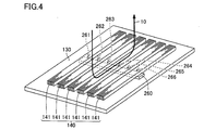
- FIG. 4 is a perspective view schematically showing a leakage magnetic flux that enters the magnetic shield of the stationary induction device according to the second embodiment of the present invention. 4 shows a state in which the magnetic shield is viewed from the same angle as in FIG. FIG. 4 shows an example of leakage magnetic flux.
- the first magnetic shield 140 of the stationary induction device As shown in FIG. 4, in the first magnetic shield 140 of the stationary induction device according to Embodiment 2 of the present invention, six metal magnetic bodies 141 are fixed to the inner wall of the tank 130 by one first stopper plate 260. ing. That is, three or more metal magnetic bodies 141 and the first stopper plate 260 are joined.
- the first stopper plate 260 is disposed at the approximate center of the metallic magnetic body 141 in the axial direction 1 of the winding 120.
- the first metal magnetic body 141 from the left side and the second metal magnetic body 141 from the left side are connected to each other only by the first stopper plate 260.
- the first metal magnetic body 141 and the first stopper plate 260 from the left are joined to each other at the joint 261.
- the second metal magnetic body 141 and the first stopper plate 260 from the left are joined to each other at the joint 262.
- the second metal magnetic body 141 from the left side and the third metal magnetic body 141 from the left side are connected to each other only by the first stopper plate 260.
- the third metal magnetic body 141 and the first stopper plate 260 from the left are joined to each other at the joint 263.
- the third metal magnetic body 141 from the left side and the fourth metal magnetic body 141 from the left side are connected to each other only by the first stopper plate 260.
- the fourth metal magnetic body 141 and the first stopper plate 260 from the left are joined to each other at the joint 264.
- the fourth metal magnetic body 141 from the left side and the fifth metal magnetic body 141 from the left side are connected to each other only by the first stopper plate 260.
- the fifth metal magnetic body 141 from the left side and the first stopper plate 260 are joined to each other at the joint portion 265.
- the fifth metal magnetic body 141 from the left side and the sixth metal magnetic body 141 from the left side are connected to each other only by the first stopper plate 260.
- the sixth metal magnetic body 141 from the left side and the first stopper plate 260 are joined to each other at the joint portion 266.
- an annular portion is formed by the metal magnetic bodies 141 adjacent to each other and the plurality of stop plates. Can be prevented.
- the first magnetic shield 140 when the first magnetic shield 140 is saturated by the leakage magnetic flux 10 generated from the winding 120 in the abnormal operation state and the leakage magnetic flux 10 penetrates the first magnetic shield 140, the first magnetic shield Since there is no annular portion serving as an eddy current path in 140, generation of eddy current flowing in the first magnetic shield 140 can be suppressed. As a result, local overheating due to eddy current flowing in the first magnetic shield 140 can be suppressed.
- the number of stop plates and the number of joints between the stop plate and the metal magnetic body can be reduced as compared with the static induction device 100 according to the first embodiment.
- the configuration of the static induction device can be simplified and the installation cost of the static induction device can be reduced.
- FIG. 5 is an inner side view showing the configuration of the magnetic shield of the stationary induction device according to the third embodiment of the present invention. In FIG. 5, the state which looked at the magnetic shield from the same direction as FIG. 2 is shown.
- the stationary guidance device includes a plurality of first stop plates.
- a part of the plurality of first stop plates is located on one end side of the metal magnetic body 141 in the axial direction 1 of the winding 120.
- the first stop plates 360x, 360b, 360d, and 360y are located on the upper end side of the metal magnetic body 141 in FIG.
- the first stop plates 360x, 360b, 360d, and 360y are arranged side by side on the same straight line, but are not limited to this, and may be located shifted from each other.
- the other part of the plurality of first stopper plates is located on the other end side of the metal magnetic body 141 in the axial direction 1 of the winding 120.
- the first stop plates 360a, 360c, and 360e are located on the lower end side of the metal magnetic body 141 in FIG.
- the first stopper plates 360a, 360c, and 360e are positioned side by side on the same straight line, but are not limited to this, and may be positioned shifted from each other.
- One of the plurality of metal magnetic bodies 141 is connected by a metal magnetic body 141 adjacent to one side in the direction 2 orthogonal to the axial direction 1 of the winding 120 and a first stopper plate located on one end side. And it is connected with the metal magnetic body 121 adjacent to the other side of the direction 2 orthogonal to the axial direction 1 of the coil
- the first metal magnetic body 141 from the left side and the second metal magnetic body 141 from the left side are connected to each other only by the first stopper plate 360a.
- the first metal magnetic body 141 and the first stopper plate 360a from the left are joined to each other at the joint 361a.
- the second metal magnetic body 141 from the left side and the first stopper plate 360a are joined to each other at the joint 362a.
- the first metal magnetic body 141 from the left side is joined to each other at the first stopper plate 360x and the joint portion 361x.
- the second metal magnetic body 141 from the left side and the third metal magnetic body 141 from the left side are connected to each other only by the first stopper plate 360b.
- the second metal magnetic body 141 from the left side and the first stopper plate 360b are joined to each other at the joint 362b.
- the third metal magnetic body 141 from the left side and the first stopper plate 360b are joined to each other at the joint 363b.
- the third metal magnetic body 141 from the left side and the fourth metal magnetic body 141 from the left side are connected to each other only by the first stopper plate 360c.
- the third metal magnetic body 141 from the left side and the first stopper plate 360c are joined to each other at the joint 363c.
- the fourth metal magnetic body 141 from the left side and the first stopper plate 360c are joined to each other at the joint 364c.
- the fourth metal magnetic body 141 from the left side and the fifth metal magnetic body 141 from the left side are connected to each other only by the first stopper plate 360d.
- the fourth metal magnetic body 141 from the left side and the first stopper plate 360d are joined to each other at the joint 364d.
- the fifth metal magnetic body 141 from the left side and the first stopper plate 360d are joined together at a joint portion 365d.
- the fifth metal magnetic body 141 from the left side and the sixth metal magnetic body 141 from the left side are connected to each other only by the first stopper plate 360e.
- the fifth metal magnetic body 141 from the left side and the first stopper plate 360e are joined to each other by a joint portion 365e.
- the sixth metal magnetic body 141 from the left side and the first stopper plate 360e are joined to each other by a joint portion 366e. Further, the sixth metal magnetic body 141 from the left side is joined to each other at the first stopper plate 360y and the joint portion 366y.
- an annular portion is formed by the metal magnetic bodies 141 adjacent to each other and the plurality of stop plates. Can be prevented.
- the first magnetic shield 140 when the first magnetic shield 140 is saturated by the leakage magnetic flux 10 generated from the winding 120 in the abnormal operation state and the leakage magnetic flux 10 penetrates the first magnetic shield 140, the first magnetic shield Since there is no annular portion serving as an eddy current path in 140, generation of eddy current flowing in the first magnetic shield 140 can be suppressed. As a result, local overheating due to eddy current flowing in the first magnetic shield 140 can be suppressed.
- each metal magnetic body 141 are fixed to the inner wall of the tank 130 by a stop plate. Therefore, compared with the case where only one end of each metal magnetic body 141 is fixed to the inner wall of the tank 130 by the stopper plate, the electromagnetic force generated from the energized winding 120 acts on each metal magnetic body 141. Thus, distortion of each metal magnetic body 141 generated can be reduced.
- the static induction device according to the present embodiment is different from the static induction device 100 according to the first embodiment only in that it further includes an insulator sandwiched between metal magnetic bodies. Therefore, description of other configurations will not be repeated. .
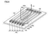
- FIG. 6 is a perspective view schematically showing a leakage magnetic flux that enters the magnetic shield of the stationary induction device according to the fourth embodiment of the present invention.
- FIG. 6 shows a state in which the magnetic shield is viewed from the same angle as in FIG.
- FIG. 6 shows an example of leakage magnetic flux.
- the stationary induction device further includes an insulator 180 sandwiched between metal magnetic bodies 141 adjacent to each other.
- the insulator 180 is disposed so as to be in contact with the side surfaces of both ends of the metal magnetic body 141.
- the arrangement of the insulator 180 is not limited to this, and for example, the metal magnetic body 141 You may arrange
- the insulator 180 only needs to have electrical insulation and resistance to insulating oil or insulating gas filled in the tank 130.
- insulating paper such as a press board, resin, It may be composed of rubber, wood or earthenware.
- the insulator 180 may be an insulating film formed by applying an insulating material to the side surface of the metal magnetic body 141.
- the insulator 180 By disposing the insulator 180, even when the metal magnetic body 141 is distorted by welding with the stopper plate, it is possible to prevent the metal magnetic bodies 141 adjacent to each other from coming into contact with each other. Moreover, it can suppress that the metal magnetic bodies 141 which mutually adjoin each other by the vibration generate
- FIG. 7 is a perspective view schematically showing a magnetic flux leaking into the magnetic shield of the stationary induction device according to the fifth embodiment of the present invention. 7 shows a state in which the magnetic shield is viewed from the same angle as in FIG. Moreover, in FIG. 7, an example of the leakage magnetic flux is shown.
- the stationary induction device further includes an insulator 190 sandwiched between metal magnetic bodies 141 adjacent to each other.
- the insulator 190 is sandwiched between the inner wall of the tank 130 and the metal magnetic body 141.
- the insulator 190 has a rectangular parallelepiped base portion 191 and two bent portions 192 that are bent from both ends of the base portion 191 so as to be orthogonal to the base portion 191.
- the insulator 190 is disposed so that the metal magnetic body 141 is accommodated in a space surrounded by the two bent portions 192 and the base portion 191.
- bent portions 192 of the insulators 190 adjacent to each other are sandwiched between the metal magnetic bodies 141 adjacent to each other and are in contact with each other.
- a base 191 of the insulator 190 is sandwiched between the inner wall of the tank 130 and the metal magnetic body 141.
- the insulator 190 only needs to be electrically insulating and resistant to insulating oil or insulating gas filled in the tank 130.
- insulating paper such as a press board, resin, It may be composed of rubber, wood or earthenware.
- the insulator 190 By disposing the insulator 190, it is possible to prevent the metal magnetic bodies 141 adjacent to each other from coming into contact with each other even when the metal magnetic body 141 is distorted by welding with the stopper plate. Moreover, it can suppress that the metal magnetic bodies 141 which mutually adjoin each other by the vibration generate
- the metal magnetic body 141 is distorted by welding with the stopper plate, it is possible to suppress the metal magnetic body 141 from being distorted so as to approach the inner wall of the tank 130. Further, it is possible to suppress contact between the metallic magnetic body 141 and the inner wall of the tank 130 due to vibration generated from the iron core 110 and the winding 120 that are energized.
- the static induction device according to the present embodiment is different from the static induction device according to the first embodiment only in that it further includes an insulator sandwiched between the inner wall of the tank and the metal magnetic body. Do not repeat.
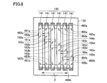
- FIG. 8 is an inner side view showing the configuration of the magnetic shield of the stationary induction device according to the sixth embodiment of the present invention. In FIG. 8, the state which looked at the magnetic shield from the same direction as FIG. 2 is shown.
- the stationary induction device further includes an insulator sandwiched between the inner wall of the tank 130 and the metal magnetic body 141.
- an insulator 480a and an insulator 480b are arranged.
- the number of insulators is not limited to two and may be one or more. Note that even if a plurality of insulators are arranged, a new eddy current path does not occur, and the effect of suppressing the distortion of the metal magnetic body 141 can be obtained by arranging a plurality of insulators. It is preferable to arrange an insulator.
- the insulator 480 a is located on one end side of the metal magnetic body 141 in the axial direction 1 of the winding 120. Specifically, the insulator 480a is located on the upper end side of the metal magnetic body 141 in FIG. The insulator 480 a extends in the direction 2 orthogonal to the axial direction 1 of the winding 120.
- the insulator 480 b is located on the other end side of the metal magnetic body 141 in the axial direction 1 of the winding 120. Specifically, the insulator 480b is located on the lower end side of the metal magnetic body 141 in FIG. The insulator 480 b extends in a direction 2 orthogonal to the axial direction 1 of the winding 120.
- the insulators 480a and 480b and the metal magnetic body 141 are bonded to each other by an adhesive, but may not be bonded. However, by joining the insulators 480 a and 480 b and the metal magnetic body 141, it is possible to suppress the metal magnetic body 141 from being distorted in the direction away from the inner wall of the tank 130.
- the first metal magnetic body 141 and the insulator 480a from the left are joined to each other at the joint 481a.
- the second metal magnetic body 141 and the insulator 480a from the left are joined to each other at the joint 482a.
- the third metal magnetic body 141 and the insulator 480a from the left are joined to each other at the joint 483a.
- the fourth metal magnetic body 141 from the left side and the insulator 480a are joined together at a joint 484a.
- the fifth metal magnetic body 141 and the insulator 480a from the left are joined to each other at a joint 485a.
- the sixth metal magnetic body 141 from the left side and the insulator 480a are joined together at a joint 486a.
- the first metal magnetic body 141 and the insulator 480b from the left are joined to each other at the joint 481b.
- the second metal magnetic body 141 and the insulator 480b from the left are joined to each other at the joint 482b.
- the third metal magnetic body 141 and the insulator 480b from the left are joined to each other at a joint 483b.
- the fourth metal magnetic body 141 and the insulator 480b from the left are joined to each other at the joint 484b.
- the fifth metal magnetic body 141 and the insulator 480b from the left are joined to each other at a joint 485b.
- the sixth metal magnetic body 141 and the insulator 480b from the left are joined to each other at a joint 486b.
- the insulator 480a and the insulator 480b are only required to have electrical insulation and resistance to insulating oil or insulating gas filled in the tank 130.
- insulation such as a press board is possible. You may be comprised from paper, resin, rubber
- the metal magnetic body 141 is distorted so as to approach the inner wall of the tank 130. Can be suppressed. Further, it is possible to suppress contact between the metallic magnetic body 141 and the inner wall of the tank 130 due to vibration generated from the iron core 110 and the winding 120 that are energized.
Landscapes
- Engineering & Computer Science (AREA)
- Power Engineering (AREA)
- Regulation Of General Use Transformers (AREA)
Abstract
Priority Applications (2)
| Application Number | Priority Date | Filing Date | Title |
|---|---|---|---|
| JP2015517023A JP6104373B2 (ja) | 2013-05-13 | 2014-04-30 | 静止誘導機器 |
| US14/765,651 US20150371769A1 (en) | 2013-05-13 | 2014-04-30 | Stationary induction device |
Applications Claiming Priority (2)
| Application Number | Priority Date | Filing Date | Title |
|---|---|---|---|
| JP2013-101022 | 2013-05-13 | ||
| JP2013101022 | 2013-05-13 |
Publications (1)
| Publication Number | Publication Date |
|---|---|
| WO2014185267A1 true WO2014185267A1 (fr) | 2014-11-20 |
Family
ID=51898247
Family Applications (1)
| Application Number | Title | Priority Date | Filing Date |
|---|---|---|---|
| PCT/JP2014/061948 Ceased WO2014185267A1 (fr) | 2013-05-13 | 2014-04-30 | Dispositif d'induction stationnaire |
Country Status (3)
| Country | Link |
|---|---|
| US (1) | US20150371769A1 (fr) |
| JP (1) | JP6104373B2 (fr) |
| WO (1) | WO2014185267A1 (fr) |
Cited By (1)
| Publication number | Priority date | Publication date | Assignee | Title |
|---|---|---|---|---|
| WO2017063669A1 (fr) * | 2015-10-13 | 2017-04-20 | Abb Schweiz Ag | Ensemble shunt magnétique pour blindage magnétique d'un dispositif d'alimentation |
Families Citing this family (2)
| Publication number | Priority date | Publication date | Assignee | Title |
|---|---|---|---|---|
| US12198850B2 (en) * | 2019-03-27 | 2025-01-14 | Mitsubishi Electric Corporation | Stationary induction apparatus |
| WO2022194328A2 (fr) * | 2021-03-19 | 2022-09-22 | REDUR GmbH & Co. KG | Corps de blindage basse tension, transformateur de courant basse tension, agencement de transformateur de courant basse tension ou ensemble électrique basse tension |
Citations (3)
| Publication number | Priority date | Publication date | Assignee | Title |
|---|---|---|---|---|
| JPS6310533U (fr) * | 1986-07-09 | 1988-01-23 | ||
| JP2000348953A (ja) * | 1999-06-04 | 2000-12-15 | Hitachi Ltd | 静止誘導電器の磁気遮蔽装置 |
| JP2012222332A (ja) * | 2011-04-14 | 2012-11-12 | Mitsubishi Electric Corp | 静止誘導機器 |
Family Cites Families (10)
| Publication number | Priority date | Publication date | Assignee | Title |
|---|---|---|---|---|
| JPH0744117B2 (ja) * | 1985-11-01 | 1995-05-15 | 株式会社日立製作所 | 静止誘導電器用磁気シ−ルド |
| JPH06112059A (ja) * | 1992-09-29 | 1994-04-22 | Toshiba Corp | 静止誘導電器 |
| JPH07211558A (ja) * | 1994-01-20 | 1995-08-11 | Hitachi Ltd | 静止誘導電器の磁気シールド |
| JPH0851037A (ja) * | 1994-08-05 | 1996-02-20 | Toshiba Corp | 静止誘導電器 |
| JPH08124767A (ja) * | 1994-10-25 | 1996-05-17 | Toshiba Corp | 静止誘導電器 |
| JPH10116741A (ja) * | 1996-10-14 | 1998-05-06 | Toshiba Corp | 静止誘導電器の磁気シールド及びその取付方法 |
| JPH11340057A (ja) * | 1998-05-26 | 1999-12-10 | Hitachi Ltd | 静止誘導電気機器 |
| JP2001244128A (ja) * | 2000-02-25 | 2001-09-07 | Hitachi Ltd | 静止誘導電器 |
| JP4458542B2 (ja) * | 2005-12-28 | 2010-04-28 | 鹿島建設株式会社 | 磁気シールド用ブレード材及び磁気シールド簾体 |
| JP2011035159A (ja) * | 2009-07-31 | 2011-02-17 | Tokyo Electric Power Co Inc:The | 静止誘導電器 |
-
2014
- 2014-04-30 US US14/765,651 patent/US20150371769A1/en not_active Abandoned
- 2014-04-30 JP JP2015517023A patent/JP6104373B2/ja not_active Expired - Fee Related
- 2014-04-30 WO PCT/JP2014/061948 patent/WO2014185267A1/fr not_active Ceased
Patent Citations (3)
| Publication number | Priority date | Publication date | Assignee | Title |
|---|---|---|---|---|
| JPS6310533U (fr) * | 1986-07-09 | 1988-01-23 | ||
| JP2000348953A (ja) * | 1999-06-04 | 2000-12-15 | Hitachi Ltd | 静止誘導電器の磁気遮蔽装置 |
| JP2012222332A (ja) * | 2011-04-14 | 2012-11-12 | Mitsubishi Electric Corp | 静止誘導機器 |
Cited By (2)
| Publication number | Priority date | Publication date | Assignee | Title |
|---|---|---|---|---|
| WO2017063669A1 (fr) * | 2015-10-13 | 2017-04-20 | Abb Schweiz Ag | Ensemble shunt magnétique pour blindage magnétique d'un dispositif d'alimentation |
| US10796845B2 (en) | 2015-10-13 | 2020-10-06 | Abb Power Grids Switzerland Ag | Magnetic shunt assembly for magnetic shielding of a power device |
Also Published As
| Publication number | Publication date |
|---|---|
| JPWO2014185267A1 (ja) | 2017-02-23 |
| US20150371769A1 (en) | 2015-12-24 |
| JP6104373B2 (ja) | 2017-03-29 |
Similar Documents
| Publication | Publication Date | Title |
|---|---|---|
| JP2010129692A (ja) | インダクタンス部品 | |
| JP6104373B2 (ja) | 静止誘導機器 | |
| US9601255B2 (en) | Amorphous core transformer | |
| JP5842282B2 (ja) | コイル部品 | |
| JP4287495B1 (ja) | 三相高周波トランス | |
| JP2012023090A (ja) | リアクトル | |
| US8508323B2 (en) | Transformer | |
| US8547193B2 (en) | Stationary induction apparatus | |
| JP6594531B2 (ja) | 変流器モジュール | |
| WO2016092612A1 (fr) | Dispositif d'induction fixe | |
| JP6572541B2 (ja) | 変圧器 | |
| JP2015228470A (ja) | コイル部品 | |
| JP2009105180A (ja) | トランス | |
| JP5177231B2 (ja) | アーク溶接機に用いる変圧器およびアーク溶接機に用いる変圧器の組み立て方法 | |
| JP2012222332A (ja) | 静止誘導機器 | |
| JP5815116B2 (ja) | 静止誘導機器 | |
| JP2012230957A (ja) | 静止誘導機器 | |
| JP4892883B2 (ja) | 電力変換トランス | |
| JP5911441B2 (ja) | Dc−dcコンバータのトランス配線構造 | |
| JP6692502B1 (ja) | 静止誘導機器 | |
| JP2018113325A (ja) | 静止誘導器 | |
| JPWO2017002225A1 (ja) | 変圧器 | |
| JP2012004345A (ja) | 静止誘導機器およびその製造方法 | |
| JP2009246080A (ja) | 静止誘導電器 | |
| JP7413299B2 (ja) | 静止誘導電器および静止誘導電器の製造方法 |
Legal Events
| Date | Code | Title | Description |
|---|---|---|---|
| 121 | Ep: the epo has been informed by wipo that ep was designated in this application |
Ref document number: 14797344 Country of ref document: EP Kind code of ref document: A1 |
|
| ENP | Entry into the national phase |
Ref document number: 2015517023 Country of ref document: JP Kind code of ref document: A |
|
| WWE | Wipo information: entry into national phase |
Ref document number: 14765651 Country of ref document: US |
|
| NENP | Non-entry into the national phase |
Ref country code: DE |
|
| 122 | Ep: pct application non-entry in european phase |
Ref document number: 14797344 Country of ref document: EP Kind code of ref document: A1 |