WO2014188466A1 - Stator et moteur électrique le mettant en œuvre - Google Patents
Stator et moteur électrique le mettant en œuvre Download PDFInfo
- Publication number
- WO2014188466A1 WO2014188466A1 PCT/JP2013/003180 JP2013003180W WO2014188466A1 WO 2014188466 A1 WO2014188466 A1 WO 2014188466A1 JP 2013003180 W JP2013003180 W JP 2013003180W WO 2014188466 A1 WO2014188466 A1 WO 2014188466A1
- Authority
- WO
- WIPO (PCT)
- Prior art keywords
- electrical resistivity
- wire
- ratio
- cross
- winding
- Prior art date
- Legal status (The legal status is an assumption and is not a legal conclusion. Google has not performed a legal analysis and makes no representation as to the accuracy of the status listed.)
- Ceased
Links
Images



Classifications
-
- H—ELECTRICITY
- H02—GENERATION; CONVERSION OR DISTRIBUTION OF ELECTRIC POWER
- H02K—DYNAMO-ELECTRIC MACHINES
- H02K3/00—Details of windings
- H02K3/04—Windings characterised by the conductor shape, form or construction, e.g. with bar conductors
- H02K3/18—Windings for salient poles
-
- H—ELECTRICITY
- H02—GENERATION; CONVERSION OR DISTRIBUTION OF ELECTRIC POWER
- H02K—DYNAMO-ELECTRIC MACHINES
- H02K3/00—Details of windings
- H02K3/02—Windings characterised by the conductor material
Definitions
- the present invention relates to an electric motor and a stator used for the electric motor.
- the stator core is made of laminated steel plates.
- An insulator is incorporated in the stator core.
- the insulator is a synthetic resin insulator.
- the annular stator core is integrally formed with teeth that protrude radially inward at a plurality of locations that equally divide the inner circumference in the circumferential direction.
- a wire rod is wound around each tooth portion via an insulator to form a multi-layered winding portion.
- the innermost one layer is an aluminum wire, and the remaining five outer layers are copper wires (see Patent Document 1).
- an insulator is placed in the stator slots of the stator core.
- the main winding is housed inside this insulator.
- the main winding is formed by winding the main magnet wire into a random winding.
- the number of magnet wires is, for example, 34.
- the auxiliary winding is accommodated in a space formed between adjacent main windings.
- the auxiliary winding is formed by winding the same number of auxiliary magnet wires as the main winding.
- the diameter of the auxiliary magnet wire is 154/1000 of the main magnet wire.
- JP 2010-183788 (for example, paragraphs 0028, 0030, 0032, and FIG. 1)
- Patent Document 1 and Patent Document 2 describe a technique of using a copper wire and an aluminum wire for the stator winding. However, Patent Document 1 and Patent Document 2 do not disclose a configuration for reducing the resistance of the winding when materials having different electrical resistivity are used for the winding.
- An object of the present invention is to provide a configuration capable of reducing the resistance of a winding when materials having different electrical resistivity are used for the winding.
- a stator according to the present invention is disposed in a cylindrical stator core, a plurality of teeth provided along the circumferential direction of the stator core, and a plurality of slots provided between the teeth, and wound around the teeth.
- the winding is (1) Consists of materials with different electrical resistivity, (2) The ratio of the cross-sectional area of the material having a high electrical resistivity to the cross-sectional area of the material having a low electrical resistivity in the slot is 1 or more, (3) It is below the ratio of the electrical resistivity of the material with high electrical resistivity to the electrical resistivity of the material with low electrical resistivity.
- the resistance of the winding can be reduced when materials having different electrical resistivity are used for the winding.
- FIG. 3 is a partial cross-sectional view of the stator according to Embodiment 1 of the present invention. It is sectional drawing of a part of stator in Embodiment 2 of this invention.
- FIG. 6 is a partial cross-sectional view of a stator according to Embodiment 3 of the present invention.
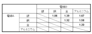
- FIG. 10 is a partial cross-sectional view of a stator according to Embodiment 4 of the present invention. It is sectional drawing of a part of stator in Embodiment 5 of this invention. It is a list of the ratio of the combination of the material of the electric wire which concerns on Embodiment 1 thru
- Embodiment 1 The structure of the electric motor according to Embodiment 1 of the present invention will be described with reference to FIG.
- FIG. 1 is a diagram illustrating the structure of the electric motor according to the first embodiment.
- the electric motor includes a rotor (in the following description, a rotor) that rotates, and a stator (in the following description, a stator 1 that generates a rotational force). ).
- a shaft is fixed to the rotor at the center in the radial direction.
- the rotor is configured by arranging a plurality of permanent magnets.
- the stator 1 has a cylindrical shape and covers the rotor from the outside in the radial direction.
- the stator 1 is configured by arranging a plurality of coils in the circumferential direction around a shaft.
- the AC power supply supplies an AC current to the coil of the stator 1.
- a load is connected to the shaft.
- the coil of the stator 1 generates a magnetic flux ⁇ as shown in FIG. 1 when a current flows.
- the permanent magnet of the rotor receives a magnetic force in the direction of the magnetic flux ⁇ .
- the rotor is driven by the magnetic force received by the permanent magnet.
- the direction of the magnetic field generated by the coil is successively moved in the circumferential direction.
- This can be realized by supplying an alternating current to a plurality of coils of the stator 1.
- the plurality of coils of the stator 1 generate a clockwise or counterclockwise magnetic field (referred to as a rotating magnetic field in the following description).
- the plurality of coils generate a clockwise rotating magnetic field.
- the permanent magnet receives a magnetic force in the rotating direction of the rotating magnetic field.
- the rotor rotates in the same direction as the rotating magnetic field.
- the shaft rotates with the rotor.
- the rotational force of the shaft is transmitted to the load. That is, the rotational force generated in the rotor is transmitted to the load through the shaft.
- FIG. 2 is a cross-sectional view of the stator 1 according to the first embodiment.
- the stator 1 mainly includes a cylindrical stator core 2 and a tooth portion 3.
- the teeth part 3 is provided in the inner periphery of the stator core 2 as shown in FIG.
- twelve teeth portions 3 are provided in the stator 1 along the circumferential direction shown in FIG.
- Slots 4 are provided between the tooth portions 3.
- the slot 4 is a space portion between the tooth portions 3.
- twelve slots 4 are provided in the stator 1 along the circumferential direction shown in FIG.
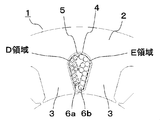
- FIG. 3 is a partial cross-sectional view of the stator 1 according to the first embodiment of the present invention, and is an enlarged view of a portion C in FIG.
- the stator core 2 is provided with a tooth portion 3.
- Slots 4 are provided between the tooth portions 3.
- the insulating paper 5 is provided inside the slot 4 along the shape of the slot 4.
- the copper wire 6a and the aluminum wire 6b are provided in the same slot 4.
- the copper wire 6 a and the aluminum wire 6 b are wound around the tooth portion 3 of the stator core 2.
- the copper wire 6a and the aluminum wire 6b are combined to form a winding 6.
- the resistance of the winding 6 is defined as a winding resistance R.
- the winding resistance R is expressed by the following formula 1.
- ⁇ A and ⁇ B are electrical resistivity of the electric wires A and B.
- n A and n B are the number of turns of the electric wires A and B, respectively.
- L is the average circumference.
- S A and S B are cross-sectional areas of the electric wires A and B, respectively.
- a is a constant determined by the number of slots and the method of connecting the windings 6.
- ⁇ is a space factor.
- the space factor is the ratio of the area of the windings 6 to the area A S of the slot 4 are occupied.
- N is the total number of turns of the electric wire A and the electric wire B.
- the ratio of the electric wire A is x.
- the cross-sectional area S B of the wire B, and y-fold cross-sectional area S A of the wire A is derived from the expression 2.
- winding resistance R (x, y) is expressed by Equation 4 below.
- 1 ⁇ y ⁇ B / ⁇ A is a mathematical expression that leads to the following two points.
- the first point is that the ratio of the cross-sectional area of the material having a high electrical resistivity to the cross-sectional area of the material having a low electrical resistivity in the slot 4 is 1 or more.
- a second point is a configuration in which the ratio is equal to or less than a ratio of the electrical resistivity of the material having a high electrical resistivity to the electrical resistivity of the material having the low electrical resistivity.
- the configuration of the stator 1 according to the first embodiment will be described in detail.
- the copper wire 6a is used as the electric wire A and the aluminum wire 6b is used as the electric wire B as shown in FIG.
- the winding method of the copper wire 6a and the aluminum wire 6b is concentrated winding.
- a region D represents a region occupied by the copper wire 6 a in the slot 4. That is, the region D is the sum of the cross-sectional areas of the copper wires 6 a in the slot 4.
- a region E represents a region occupied by the aluminum wire 6 b in the slot 4. That is, the region E is the sum of the cross-sectional areas of the aluminum wires 6 b in the slot 4.
- the ratio of the area of the area E occupied by the aluminum wire 6b to the area of the area including the area D and the area E is in a range larger than 50% and smaller than 61%.
- the electrical resistivity ⁇ A of copper is 16.8 n ⁇ ⁇ m.
- the electrical resistivity ⁇ B of aluminum is 26.5 n ⁇ ⁇ m.
- the cross-sectional area of the copper wire 6a to S copper, the cross-sectional area of the aluminum wire 6b and S A is 16.8 n ⁇ ⁇ m.
- Equation 9 is derived.
- the ratio of the occupied area of the aluminum wire 6b in the slot 4 to the occupied area of the winding 6 in the slot 4 is set in a range larger than 50% and smaller than 61%.
- the occupied area is the product of the cross-sectional area and the number of turns of the electric wire.
- the ratio of the area of the region E occupied by the aluminum wire 6b to the area of the region D and the region E is set to a range larger than 50% and smaller than 61%.
- the occupation area of the copper wire 6a and the occupation area of the aluminum wire 6b may be the same. Further, the ratio of the occupied area of the aluminum wire 6b in the slot 4 to the occupied area of the winding 6 in the slot 4 may be 61%.
- Embodiment 2 Next, the configuration of the stator 1 and the electric motor according to the second embodiment will be described. The same or equivalent means and configuration as in the first embodiment will be described using the same names and symbols.
- the ratio of the cross-sectional area of the material having a high electrical resistivity to the cross-sectional area of the material having a low electrical resistivity in the slot is equal to the ratio of the material having a high electrical resistivity to the electrical resistivity of the material having a low electrical resistivity.
- a stator that is equivalent to the square root of the ratio of electrical resistivity will be particularly described.
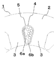
- FIG. 4 is a cross-sectional view of a part of the stator 1 according to Embodiment 2 of the present invention.
- FIG. 4 is an enlarged view of part C in FIG.
- the copper wire 6 a and the aluminum wire 6 b are provided in the same slot 4.
- the copper wire 6 a and the aluminum wire 6 b are wound around the tooth portion 3 of the stator core 2.
- the winding method of the copper wire 6a and the aluminum wire 6b is concentrated winding.
- the winding 6 arranged in the same slot 4 has 20 turns.
- the winding 6 provided in the same slot 4 occupies 55% of the area of the slot 4.
- the number of turns of the copper wire 6a and the aluminum wire 6b is 10 turns.
- the wire diameter of the copper wire 6a is 0.45 mm.
- the wire diameter of the aluminum wire 6b is 0.55 mm.
- Equation 12 is derived.
- the copper wire 6a is used as the electric wire A and the aluminum wire 6b is used as the electric wire B, respectively, as shown in FIG.
- the ratio of the cross-sectional area of the copper wire 6a and the aluminum wire 6b to the cross-sectional area of the slot 4 is 1.26 times. This is the same as the square root of the ratio of copper electrical resistivity 16.8 n ⁇ ⁇ m and aluminum electrical resistivity 26.5 n ⁇ ⁇ m.
- the number of turns of the copper wire 6a and the aluminum wire 6b is 10 turns.
- the wire diameter of the copper wire 6a is 0.45 mm.
- the wire diameter of the aluminum wire 6b is 0.55 mm. This satisfies 1.26 times the ratio of the cross-sectional area. That is, in this case, the winding resistance can be minimized.
- the diameter of the electric wire that is generally distributed takes a discrete value.
- the winding number is a natural number. For this reason, it is usually difficult to make the ratio of the cross-sectional area of the copper wire 6a and the aluminum wire 6b equal to the square root of the ratio of electrical resistivity. Therefore, the diameter of the electric wire is selected so that the ratio of the cross-sectional area is 1.3 times instead of 1.26 times. Thereby, winding resistance can be made the smallest.
- the diameter of the electric wire may be selected so that the ratio of the cross-sectional area is in the range of 1.2 to 1.4 times.
- the ratio of the cross-sectional area when the winding resistance can be minimized is included in the range of 1.2 times to 1.4 times. For this reason, the winding resistance can be minimized by selecting the diameter of the electric wire so as to be in the range of 1.2 times to 1.4 times. In addition, it is said that it is in the range which can be considered that the ratio of said cross-sectional area exists in the range of this 1.2 times-1.4 times.
- Embodiment 3 Next, the configuration of the stator 1 and the electric motor according to Embodiment 3 will be described. With respect to the same or equivalent means and configuration as in the first and second embodiments, the same names and reference numerals are used and the description thereof is omitted.
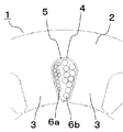
- FIG. 5 is a cross-sectional view of a part of the stator 1 according to Embodiment 3 of the present invention.
- FIG. 5 is an enlarged view of part C in FIG.
- the copper wire 6 a and the aluminum wire 6 b are provided in the same slot 4.
- the copper wire 6 a and the aluminum wire 6 b are wound around the tooth portion 3 of the stator core 2.
- the winding method of the copper wire 6a and the aluminum wire 6b is concentrated winding.
- the winding 6 provided in the same slot 4 has 20 turns.
- the winding 6 provided in the same slot 4 occupies 55% of the area of the slot 4.
- the winding number of the copper wire 6a is 8 turns.
- the winding number of the aluminum wire 6b is 12 turns.
- the diameter of the copper wire 6a is 0.4 mm.
- the wire diameter of the aluminum wire 6b is 0.55 mm.
- the ratio of the cross-sectional area of the copper wire 6a and the aluminum wire 6b to the cross-sectional area of the slot 4 is 1.26 times. In this case, the winding resistance can be minimized as described in the second embodiment.
- the winding resistance can be minimized by adopting a configuration in which the ratio of the cross-sectional area is 1.26 times.
- the diameter of the electric wire that is generally distributed takes a discrete value.
- the winding number is a natural number. For this reason, it is usually difficult to make the ratio of the cross-sectional area of the copper wire 6a and the aluminum wire 6b equal to the square root of the ratio of electrical resistivity. Therefore, the diameter of the electric wire is selected so that the ratio of the cross-sectional area is 1.3 times instead of 1.26 times. Thereby, winding resistance can be made the smallest.
- the diameter of the electric wire may be selected so that the ratio of the cross-sectional area is in the range of 1.2 to 1.4 times.
- the ratio of the cross-sectional area when the winding resistance can be minimized is included in the range of 1.2 times to 1.4 times. For this reason, the winding resistance can be minimized by selecting the diameter of the electric wire so as to be in the range of 1.2 times to 1.4 times. In addition, it is said that it is in the range which can be considered that the ratio of said cross-sectional area exists in the range of this 1.2 times-1.4 times.
- Embodiment 4 Next, the configuration of the stator 1 and the electric motor according to Embodiment 4 will be described. The same or equivalent means and configuration as in the first to third embodiments will be described using the same names and reference numerals.
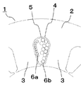
- FIG. 6 is a partial cross-sectional view of the stator 1 according to the fourth embodiment of the present invention.
- FIG. 6 is an enlarged view of part C in FIG.
- the copper wire 6 a and the aluminum wire 6 b are arranged in the same slot 4.
- the copper wire 6 a and the aluminum wire 6 b are wound around the tooth portion 3 of the stator core 2.
- the winding method of the copper wire 6a and the aluminum wire 6b is concentrated winding.
- the winding 6 provided in the same slot 4 has 20 turns. Further, the windings 6 arranged in the same slot 4 occupy 55% of the area of the slot 4.
- the number of turns of the copper wire 6a and the aluminum wire 6b is 10 turns.
- the wire diameter of the copper wire 6a is 0.4 mm, and the wire diameter of the aluminum wire 6b is 0.6 mm.
- the specific gravity of the electric wires A and B described in the first embodiment is ⁇ A and ⁇ B.
- the weight m of the winding 6 is expressed by the following Expression 14.
- a copper wire 6 a is used as the electric wire A
- an aluminum wire 6 b is used as the electric wire B.
- the ratio of the cross-sectional area of the copper wire 6a and the aluminum wire 6b to the cross-sectional area of the slot 4 is 1.58 times. This is the same as the ratio of the electrical resistivity of copper 16.8 n ⁇ ⁇ m and the electrical resistivity of aluminum 26.5 n ⁇ ⁇ m.
- the number of turns of the copper wire 6a and the aluminum wire 6b is 10 turns.
- the wire diameter of the copper 6a is 0.4 mm.
- the wire diameter of the aluminum wire 6b is 0.6 mm. This satisfies 1.58 times the ratio of the cross-sectional area. That is, in this case, compared with the case where the cross-sectional areas of the copper wire 6a and the aluminum wire 6b are the same, the winding resistance can be made equal and the weight of the winding 6 can be made lightest.
- the diameter of the electric wire that is generally distributed takes a discrete value.
- the winding number is a natural number. For this reason, it is usually difficult to make the ratio of the cross-sectional area of the copper wire 6a and the aluminum wire 6b equal to the ratio of electrical resistivity. Therefore, the diameter of the electric wire is selected so that the ratio of the cross-sectional area is 1.6 times instead of 1.58 times. Thereby, compared with the case where the cross-sectional area of the copper wire 6a and the aluminum wire 6b is made the same, winding resistance can be made equivalent and the weight of the winding 6 can be made the lightest.
- the diameter of the electric wire may be selected so that the ratio of the cross-sectional area is in a range of 1.5 times to 1.7 times. Compared with the case where the cross-sectional areas of the copper wire 6a and the aluminum wire 6b are the same, the ratio of the cross-sectional area when the winding resistance is the same and the weight of the winding 6 can be minimized is 1.5. It is included in the range of double to 1.7 times. For this reason, by selecting the diameter of the electric wire so as to be in the range of 1.5 times to 1.7 times, the winding resistance can be reduced as compared with the case where the cross-sectional areas of the copper wire 6a and the aluminum wire 6b are the same. The weight of the winding 6 can be made lightest. In addition, it is said that it is in the range which can be considered that the ratio of said cross-sectional area exists in the range of 1.5 times-1.7 times this is equivalent.
- Embodiment 5 Next, the configuration of the stator 1 and the electric motor according to the fifth embodiment will be described. The same or equivalent means and configuration as those in the first to fourth embodiments will be described using the same names and symbols.
- FIG. 7 is a partial cross-sectional view of stator 1 according to the fifth embodiment of the present invention.
- FIG. 7 is an enlarged view of part C in FIG.
- the copper wire 6 a and the aluminum wire 6 b are arranged in the same slot 4.
- the copper wire 6 a and the aluminum wire 6 b are wound around the tooth portion 3 of the stator core 2.
- the winding method of the copper wire 6a and the aluminum wire 6b is concentrated winding.
- the winding 6 arranged in the same slot 4 has 20 turns. Further, the windings 6 arranged in the same slot 4 occupy 55% of the area of the slot 4.
- the number of turns of the copper wire 6a is 8 turns.
- the winding number of the aluminum wire 6b is 12 turns.
- the wire diameter of the copper wire 6a is 0.35 mm.
- the wire diameter of the aluminum wire 6b is 0.55 mm.
- the ratio of the cross-sectional area of the copper wire 6a and the aluminum wire 6b to the cross-sectional area of the slot 4 is 1.58 times.
- the winding resistance can be made equal and the weight of the winding 6 can be minimized. it can.
- the cross-sectional area of the copper wire 6a and the aluminum wire 6b can be reduced by configuring the cross-sectional area ratio to be 1.58 times. Compared to the case where they are the same, the winding resistance can be made equal, and the weight of the winding 6 can be minimized.
- the diameter of the electric wire may be selected so that the ratio of the cross-sectional area is in a range of 1.5 times to 1.7 times. Compared with the case where the cross-sectional areas of the copper wire 6a and the aluminum wire 6b are the same, the ratio of the cross-sectional area when the winding resistance is the same and the weight of the winding 6 can be minimized is 1.5. It is included in the range of double to 1.7 times. For this reason, by selecting the diameter of the electric wire so as to be in the range of 1.5 times to 1.7 times, the winding resistance can be reduced as compared with the case where the cross-sectional areas of the copper wire 6a and the aluminum wire 6b are the same. The weight of the winding 6 can be made lightest. In addition, it is said that it is in the range which can be considered that the ratio of said cross-sectional area exists in the range of 1.5 times-1.7 times this is equivalent.
- the diameter of the electric wire that is generally distributed takes a discrete value.
- the winding number is a natural number. For this reason, it is usually difficult to make the ratio of the cross-sectional area of the copper wire 6a and the aluminum wire 6b equal to the ratio of electrical resistivity. Therefore, the diameter of the electric wire is selected so that the ratio of the cross-sectional area is 1.6 times instead of 1.58 times. Thereby, compared with the case where the cross-sectional area of the copper wire 6a and the aluminum wire 6b is made the same, winding resistance can be made equivalent and the weight of the winding 6 can be made the lightest.
- or Embodiment 5 although the winding method of the copper wire 6a and the aluminum wire 6b was concentrated winding, it is not restricted to this.
- the winding method of the copper wire 6a and the aluminum wire 6b may be distributed winding.
- the stator 1 has twelve teeth 3 and twelve slots 4.
- the present invention is not limited to this.
- the number of teeth portions 3 and slots 4 may be various configurations such as 3, 6, 9, or more.
- a copper wire 6a is used as the electric wire A, and an aluminum wire 6b is used as the electric wire B.
- the copper wire 6a has a low electrical resistivity and a small energy loss.
- the aluminum wire 6b is lighter and cheaper than the copper wire 6a. That is, in Embodiments 1 to 5, by using the copper wire 6a and the aluminum wire 6b, the stator 1 can be reduced in weight and cost can be reduced.
- the copper wire 6a is used as the electric wire A and the aluminum wire 6b is used as the electric wire B.
- the present invention is not limited to this.
- money, aluminum etc. can be selected and used.
- FIG. 8 is a list of the ratios of the combinations of electric wire materials and the electrical resistivity according to the first to fifth embodiments of the present invention.
- the ratio of the electrical resistivity is the ratio of the electrical resistivity of the metal having a large electrical resistivity to the electrical resistivity of the metal having a small electrical resistivity.
- the electrical resistivity of each material is 15.9 n ⁇ m for silver, 16.8 n ⁇ m for copper, 22.1 n ⁇ m for gold, and 26.5 n ⁇ m for aluminum at 20 ° C.
- the electric wires A in the column are metals having a low electric resistivity
- the electric wires B in the row are metals having a high electric resistivity.
- the numerical values in FIG. 8 indicate the ratio ⁇ B / ⁇ A of the electrical resistivity of the electric wires A and B.
- the ratio of the electrical resistivity of aluminum as the electric wire B to copper as the electric wire A is 1.58 at 20 ° C.
- the values in FIG. 8 are all values at 20 ° C., and the values change as the temperature changes.
- the material of the electric wires according to the first to fifth embodiments two kinds of different metals are selected from silver, copper, gold, and aluminum. That is, as the material for the electric wire A, one is selected from silver, copper, and gold, and as the material for the electric wire B, a material having a higher electrical resistivity than the electric wire A is selected. Specifically, when silver is selected for the electric wire A, the electric wire B is selected from copper, gold, and aluminum. When copper is selected as the electric wire A, the electric wire B is selected from gold and aluminum. When gold is selected for the electric wire A, the electric wire B is aluminum. Even if a combination of these materials is selected as the material of the electric wires A and B, it is clear that the effects obtained in the stator 1 and the electric motor according to the first to fifth embodiments are not hindered.
- stator 1 stator, 2 stator core, 3 teeth, 4 slots, 5 insulation paper, 6a copper wire, 6b aluminum wire
Landscapes
- Engineering & Computer Science (AREA)
- Power Engineering (AREA)
- Windings For Motors And Generators (AREA)
Abstract
Priority Applications (7)
| Application Number | Priority Date | Filing Date | Title |
|---|---|---|---|
| JP2014506668A JP5708880B1 (ja) | 2013-05-20 | 2013-05-20 | 固定子及びこの固定子を使用する電動機 |
| DE112013007001.4T DE112013007001B4 (de) | 2013-05-20 | 2013-05-20 | Stator mit Wicklungen aus Materialien mit unterschiedlichen spezifischen elektrischen Widerständen |
| KR1020157032160A KR101642243B1 (ko) | 2013-05-20 | 2013-05-20 | 고정자 및 이 고정자를 사용하는 전동기 |
| US14/890,089 US9413200B2 (en) | 2013-05-20 | 2013-05-20 | Stator and electric motor using same |
| CN201380076718.2A CN105229899B (zh) | 2013-05-20 | 2013-05-20 | 固定件以及使用该固定件的电动机 |
| PCT/JP2013/003180 WO2014188466A1 (fr) | 2013-05-20 | 2013-05-20 | Stator et moteur électrique le mettant en œuvre |
| TW102121875A TWI515999B (zh) | 2013-05-20 | 2013-06-20 | 定子及使用該定子之電動機 |
Applications Claiming Priority (1)
| Application Number | Priority Date | Filing Date | Title |
|---|---|---|---|
| PCT/JP2013/003180 WO2014188466A1 (fr) | 2013-05-20 | 2013-05-20 | Stator et moteur électrique le mettant en œuvre |
Publications (1)
| Publication Number | Publication Date |
|---|---|
| WO2014188466A1 true WO2014188466A1 (fr) | 2014-11-27 |
Family
ID=51933061
Family Applications (1)
| Application Number | Title | Priority Date | Filing Date |
|---|---|---|---|
| PCT/JP2013/003180 Ceased WO2014188466A1 (fr) | 2013-05-20 | 2013-05-20 | Stator et moteur électrique le mettant en œuvre |
Country Status (7)
| Country | Link |
|---|---|
| US (1) | US9413200B2 (fr) |
| JP (1) | JP5708880B1 (fr) |
| KR (1) | KR101642243B1 (fr) |
| CN (1) | CN105229899B (fr) |
| DE (1) | DE112013007001B4 (fr) |
| TW (1) | TWI515999B (fr) |
| WO (1) | WO2014188466A1 (fr) |
Cited By (6)
| Publication number | Priority date | Publication date | Assignee | Title |
|---|---|---|---|---|
| AT14389U1 (de) * | 2014-04-22 | 2015-10-15 | Secop Austria Gmbh | Wicklung eines Elektromotors |
| CN108141085A (zh) * | 2015-09-11 | 2018-06-08 | 法雷奥电机设备公司 | 具有改进的磁性能的旋转电机的定子 |
| WO2019163021A1 (fr) * | 2018-02-21 | 2019-08-29 | 三菱電機株式会社 | Stator, moteur électrique, compresseur et dispositif de climatisation |
| WO2019220610A1 (fr) * | 2018-05-18 | 2019-11-21 | 三菱電機株式会社 | Stator, moteur, compresseur et dispositif de climatisation |
| US11831212B2 (en) | 2018-06-01 | 2023-11-28 | Mitsubishi Electric Corporation | Stator, electric motor, compressor, and air conditioner |
| WO2024009350A1 (fr) * | 2022-07-04 | 2024-01-11 | 三菱電機株式会社 | Stator, moteur électrique, compresseur, dispositif à cycle de réfrigération, et procédé de production de stator |
Families Citing this family (12)
| Publication number | Priority date | Publication date | Assignee | Title |
|---|---|---|---|---|
| DE102016114569A1 (de) * | 2016-08-05 | 2018-02-08 | Volabo Gmbh | Elektrische Maschine |
| TWI622249B (zh) * | 2016-11-25 | 2018-04-21 | 台達電子工業股份有限公司 | 定子 |
| DE102018208686A1 (de) * | 2018-06-01 | 2019-12-05 | Siemens Aktiengesellschaft | Elektrische Maschine und hybrid-elektrisches Luftfahrzeug |
| US20200235621A1 (en) * | 2019-01-17 | 2020-07-23 | Borgwarner Inc. | Stator assembly with both copper conductors and aluminum conductors disposed in same slot for phase winding |
| EP3696949B1 (fr) | 2019-02-12 | 2023-08-16 | Goodrich Actuation Systems Limited | Moteur comportant une résistance de freinage par récupération |
| EP3977605B1 (fr) * | 2019-05-28 | 2023-04-26 | B&R Industrial Automation GmbH | Dispositif de transport |
| CN113872401B (zh) * | 2020-06-30 | 2022-12-27 | 北京金风科创风电设备有限公司 | 电机的线圈及其制作方法、电机定子及其制作方法、电机 |
| DE102020121380A1 (de) | 2020-08-14 | 2022-02-17 | Dr. Ing. H.C. F. Porsche Aktiengesellschaft | Stator für eine elektrische Maschine, Verfahren zu seiner Herstellung, elektrische Maschine und Kraftfahrzeug |
| US20230378838A1 (en) * | 2020-12-22 | 2023-11-23 | Aisin Corporation | Stator |
| JP7170345B1 (ja) * | 2021-05-13 | 2022-11-14 | 株式会社アスター | コイル、ステータ、モータおよびコイルの製造方法 |
| DE102021119414A1 (de) * | 2021-07-27 | 2023-02-02 | Additive | Drives GmbH | Verfahren zur Herstellung eines Stators |
| TWI900182B (zh) * | 2024-08-16 | 2025-10-01 | 大陸商深圳興奇宏科技有限公司 | 馬達定子結構 |
Citations (5)
| Publication number | Priority date | Publication date | Assignee | Title |
|---|---|---|---|---|
| JPH10174330A (ja) * | 1996-12-17 | 1998-06-26 | Toshiba Corp | 三相電機子巻線 |
| JP2004153874A (ja) * | 2002-10-28 | 2004-05-27 | Nissan Motor Co Ltd | モータの固定子 |
| JP2005278373A (ja) * | 2004-03-26 | 2005-10-06 | Jatco Ltd | 誘導電動機の回転子 |
| JP2010183741A (ja) * | 2009-02-05 | 2010-08-19 | Aisin Aw Co Ltd | 電機子 |
| JP2010183788A (ja) * | 2009-02-09 | 2010-08-19 | Jtekt Corp | 電動モータ |
Family Cites Families (5)
| Publication number | Priority date | Publication date | Assignee | Title |
|---|---|---|---|---|
| US6683396B2 (en) * | 1999-07-02 | 2004-01-27 | Matsushita Electric Works, Ltd. | Portable motor powered device |
| JP2007020302A (ja) * | 2005-07-07 | 2007-01-25 | Denso Corp | 車両用回転電機 |
| US7772737B1 (en) * | 2009-02-25 | 2010-08-10 | Emerson Electric Co. | Two conductor winding for an induction motor circuit |
| DE102012213058A1 (de) * | 2011-08-19 | 2013-02-21 | Emerson Electric Co. | Dynamoelektrische maschinen und statoren mit vielen phasen, bei denen phasenwicklungen aus unterschiedlichen leitermaterialien ausgebildet sind |
| JP5714548B2 (ja) * | 2011-12-22 | 2015-05-07 | ヤマハ発動機株式会社 | 回転電気機械 |
-
2013
- 2013-05-20 WO PCT/JP2013/003180 patent/WO2014188466A1/fr not_active Ceased
- 2013-05-20 CN CN201380076718.2A patent/CN105229899B/zh not_active Expired - Fee Related
- 2013-05-20 DE DE112013007001.4T patent/DE112013007001B4/de not_active Expired - Fee Related
- 2013-05-20 US US14/890,089 patent/US9413200B2/en not_active Expired - Fee Related
- 2013-05-20 JP JP2014506668A patent/JP5708880B1/ja not_active Expired - Fee Related
- 2013-05-20 KR KR1020157032160A patent/KR101642243B1/ko not_active Expired - Fee Related
- 2013-06-20 TW TW102121875A patent/TWI515999B/zh not_active IP Right Cessation
Patent Citations (5)
| Publication number | Priority date | Publication date | Assignee | Title |
|---|---|---|---|---|
| JPH10174330A (ja) * | 1996-12-17 | 1998-06-26 | Toshiba Corp | 三相電機子巻線 |
| JP2004153874A (ja) * | 2002-10-28 | 2004-05-27 | Nissan Motor Co Ltd | モータの固定子 |
| JP2005278373A (ja) * | 2004-03-26 | 2005-10-06 | Jatco Ltd | 誘導電動機の回転子 |
| JP2010183741A (ja) * | 2009-02-05 | 2010-08-19 | Aisin Aw Co Ltd | 電機子 |
| JP2010183788A (ja) * | 2009-02-09 | 2010-08-19 | Jtekt Corp | 電動モータ |
Cited By (14)
| Publication number | Priority date | Publication date | Assignee | Title |
|---|---|---|---|---|
| AT14389U1 (de) * | 2014-04-22 | 2015-10-15 | Secop Austria Gmbh | Wicklung eines Elektromotors |
| US10411540B2 (en) | 2014-04-22 | 2019-09-10 | Secop Austria Gmbh | Stator of an electric motor |
| CN108141085A (zh) * | 2015-09-11 | 2018-06-08 | 法雷奥电机设备公司 | 具有改进的磁性能的旋转电机的定子 |
| EP3347974A1 (fr) * | 2015-09-11 | 2018-07-18 | Valeo Equipements Electriques Moteur | Stator de machine electrique tournante a performances magnetiques ameliorees |
| CN108141085B (zh) * | 2015-09-11 | 2021-07-27 | 法雷奥电机设备公司 | 具有改进的磁性能的旋转电机的定子 |
| JPWO2019163021A1 (ja) * | 2018-02-21 | 2020-12-10 | 三菱電機株式会社 | 固定子、電動機、圧縮機および空気調和装置 |
| WO2019163021A1 (fr) * | 2018-02-21 | 2019-08-29 | 三菱電機株式会社 | Stator, moteur électrique, compresseur et dispositif de climatisation |
| JP7046155B2 (ja) | 2018-02-21 | 2022-04-01 | 三菱電機株式会社 | 固定子、電動機、圧縮機および空気調和装置 |
| US11750053B2 (en) | 2018-02-21 | 2023-09-05 | Mitsubishi Electric Corporation | Stator, motor, compressor, and air conditioner |
| WO2019220610A1 (fr) * | 2018-05-18 | 2019-11-21 | 三菱電機株式会社 | Stator, moteur, compresseur et dispositif de climatisation |
| US11831212B2 (en) | 2018-06-01 | 2023-11-28 | Mitsubishi Electric Corporation | Stator, electric motor, compressor, and air conditioner |
| WO2024009350A1 (fr) * | 2022-07-04 | 2024-01-11 | 三菱電機株式会社 | Stator, moteur électrique, compresseur, dispositif à cycle de réfrigération, et procédé de production de stator |
| JPWO2024009350A1 (fr) * | 2022-07-04 | 2024-01-11 | ||
| JP7745766B2 (ja) | 2022-07-04 | 2025-09-29 | 三菱電機株式会社 | ステータ、電動機、圧縮機、冷凍サイクル装置及びステータの製造方法 |
Also Published As
| Publication number | Publication date |
|---|---|
| TW201445855A (zh) | 2014-12-01 |
| US9413200B2 (en) | 2016-08-09 |
| DE112013007001T5 (de) | 2016-01-07 |
| JPWO2014188466A1 (ja) | 2017-02-23 |
| TWI515999B (zh) | 2016-01-01 |
| KR101642243B1 (ko) | 2016-07-22 |
| CN105229899B (zh) | 2017-03-29 |
| KR20150136139A (ko) | 2015-12-04 |
| US20160105061A1 (en) | 2016-04-14 |
| CN105229899A (zh) | 2016-01-06 |
| DE112013007001B4 (de) | 2017-06-01 |
| JP5708880B1 (ja) | 2015-04-30 |
Similar Documents
| Publication | Publication Date | Title |
|---|---|---|
| JP5708880B1 (ja) | 固定子及びこの固定子を使用する電動機 | |
| CN109478807B (zh) | 包括具有相移绕组的定子的电机 | |
| US7977826B2 (en) | Multipole permanent-magnet synchronous machine having tooth-wound coils | |
| JP2011182637A (ja) | エネルギ変換装置用のステータおよびその製造方法ならびにエネルギ変換装置および風力タービン | |
| JP5376016B1 (ja) | 回転電機 | |
| US9590457B2 (en) | Stator of a rotary electric machine | |
| JP2015154582A (ja) | 三相回転電機のステータ | |
| JP5710329B2 (ja) | 回転電機の電機子巻線 | |
| JP5460529B2 (ja) | 回転電機の固定子 | |
| JP6234002B2 (ja) | 永久磁石を備える同期電動機 | |
| JP5683103B2 (ja) | ユニバーサルモータ | |
| JP6334961B2 (ja) | アーマチュアコア、アーマチュア、および電動モータ | |
| JP2010130831A (ja) | アウターロータ型ブラシレスモータ | |
| JP7444855B2 (ja) | リングコイル及び蛇行コイルを有するクローポールモータ | |
| JP2017112687A (ja) | 誘導モータ | |
| JP6747834B2 (ja) | ステータ | |
| JP2008099502A (ja) | 回転電機 | |
| JP2006042592A (ja) | 電気機械 | |
| KR20110064243A (ko) | 다각형 코일이 권선된 모터 | |
| JP5924913B2 (ja) | 発電機 | |
| JP2021090255A (ja) | 電動機および電動機の製造方法 | |
| WO2015044949A2 (fr) | Élément électrique pour machines électriques | |
| JP2014045540A (ja) | 回転電機 | |
| JP2014193069A (ja) | コアレスモータ | |
| JP2007006690A (ja) | 直流モータ |
Legal Events
| Date | Code | Title | Description |
|---|---|---|---|
| WWE | Wipo information: entry into national phase |
Ref document number: 201380076718.2 Country of ref document: CN |
|
| ENP | Entry into the national phase |
Ref document number: 2014506668 Country of ref document: JP Kind code of ref document: A |
|
| 121 | Ep: the epo has been informed by wipo that ep was designated in this application |
Ref document number: 13885406 Country of ref document: EP Kind code of ref document: A1 |
|
| WWE | Wipo information: entry into national phase |
Ref document number: 14890089 Country of ref document: US |
|
| ENP | Entry into the national phase |
Ref document number: 20157032160 Country of ref document: KR Kind code of ref document: A |
|
| WWE | Wipo information: entry into national phase |
Ref document number: 112013007001 Country of ref document: DE Ref document number: 1120130070014 Country of ref document: DE |
|
| 122 | Ep: pct application non-entry in european phase |
Ref document number: 13885406 Country of ref document: EP Kind code of ref document: A1 |