WO2014188735A1 - Système de traitement du son, procédé de traitement du son, programme de traitement du son, véhicule équipé d'un système de traitement du son et procédé d'installation de microphones - Google Patents
Système de traitement du son, procédé de traitement du son, programme de traitement du son, véhicule équipé d'un système de traitement du son et procédé d'installation de microphones Download PDFInfo
- Publication number
- WO2014188735A1 WO2014188735A1 PCT/JP2014/050654 JP2014050654W WO2014188735A1 WO 2014188735 A1 WO2014188735 A1 WO 2014188735A1 JP 2014050654 W JP2014050654 W JP 2014050654W WO 2014188735 A1 WO2014188735 A1 WO 2014188735A1
- Authority
- WO
- WIPO (PCT)
- Prior art keywords
- microphone
- noise
- speaker
- interest
- processing system
- Prior art date
- Legal status (The legal status is an assumption and is not a legal conclusion. Google has not performed a legal analysis and makes no representation as to the accuracy of the status listed.)
- Ceased
Links
Images













Classifications
-
- G—PHYSICS
- G10—MUSICAL INSTRUMENTS; ACOUSTICS
- G10L—SPEECH ANALYSIS TECHNIQUES OR SPEECH SYNTHESIS; SPEECH RECOGNITION; SPEECH OR VOICE PROCESSING TECHNIQUES; SPEECH OR AUDIO CODING OR DECODING
- G10L21/00—Speech or voice signal processing techniques to produce another audible or non-audible signal, e.g. visual or tactile, in order to modify its quality or its intelligibility
- G10L21/02—Speech enhancement, e.g. noise reduction or echo cancellation
- G10L21/0208—Noise filtering
- G10L21/0216—Noise filtering characterised by the method used for estimating noise
-
- B—PERFORMING OPERATIONS; TRANSPORTING
- B60—VEHICLES IN GENERAL
- B60R—VEHICLES, VEHICLE FITTINGS, OR VEHICLE PARTS, NOT OTHERWISE PROVIDED FOR
- B60R11/00—Arrangements for holding or mounting articles, not otherwise provided for
- B60R11/02—Arrangements for holding or mounting articles, not otherwise provided for for radio sets, television sets, telephones, or the like; Arrangement of controls thereof
- B60R11/0247—Arrangements for holding or mounting articles, not otherwise provided for for radio sets, television sets, telephones, or the like; Arrangement of controls thereof for microphones or earphones
-
- H—ELECTRICITY
- H04—ELECTRIC COMMUNICATION TECHNIQUE
- H04R—LOUDSPEAKERS, MICROPHONES, GRAMOPHONE PICK-UPS OR LIKE ACOUSTIC ELECTROMECHANICAL TRANSDUCERS; ELECTRIC HEARING AIDS; PUBLIC ADDRESS SYSTEMS
- H04R3/00—Circuits for transducers
- H04R3/005—Circuits for transducers for combining the signals of two or more microphones
-
- B—PERFORMING OPERATIONS; TRANSPORTING
- B60—VEHICLES IN GENERAL
- B60R—VEHICLES, VEHICLE FITTINGS, OR VEHICLE PARTS, NOT OTHERWISE PROVIDED FOR
- B60R11/00—Arrangements for holding or mounting articles, not otherwise provided for
- B60R2011/0001—Arrangements for holding or mounting articles, not otherwise provided for characterised by position
- B60R2011/0003—Arrangements for holding or mounting articles, not otherwise provided for characterised by position inside the vehicle
- B60R2011/0028—Ceiling, e.g. roof rails
-
- G—PHYSICS
- G10—MUSICAL INSTRUMENTS; ACOUSTICS
- G10L—SPEECH ANALYSIS TECHNIQUES OR SPEECH SYNTHESIS; SPEECH RECOGNITION; SPEECH OR VOICE PROCESSING TECHNIQUES; SPEECH OR AUDIO CODING OR DECODING
- G10L21/00—Speech or voice signal processing techniques to produce another audible or non-audible signal, e.g. visual or tactile, in order to modify its quality or its intelligibility
- G10L21/02—Speech enhancement, e.g. noise reduction or echo cancellation
- G10L21/0208—Noise filtering
- G10L21/0216—Noise filtering characterised by the method used for estimating noise
- G10L2021/02161—Number of inputs available containing the signal or the noise to be suppressed
- G10L2021/02166—Microphone arrays; Beamforming
-
- H—ELECTRICITY
- H04—ELECTRIC COMMUNICATION TECHNIQUE
- H04R—LOUDSPEAKERS, MICROPHONES, GRAMOPHONE PICK-UPS OR LIKE ACOUSTIC ELECTROMECHANICAL TRANSDUCERS; ELECTRIC HEARING AIDS; PUBLIC ADDRESS SYSTEMS
- H04R2227/00—Details of public address [PA] systems covered by H04R27/00 but not provided for in any of its subgroups
- H04R2227/001—Adaptation of signal processing in PA systems in dependence of presence of noise
-
- H—ELECTRICITY
- H04—ELECTRIC COMMUNICATION TECHNIQUE
- H04R—LOUDSPEAKERS, MICROPHONES, GRAMOPHONE PICK-UPS OR LIKE ACOUSTIC ELECTROMECHANICAL TRANSDUCERS; ELECTRIC HEARING AIDS; PUBLIC ADDRESS SYSTEMS
- H04R2499/00—Aspects covered by H04R or H04S not otherwise provided for in their subgroups
- H04R2499/10—General applications
- H04R2499/13—Acoustic transducers and sound field adaptation in vehicles
Definitions
- the present invention relates to a noise suppression technique in an environment having a plurality of noise sources.
- Patent Document 1 discloses a technique for suppressing noise by a microphone array in which a plurality of microphones are arranged in a lateral direction with respect to a vehicle occupant.
- An object of the present invention is to provide a technique for solving the above-described problems.
- a speech processing system includes: Input a mixed sound of noise from the noise source area including a plurality of noise sources arranged in the horizontal direction toward the speaker of interest and the speech of the speaker of interest, and output a mixed signal of the voice signal and the noise signal A plurality of microphones, each of which is arranged side by side so that a difference in distance between each microphone and the speaker of interest is different from a difference in distance between each microphone and the noise source region.
- a speech processing system includes: A first microphone that is provided on a ceiling inside the vehicle, inputs a mixed sound in which voice and noise of a passenger of the vehicle are mixed, and outputs a first mixed signal; A second microphone that is provided at a position ahead of the first microphone on the ceiling inside the vehicle, inputs a mixed sound in which voice and noise of an occupant of the vehicle are mixed, and outputs a second mixed signal; Noise suppression means for outputting an enhanced speech signal based on the first mixed signal and the second mixed signal; Is provided.
- a vehicle according to the present invention provides: A vehicle equipped with the above-described voice processing system.
- a microphone installation method includes: Inputs mixed sound of noise from the noise source area including multiple noise sources arranged in the horizontal direction toward the speaker of interest and the speech of the speaker of interest, and outputs a mixed signal of the voice signal and noise signal A plurality of microphones are arranged side by side so that a difference in distance between each microphone and the speaker of interest is different from a difference in distance between each microphone and the noise source region.
- a speech processing method includes: Inputs mixed sound of noise from the noise source area including multiple noise sources arranged in the horizontal direction toward the speaker of interest and the speech of the speaker of interest, and outputs a mixed signal of the voice signal and noise signal A plurality of microphones arranged side by side such that a difference in distance between each microphone and the speaker of interest is different from a difference in distance between each microphone and the noise source region. Selecting a microphone that outputs the mixed signal; A noise suppression step of suppressing noise based on the mixed signal output from the selected microphone; including.
- a speech processing program includes: Inputs mixed sound of noise from the noise source area including multiple noise sources arranged in the horizontal direction toward the speaker of interest and the speech of the speaker of interest, and outputs a mixed signal of the voice signal and noise signal A plurality of microphones arranged side by side such that a difference in distance between each microphone and the speaker of interest is different from a difference in distance between each microphone and the noise source region. Selecting a microphone that outputs the mixed signal; A noise suppression step of suppressing noise based on the mixed signal output from the selected microphone; Is executed on the computer.
- the present invention it is possible to efficiently perform noise suppression processing on a plurality of noise sources that spread laterally toward the speaker of interest.
- FIG. 1 is a block diagram showing a configuration of a voice processing system according to a first embodiment of the present invention. It is a figure which shows the structure of the speech processing system which concerns on 2nd Embodiment of this invention. It is a figure which shows the outline
- FIG. 1 is a view of an environment 150 having a plurality of noise sources as viewed from above the speaker 120 of interest.
- the voice processing system 100 is a system that suppresses noise in the environment 150.
- the speech processing system 100 includes a microphone array 101 and a noise suppression unit 102.
- the microphone array 101 inputs a mixed sound of noise from the noise source region 130 including a plurality of noise sources 131 to 133 arranged in the horizontal direction toward the speaker of interest 120 and the sound of the speaker of interest 120, It consists of a plurality of microphones that output mixed signals of signals and noise signals.
- the microphone array 101 has a difference (Ls1-Ls2) in each distance (Ls1, Ls2) from each microphone to the speaker of interest 120 and a difference (Ln1, Ln2) in each microphone from the noise source region 130. It consists of a plurality of microphones arranged side by side so that (Ln1-Ln2) is different.
- the noise suppression unit 102 suppresses noise based on the mixed signal output from a plurality of microphones.
- the microphone array is arranged on the ceiling in front of the occupant in the direction connecting the noise source and the occupant.
- Such a microphone array inputs the voice of a vehicle occupant and noise from a plurality of speakers or air conditioner outlets that are arranged in a lateral direction toward the vehicle occupant in front of the vehicle, It consists of two microphones that output. Then, noise is suppressed based on the mixed signal output from the two microphones. That is, a vehicle equipped with the voice processing system of this embodiment will be described as an example.
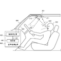
- FIG. 2 is a diagram illustrating a configuration of the voice processing system 200 according to the present embodiment.
- the voice processing system 200 is a system that suppresses noise mixed with the voice of an occupant who is a speaker of interest by using a microphone array arranged in the vehicle.
- the microphone array 201 includes a first microphone 211 and a second microphone 212 arranged on the ceiling between the speaker of interest 220 and the noise source region 230 in a direction connecting the speaker of interest 220 and the noise source region 230. Since the first microphone 211 is closer to the speaker of interest 220, the voice 250 of the speaker of interest 220 has a faster arrival time than the second microphone 212 and a large volume is input. On the other hand, since the second microphone 212 is closer to the noise source region 230, the noise 240 from the noise source region 230 has a faster arrival time than the first microphone 211, and a large volume is input.
- the mixed sound of the sound 250 and the noise 240 input to the first microphone 211 and the mixed sound of the sound 250 and the noise 240 input to the second microphone 212 are the arrival time of both sound and noise.
- the volume level is different and the mixing ratio is different. Therefore, noise is efficiently suppressed in the noise suppression unit that receives the first mixed signal and the second mixed signal output from the first microphone 211 and the second microphone 212, respectively.
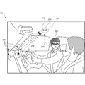
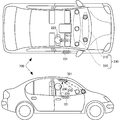
- FIG. 3A two left and right speakers 311 and 312 and three air conditioner outlets 321 to 323 in the left and right are present as a plurality of noise sources in front of the speaker of interest 220.
- the microphone array 301 is between the speaker of interest 220 and a plurality of noise sources, and the first microphone 302 and the second microphone 303 are arranged substantially parallel to the horizontal direction in which the plurality of noise sources are arranged. Has been placed. According to the arrangement of the speaker of interest 220, the plurality of noise sources, and the microphone array 301 as shown in FIG. 3A, the following problem occurs.
- the difference in the arrival time and volume of the noise input to the first microphone 302 and the second microphone 303 is the noise from the left and right speakers 311 and 312.
- the difference in distance from each noise source to the microphone is different.
- the noise from the three right and left air conditioner outlets 321 to 323 the difference in distance from each noise source to the microphone is different. Therefore, noise suppression must be considered with the two right and left speakers 311 and 312 and the three middle air conditioner outlets 321 to 323 as different noise sources as noise sources.
- the first microphone 302 and the second microphone 303 are approximately equidistant from the speaker of interest 220, so that the voice of the speaker of interest 220 reaches the voice.
- the first and second microphones 302 and 303 have substantially the same time and volume. 3A, since the distance from the noise source consisting of the speakers 311 and 312 to the first microphone 302 and the second microphone 303 is substantially equal, the noise source consisting of the speakers 311 and 312 is also clear.
- the first microphone 302 and the second microphone 303 have substantially the same noise arrival time and volume level. Accordingly, voice and noise are input to the first microphone 302 and the second microphone 303 with the same arrival time and volume.
- the noise from the noise source including the speakers 311 and 312 is suppressed, the voice of the speaker of interest 220 is suppressed.
- the voice of the speaker of attention 220 is emphasized, the noise from the noise source including the speakers 311 and 312 is suppressed. The noise suppression becomes inefficient.
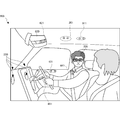
- FIG. 3B is a diagram showing an overview of the voice processing system 200 according to the present embodiment. It is a figure which shows the effect of the structure in the said FIG. In FIG. 3B, the same reference numerals are assigned to the same components as those in FIG.
- a noise source region 310 formed by two left and right speakers and a noise source region 320 formed by three right and left air conditioner outlets are formed by noise source groups arranged side by side toward the speaker of interest 220. This is shown as noise source region 230 in FIG.
- the first microphone 211 and the second microphone 212 of the microphone array 201 are arranged in a direction having a substantially equal distance difference with respect to each noise source. Therefore, in the noise source region 310 formed by two right and left speakers that are the same type of noise source, the distance from each speaker to the first microphone 211 and the distance from each speaker to the second microphone 212 are substantially equal.
- the installation position of the microphone array 201 in the vehicle front-rear direction and the inclination of the installation surface are reduced so that the difference between the distance from each noise source to the first microphone 211 and the distance from each noise source to the second microphone 212 is reduced. It is further desirable to adjust. In that case, the difference between the distance from each speaker to the first microphone 211 and the distance to the second microphone 212 is also substantially equal.
- the respective air outlets in the noise source area 320 by the three right and left air conditioner outlets As a result, the noise source region 310 by the two left and right speakers can be regarded as one noise source region, not individual noise sources. Similarly, the noise source region 320 formed by the three right and left air conditioner outlets can be regarded as one noise source region.
- FIG. 3B it can be considered that there are two noise source regions. Further, when the noise source region 310 by the two left and right speakers and the noise source region 320 by the three air conditioner outlets in the left and right are close to each other, the noise source region 310 and the noise source region 320 are combined into one noise source. It can also be regarded as an area.
- the first microphone 211 and the second microphone 212 have a difference in distance that is substantially equal to the distance between the first speaker 211 and the second speaker 212.
- the first microphone 211 and the second microphone 212 have different sound arrival times and volume levels.
- the difference between the distance from the first microphone 211 to the speaker of interest 220 and the distance from the second microphone 211 to the speaker of interest 220 is the noise source region from the first microphone 211.
- the difference between the distance from the second microphone 211 to the noise source region is the difference between the distance from the second microphone 211 to the noise source region.
- the arrival time of the voice of the speaker of interest 220 between the first microphone 211 and the second microphone 212 and the difference in volume are the arrival time of noise from the noise source area in the first microphone 211 and the second microphone 212, Different from the difference in volume. Accordingly, voice and noise are input to the first microphone 211 and the second microphone 212 at different mixing ratios. As a result, it is possible to efficiently perform noise suppression in the noise suppression unit according to the difference between the input and the mixture ratio.
- a noise source group area composed of a plurality of noise sources is treated as one noise source area.
- a mixed sound of noise from a noise source region including a plurality of noise sources arranged in a horizontal direction toward the speaker of interest and the voice of the speaker of interest is input, Multiple microphones that output mixed signals and noise signals are arranged side by side so that the difference in distance between each microphone and the speaker of interest differs from the difference in distance between each microphone and the noise source area.
- the arrangement of a plurality of microphones in such a microphone array is, for example, on a straight line passing through points projected on a plane (ceiling or door) on which any point in the noise source area and the speaker of interest are respectively installed on the microphone array. If it is in. Alternatively, it suffices if the noise source area and the speaker of interest are on a straight line connecting the areas and points projected on the plane (ceiling or door) where the microphone array is installed, respectively, at the shortest distance. Or what is necessary is just to be on the straight line which connects the points which projected the center of a noise source area
- on the straight line includes a position close to the straight line.
- the microphone interval in the microphone array is, for example, less than 10 cm, preferably in the range of about 2 cm to 4 cm.
- FIG. 4 is a block diagram showing a configuration of the voice processing system 200 according to the present embodiment.
- the same components as those in FIG. 4 are identical to FIG. 4, the same components as those in FIG. 4, the same components as those in FIG. 4, the same components as those in FIG.
- the first mixed signal (wiring 404) output from the first microphone 211 of the microphone array 201 and the second mixed signal (wiring 405) output from the second microphone 212 are the noise suppression unit 430 of the audio processing device 450. (See FIG. 5).
- the enhanced speech signal (wiring 431) that is an output signal from the noise suppression unit 430 is further processed by the control unit 440.
- the control unit 440 may perform voice recognition processing, voice reproduction processing, and the like.
- control unit 440 controls voice processing of the voice processing device 450.
- voice processing device 450 for example, when an occupant gives an instruction to output voice or music from a speaker or an instruction to start an air conditioner, noise suppression using the microphone array 201 is started. Therefore, when the sound output of the speaker is turned off or the air conditioner is turned off, only the first microphone 211 may be used, or control may be performed so as to perform an in-vehicle noise suppression process different from the present embodiment.
- control unit 440 may be a hardware configuration such as a logic array, or a software configuration in which a program is executed using a RAM by a CPU, and a firmware configuration in which these are combined.
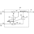
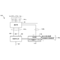
- FIG. 5 is a diagram illustrating a configuration of the noise suppression unit 430 according to the present embodiment.
- the noise suppression unit 430 includes a subtracter 501 that subtracts the estimated noise signal Y1 estimated to be mixed in the first mixed signal X1 from the first mixed signal X1. Moreover, it has the subtractor 503 which subtracts the estimated audio
- the adaptive filter XF 504 prevents the subtractor 501 from erroneously removing the voice signal of the speaker of interest 220 input to the second microphone 212 from the first mixed signal X1.
- the estimated noise signal Y1 is generated by processing the enhanced noise signal E2 by the adaptive filter NF502 using parameters that change based on the enhanced speech signal E1.
- the enhancement noise signal E2 is a signal obtained by subtracting the estimated audio signal Y2 by the subtractor 503 from the second mixed signal X2 transmitted from the second microphone 212 through the signal line.
- the estimated speech signal Y2 is generated by processing the enhanced speech signal E1 by the adaptive filter XF504 using parameters that change based on the enhanced noise signal E2.
- the noise suppression unit 430 may be an analog circuit, a digital circuit, or a mixed circuit thereof. If the noise suppression unit 430 is an analog circuit, the enhanced speech signal E1 is converted into a digital signal by an A / D converter when used for digital control. On the other hand, if the noise suppression unit 430 is a digital circuit, the signal from the microphone is converted into a digital signal by the A / D converter before entering the noise suppression unit 430. Further, when analog circuits and digital circuits are mixed, for example, the subtracters 501 and 503 are configured by analog circuits, and the adaptive filter NF502 and the adaptive filter XF504 are configured by analog circuits controlled by the digital circuit. Conceivable. Further, the noise suppression unit 430 in FIG.
- the adaptive filter XF 504 of FIG. 5 can be replaced with a circuit that outputs a constant level in order to filter the spread sound.
- the subtracters 501 and / or 503 can be replaced with an integrator by representing the estimated noise signal Y1 and the estimated speech signal Y2 by coefficients that are integrated with the first mixed signal X1 and the second mixed signal X2, respectively. is there. It is also possible to perform delay sum array processing and delay difference array processing on the first mixed signal X1 and the second mixed signal X2, and substitute the processed signal as an input to the noise suppression unit 430.
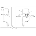
- the left diagram in FIG. 6B shows the sun visor 620 in use.
- the first microphone 622 and the second microphone 623 included in the microphone array 621 are arranged in the sun visor 620.
- the right diagram in FIG. 6B illustrates a case where the sun visor 620 is not used (attached to the ceiling in the vehicle). Regardless of the state of use of the sun visor 620, in order to prevent the sound from being blocked by the sun visor 620 to the first microphone 622 and the second microphone 623, a portion overlapping the first microphone 622 and the second microphone 623 (part of the sun visor) Process to pass through. For example, a hole 624 is made in a part of the sun visor 620 that overlaps the first microphone 622 and the second microphone 623. Then, the hole 624 is filled with a material 625 that can easily transmit sound such as a sponge material and blocks light.
- the positions of the two microphones are opposite between when the sun visor 620 is in use and when it is not in use, and a microphone that is close to the occupant who is the main speaker and a microphone that is close to the noise source. Are replaced. Therefore, it is desirable that the connection between each microphone and the input of the noise suppression unit 430 is switched by detecting the position of the sun visor 620. As shown in FIG. 6C, when the microphone array 621 is arranged on the upper ceiling of the sun visor 620, it is not necessary to switch the connection between each microphone and the input of the noise suppression unit 430 regardless of the usage state of the sun visor 620. .
- the present embodiment it is possible to efficiently perform noise suppression processing on the speech of the speaker of interest with respect to a plurality of noise sources such as a speaker and an air conditioner outlet that spread laterally toward the speaker of interest. .
- FIG. 7 is a diagram showing an outline of the voice processing system 700 according to the present embodiment.
- the same components as those in FIG. 3B are denoted by the same reference numerals, and description thereof is omitted.
- FIG. 8 is a block diagram showing the configuration of the speech processing apparatus 850 according to this embodiment.
- the selection unit 801 selects two outputs 801b to be input to the noise suppression unit 430 from outputs 801a from a plurality of microphones of the microphone arrays 701 and 731.
- the control unit 840 has a microphone selection table 841 (see FIGS. 9A to 9C), and corresponds to the speaker of interest and the noise source condition 840a, for example, the type of the driven noise source or the position of the speaker of interest.
- a selection signal 840b to the selection unit 801 is output based on the seat position and the noise source position. Note that the signal selection of the selection unit 801 may be performed by a gate based on each signal of the selection signal 840b, or may be selection based on a binary value of the selection signal 840b.
- an appropriate microphone may be selected in relation to the position of the speaker of interest 220 against noise from other noise sources such as noise from outside the vehicle when the window is opened.
- an instruction to open the passenger's window or the opening of the window may be detected to select an appropriate microphone.
- the microphone selection table 841A stores two microphones 913 to be selected in association with the combination of the seat position 911 and the noise source position 912 of the speaker of interest. In the case of the noise source regions 310 and 320, the noise source position 912 is fixed. When the window is opened or closed, the noise source position 912 changes.
- FIG. 9B is a diagram showing a configuration of the microphone selection table 841B according to the present embodiment.
- the microphone selection table 841B is another example of the microphone selection table 841 in FIG.
- the microphone selection table 841B is used in the control unit 840 to select a mixed signal output from the microphone in accordance with the position of the speaker of interest and the position of the noise source.
- the microphone selection table is not limited to the above three examples. There are no limitations as long as the algorithm selects two microphones appropriate for noise suppression.
- the speech processing system according to the present embodiment selects an appropriate microphone from the microphone array, which is the condition of the speaker of interest and the noise source, according to the frequency band of the speaker of interest and the noise source. And different in use. Since other configurations and operations are the same as those of the third embodiment, the same configurations and operations are denoted by the same reference numerals, and detailed description thereof is omitted.
- the selection of the microphone to be used according to the frequency band of the present embodiment can be combined with the selection of the microphone to be used according to the position of the speaker of interest or the noise source according to the third embodiment.
- FIG. 11 is a block diagram showing the configuration of the speech processing apparatus 1150 according to this embodiment.
- the same reference numerals are assigned to the functional configurations similar to those in FIG. 8, and description thereof is omitted.
- the control unit 1140 has a microphone selection table 1141 (see FIG. 12), and outputs a selection signal 1140b to the selection unit 801 based on the frequency band of speech of the speaker of interest and the frequency band of noise 1140a from the noise source. To do. Note that the signal selection of the selection unit 801 may be performed by a gate by each signal of the selection signal 1140b, or may be selection by a binary value of the selection signal 1140b.
- control unit 1140 controls noise suppression by the voice processing device 1150. For example, when an occupant instructs to output voice or music from a speaker or to start an air conditioner, noise suppression using two microphones of the microphone arrays 701 and 731 is started. Therefore, when the sound output of the speaker is turned off or the air conditioner is turned off, only one microphone may be used, or control may be performed so as to perform a vehicle interior noise suppression process different from the present embodiment.
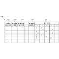
- the microphone selection table 1141 stores two microphones 1203 to be selected in association with the combination of the frequency band 1201 of noise generated from the noise source and the frequency band 1202 of the voice of the speaker of interest.
- the frequency band of noise from the noise source is known.
- FIG. 13 is a flowchart showing the processing procedure of the speech processing apparatus 1150 according to this embodiment. This flowchart is executed by the CPU of the voice processing apparatus 1150 using the RAM, and implements the functional components shown in FIG. In FIG. 13, the same steps as those in FIG. 10 are denoted by the same step numbers and the description thereof is omitted.
- step S1301 the voice processing device 1150 acquires the frequency band of noise from the noise source.
- step S1303 the speech processing apparatus 1150 acquires the frequency band of the speech of the speaker of interest.
- the audio processing device 1150 selects a microphone (or output signal) based on the noise and audio frequency bands.
- the speech processing system according to the present embodiment differs from the third embodiment and the fourth embodiment in that an appropriate microphone is selected and used based on the output of the noise suppression unit. Since other configurations and operations are the same as those in the third embodiment or the fourth embodiment, the same configurations and operations are denoted by the same reference numerals, and detailed description thereof is omitted.
- FIG. 14 is a block diagram showing the configuration of the speech processing apparatus 1450 according to this embodiment.
- the control unit 1440 has a microphone selection table 1441 (see FIG. 15), and outputs a selection signal 1440b to the selection unit 801 based on the enhanced speech signal 1440a that is the output of the noise suppression unit 430.
- the signal selection of the selection unit 801 may be performed by a gate based on each signal of the selection signal 1440b, or may be selected based on a binary value of the selection signal 1440b.
- control unit 1440 controls noise suppression by the voice processing device 1450.
- noise suppression using two microphones of the microphone arrays 701 and 731 is started. Therefore, when the sound output of the speaker is turned off or the air conditioner is turned off, only one microphone may be used, or control may be performed so as to perform a vehicle interior noise suppression process different from the present embodiment.
- an instruction to open the passenger's window or the opening of the window should be detected and an appropriate microphone selected. That's fine.
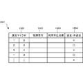
- FIG. 15 is a diagram showing a configuration of the microphone selection table 1441 according to the present embodiment.
- the microphone selection table 1441 is used in the control unit 1440 in order to select a mixed signal output from the microphone corresponding to the noise suppression effect determined from the feedback signal from the noise suppression unit 430.
- the microphone selection table 1441 stores the enhanced speech signal 1502 fed back from the noise suppression unit 430 and the noise suppression effect 1503 determined from the enhanced speech signal 1502 in association with the selected microphone pair 1501.
- the microphone selection table 1441 stores, as the selection / non-selection 1504, whether or not to use the selected microphone pair 1501 based on the noise suppression effect 1503.
- the microphone pair can be selected by selecting a microphone pair that has the largest noise suppression effect 1503. When the number of microphones in the microphone array is large, when the noise suppression effect 1503 exceeds a predetermined threshold, the microphone pair is selected, or the microphone pair that is predicted to have a high noise suppression effect is selected in advance.
- the suppression effect 1503 may be compared.
- FIG. 16 is a flowchart showing a processing procedure of the audio processing device 1450 according to the present embodiment. This flowchart is executed by the CPU of the voice processing device 1450 using the RAM, and implements the functional components shown in FIG. In FIG. 16, steps similar to those in FIG. 10 are denoted by the same step numbers and description thereof is omitted.
- step S1601 the voice processing device 1450 selects one of the microphone pairs to be tested for noise suppression.
- step S1603 the speech processing apparatus 1450 acquires the enhanced speech signal after noise suppression from the noise suppression unit 430, and stores it in the microphone selection table 1441.
- step S1605 the audio processing device 1450 determines whether all microphone pairs that need to be tested have been selected. Steps S1601 and S1603 are repeated until all the microphones are selected and the test is completed.
- the speech processing apparatus 1450 selects the mixed signal from the microphone pair having the highest noise suppression effect as the mixed signal to be input to the noise suppression unit 430 in step S1607.
- the speech processing system according to the present embodiment is different from the third to fifth embodiments in that a plurality of sets of microphones suitable for noise suppression are selected and used. Since other configurations and operations are the same as those of the third embodiment, the fourth embodiment, or the fifth embodiment, the same configurations and operations are denoted by the same reference numerals, and detailed description thereof is omitted.
- FIG. 17 is a block diagram showing the configuration of the audio processing device 1750 according to this embodiment.
- the same components as those in FIG. 8 are denoted by the same reference numerals, and description thereof is omitted.
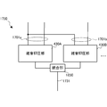
- the selection unit 1701 selects a plurality of mixed signal sets 1701a and 1701b to be input to the noise suppression unit 1730 from outputs 801a from a plurality of microphones of the microphone arrays 701 and 731.
- the number of microphone sets to be selected depends on how widely and finely the difference in the type of noise from a plurality of noise sources or the difference in type between the noise and the speech of interest is suppressed. In FIG. 17, two sets of three mixed signals that share one mixed signal are selected, but four mixed signals may be selected as two independent sets.
- the noise suppression unit 1730 suppresses noise from a plurality of mixed signal sets 1701a and 1701b. Then, the enhanced audio signal 1731 is output (see FIG. 18).
- the control unit 1740 has a microphone selection table 1741 (see FIGS. 19A and 19B), and a selection signal 1740b for selecting a plurality of sets to the selection unit 1701 based on a plurality of speakers of interest and a noise source condition 1740a. Output.
- a condition of a plurality of speakers or noise sources for example, the type of the driven noise source, the seat position or noise source position corresponding to the position of the speaker of interest, or the voice or noise source of the speaker of interest There is a frequency band of noise from.
- the signal selection of the selection unit 1701 may be performed by a gate based on each signal of the selection signal 1740b, or may be selected by a binary value of the selection signal 1740b.
- control unit 1740 controls noise suppression by the voice processing device 1750. For example, when an occupant instructs to output voice or music from a speaker or to start an air conditioner, noise suppression using two microphones of the microphone arrays 701 and 731 is started. Therefore, when the sound output of the speaker is turned off or the air conditioner is turned off, only one microphone may be used, or control may be performed so as to perform a vehicle interior noise suppression process different from the present embodiment.
- an appropriate microphone may be selected in relation to the position of the speaker of interest 220 against noise from other noise sources such as noise from outside the vehicle when the window is opened.
- an instruction to open the passenger's window or the opening of the window may be detected to select an appropriate microphone.
- the output 801a from the microphones of the microphone arrays 701 and 731 is selected by the selection unit 1701, but it may be configured to select and operate only appropriate microphones to be used.
- the input to the control unit 1740 has been described as a voice and noise frequency band, but voice and noise conditions that are not limited to this can be used.
- a plurality of microphones 2004 and 2005 are arranged in a direction perpendicular to a straight line passing through the speaker of interest 220 and the noise source regions 310 and 320. Further, a microphone 2006 may be optionally provided.
- the microphone matrix 2001 arranged in the vertical and horizontal directions is arranged on the ceiling in the vehicle.
- noise sources arranged in the horizontal direction toward the speaker of interest but also disturbances such as the voices of adjacent passengers can be suppressed, and accurate speech of the speaker of interest can be extracted.
- the voice processing system according to the present embodiment is different from the second to seventh embodiments in that the present invention is applied not to a vehicle but to a living room. Since other configurations and operations are the same as those in the second to seventh embodiments, the same configurations and operations are denoted by the same reference numerals, and detailed description thereof is omitted.
- FIG. 21 is a diagram showing an overview of a voice processing system 2100 according to this embodiment.
- a person (not shown) in the living room is a speaker of interest and a speaker of the television 2110 is a noise source.
- the microphone arrays 2111 to 2141 are composed of two microphones arranged in the direction connecting the speaker of interest and the noise source on the ceiling or the upper part of the wall between the speaker of interest and the noise source.
- the microphone arrays 2111 and 2131 suppress the noise of the television 2110 by emphasizing the voice of a person in front of the drawing.
- the microphone arrays 2121 and 2141 suppress the noise of the television 2110 by emphasizing the voice of a person near the sofa in front of the drawing.
- an appropriate microphone array is selected corresponding to the position of the speaker of interest.
- a person detection sensor may be provided to detect the position of the speaker of interest.
Landscapes
- Engineering & Computer Science (AREA)
- Physics & Mathematics (AREA)
- Health & Medical Sciences (AREA)
- Acoustics & Sound (AREA)
- Signal Processing (AREA)
- General Health & Medical Sciences (AREA)
- Mechanical Engineering (AREA)
- Otolaryngology (AREA)
- Audiology, Speech & Language Pathology (AREA)
- Computational Linguistics (AREA)
- Multimedia (AREA)
- Quality & Reliability (AREA)
- Human Computer Interaction (AREA)
- Circuit For Audible Band Transducer (AREA)
- Fittings On The Vehicle Exterior For Carrying Loads, And Devices For Holding Or Mounting Articles (AREA)
- Details Of Audible-Bandwidth Transducers (AREA)
- Obtaining Desirable Characteristics In Audible-Bandwidth Transducers (AREA)
Abstract
Priority Applications (4)
| Application Number | Priority Date | Filing Date | Title |
|---|---|---|---|
| EP14800753.7A EP3001417A4 (fr) | 2013-05-23 | 2014-01-16 | Système de traitement du son, procédé de traitement du son, programme de traitement du son, véhicule équipé d'un système de traitement du son et procédé d'installation de microphones |
| US14/892,396 US9905243B2 (en) | 2013-05-23 | 2014-01-16 | Speech processing system, speech processing method, speech processing program, vehicle including speech processing system on board, and microphone placing method |
| JP2015518093A JP6439687B2 (ja) | 2013-05-23 | 2014-01-16 | 音声処理システム、音声処理方法、音声処理プログラム、音声処理システムを搭載した車両、および、マイク設置方法 |
| EP21190767.0A EP3950433A1 (fr) | 2013-05-23 | 2014-01-16 | Procédé de traitement de la parole, procédé de traitement de la parole, programme de traitement de la parole et véhicule comprenant le système de traitement de la parole à bord |
Applications Claiming Priority (2)
| Application Number | Priority Date | Filing Date | Title |
|---|---|---|---|
| JP2013109006 | 2013-05-23 | ||
| JP2013-109006 | 2013-05-23 |
Publications (1)
| Publication Number | Publication Date |
|---|---|
| WO2014188735A1 true WO2014188735A1 (fr) | 2014-11-27 |
Family
ID=51933302
Family Applications (1)
| Application Number | Title | Priority Date | Filing Date |
|---|---|---|---|
| PCT/JP2014/050654 Ceased WO2014188735A1 (fr) | 2013-05-23 | 2014-01-16 | Système de traitement du son, procédé de traitement du son, programme de traitement du son, véhicule équipé d'un système de traitement du son et procédé d'installation de microphones |
Country Status (4)
| Country | Link |
|---|---|
| US (1) | US9905243B2 (fr) |
| EP (2) | EP3001417A4 (fr) |
| JP (1) | JP6439687B2 (fr) |
| WO (1) | WO2014188735A1 (fr) |
Cited By (3)
| Publication number | Priority date | Publication date | Assignee | Title |
|---|---|---|---|---|
| JP2018170718A (ja) * | 2017-03-30 | 2018-11-01 | 沖電気工業株式会社 | 収音装置、プログラム及び方法 |
| JP6854967B1 (ja) * | 2019-10-09 | 2021-04-07 | 三菱電機株式会社 | 雑音抑圧装置、雑音抑圧方法、及び雑音抑圧プログラム |
| WO2025150328A1 (fr) * | 2024-01-09 | 2025-07-17 | パナソニックIpマネジメント株式会社 | Système d'éclairage |
Families Citing this family (34)
| Publication number | Priority date | Publication date | Assignee | Title |
|---|---|---|---|---|
| US9641919B1 (en) | 2014-09-30 | 2017-05-02 | Amazon Technologies, Inc. | Audio assemblies for electronic devices |
| JP6592940B2 (ja) * | 2015-04-07 | 2019-10-23 | ソニー株式会社 | 情報処理装置、情報処理方法、及びプログラム |
| US9554207B2 (en) | 2015-04-30 | 2017-01-24 | Shure Acquisition Holdings, Inc. | Offset cartridge microphones |
| US9565493B2 (en) | 2015-04-30 | 2017-02-07 | Shure Acquisition Holdings, Inc. | Array microphone system and method of assembling the same |
| JP2017083600A (ja) * | 2015-10-27 | 2017-05-18 | パナソニックIpマネジメント株式会社 | 車載収音装置及び収音方法 |
| US10063967B2 (en) * | 2016-03-22 | 2018-08-28 | Panasonic Intellectual Property Management Co., Ltd. | Sound collecting device and sound collecting method |
| US10726835B2 (en) * | 2016-12-23 | 2020-07-28 | Amazon Technologies, Inc. | Voice activated modular controller |
| US10367948B2 (en) | 2017-01-13 | 2019-07-30 | Shure Acquisition Holdings, Inc. | Post-mixing acoustic echo cancellation systems and methods |
| US10838396B2 (en) * | 2017-04-18 | 2020-11-17 | Cisco Technology, Inc. | Connecting robotic moving smart building furnishings |
| US10522167B1 (en) * | 2018-02-13 | 2019-12-31 | Amazon Techonlogies, Inc. | Multichannel noise cancellation using deep neural network masking |
| CN108674344B (zh) * | 2018-03-30 | 2024-04-02 | 斑马网络技术有限公司 | 基于方向盘的语音处理系统及其应用 |
| CN111788627A (zh) * | 2018-04-09 | 2020-10-16 | 索尼公司 | 信号处理装置、信号处理方法和信号处理程序 |
| EP3804356A1 (fr) | 2018-06-01 | 2021-04-14 | Shure Acquisition Holdings, Inc. | Réseau de microphones à formation de motifs |
| US11297423B2 (en) | 2018-06-15 | 2022-04-05 | Shure Acquisition Holdings, Inc. | Endfire linear array microphone |
| US11310596B2 (en) | 2018-09-20 | 2022-04-19 | Shure Acquisition Holdings, Inc. | Adjustable lobe shape for array microphones |
| US11558693B2 (en) | 2019-03-21 | 2023-01-17 | Shure Acquisition Holdings, Inc. | Auto focus, auto focus within regions, and auto placement of beamformed microphone lobes with inhibition and voice activity detection functionality |
| TWI865506B (zh) | 2019-03-21 | 2024-12-11 | 美商舒爾獲得控股公司 | 具有抑制功能的波束形成麥克風瓣之自動對焦、區域內自動對焦、及自動配置 |
| EP3942842B1 (fr) | 2019-03-21 | 2026-03-11 | Shure Acquisition Holdings, Inc. | Boîtiers et caractéristiques de conception associées pour microphones matriciels de plafond |
| CN114051738B (zh) | 2019-05-23 | 2024-10-01 | 舒尔获得控股公司 | 可操纵扬声器阵列、系统及其方法 |
| CN114051637B (zh) | 2019-05-31 | 2025-10-28 | 舒尔获得控股公司 | 集成语音及噪声活动检测的低延时自动混波器 |
| WO2021041275A1 (fr) | 2019-08-23 | 2021-03-04 | Shore Acquisition Holdings, Inc. | Réseau de microphones bidimensionnels à directivité améliorée |
| WO2021087377A1 (fr) | 2019-11-01 | 2021-05-06 | Shure Acquisition Holdings, Inc. | Microphone de proximité |
| US11552611B2 (en) | 2020-02-07 | 2023-01-10 | Shure Acquisition Holdings, Inc. | System and method for automatic adjustment of reference gain |
| USD944776S1 (en) | 2020-05-05 | 2022-03-01 | Shure Acquisition Holdings, Inc. | Audio device |
| WO2021243368A2 (fr) | 2020-05-29 | 2021-12-02 | Shure Acquisition Holdings, Inc. | Systèmes et procédés d'orientation et de configuration de transducteurs utilisant un système de positionnement local |
| US11893985B2 (en) * | 2021-01-15 | 2024-02-06 | Harman International Industries, Incorporated | Systems and methods for voice exchange beacon devices |
| JP7814400B2 (ja) | 2021-01-28 | 2026-02-16 | シュアー アクイジッション ホールディングス インコーポレイテッド | ハイブリッドオーディオビーム形成システム |
| US12452584B2 (en) | 2021-01-29 | 2025-10-21 | Shure Acquisition Holdings, Inc. | Scalable conferencing systems and methods |
| US12542123B2 (en) | 2021-08-31 | 2026-02-03 | Shure Acquisition Holdings, Inc. | Mask non-linear processor for acoustic echo cancellation |
| US12289584B2 (en) | 2021-10-04 | 2025-04-29 | Shure Acquisition Holdings, Inc. | Networked automixer systems and methods |
| US12525083B2 (en) | 2021-11-05 | 2026-01-13 | Shure Acquisition Holdings, Inc. | Distributed algorithm for automixing speech over wireless networks |
| US12250526B2 (en) | 2022-01-07 | 2025-03-11 | Shure Acquisition Holdings, Inc. | Audio beamforming with nulling control system and methods |
| JP7819579B2 (ja) * | 2022-06-09 | 2026-02-25 | 株式会社デンソー | マイクシステム |
| US12598261B2 (en) | 2022-09-28 | 2026-04-07 | Shure Acquisition Holdings, Inc. | Wideband doubletalk detection for optimization of acoustic echo cancellation |
Citations (6)
| Publication number | Priority date | Publication date | Assignee | Title |
|---|---|---|---|---|
| JPH05173581A (ja) * | 1991-12-25 | 1993-07-13 | Mazda Motor Corp | 車両用騒音制御装置 |
| JPH0667691A (ja) * | 1992-08-18 | 1994-03-11 | Nec Corp | 雑音除去装置 |
| JP2003111185A (ja) * | 2001-09-27 | 2003-04-11 | Nippon Telegr & Teleph Corp <Ntt> | 収音装置 |
| JP2006222969A (ja) | 2005-02-09 | 2006-08-24 | Bose Corp | 車両通信 |
| JP2011007861A (ja) * | 2009-06-23 | 2011-01-13 | Fujitsu Ltd | 信号処理装置、信号処理方法、および信号処理プログラム |
| WO2012165657A1 (fr) * | 2011-06-03 | 2012-12-06 | 日本電気株式会社 | Système de traitement de paroles, dispositif de traitement de paroles, procédé de traitement de paroles et programme associé |
Family Cites Families (33)
| Publication number | Priority date | Publication date | Assignee | Title |
|---|---|---|---|---|
| DE4315000A1 (de) * | 1993-05-06 | 1994-11-10 | Opel Adam Ag | Geräuschkompensierte Freisprechanlage in Kraftfahrzeugen |
| US5715319A (en) * | 1996-05-30 | 1998-02-03 | Picturetel Corporation | Method and apparatus for steerable and endfire superdirective microphone arrays with reduced analog-to-digital converter and computational requirements |
| US6130949A (en) * | 1996-09-18 | 2000-10-10 | Nippon Telegraph And Telephone Corporation | Method and apparatus for separation of source, program recorded medium therefor, method and apparatus for detection of sound source zone, and program recorded medium therefor |
| US7062049B1 (en) * | 1999-03-09 | 2006-06-13 | Honda Giken Kogyo Kabushiki Kaisha | Active noise control system |
| US7146013B1 (en) * | 1999-04-28 | 2006-12-05 | Alpine Electronics, Inc. | Microphone system |
| US7447320B2 (en) * | 2001-02-14 | 2008-11-04 | Gentex Corporation | Vehicle accessory microphone |
| US8686922B2 (en) * | 1999-12-15 | 2014-04-01 | American Vehicular Sciences Llc | Eye-location dependent vehicular heads-up display system |
| CN1436436A (zh) * | 2000-03-31 | 2003-08-13 | 克拉里提有限公司 | 用于话音信号提取的方法和设备 |
| US20030160862A1 (en) * | 2002-02-27 | 2003-08-28 | Charlier Michael L. | Apparatus having cooperating wide-angle digital camera system and microphone array |
| US7003099B1 (en) * | 2002-11-15 | 2006-02-21 | Fortmedia, Inc. | Small array microphone for acoustic echo cancellation and noise suppression |
| JP4797330B2 (ja) * | 2004-03-08 | 2011-10-19 | 日本電気株式会社 | ロボット |
| DE102005002865B3 (de) * | 2005-01-20 | 2006-06-14 | Autoliv Development Ab | Freisprecheinrichtung für ein Kraftfahrzeug |
| US7995768B2 (en) * | 2005-01-27 | 2011-08-09 | Yamaha Corporation | Sound reinforcement system |
| GB2446619A (en) * | 2007-02-16 | 2008-08-20 | Audiogravity Holdings Ltd | Reduction of wind noise in an omnidirectional microphone array |
| DE602007004504D1 (de) * | 2007-10-29 | 2010-03-11 | Harman Becker Automotive Sys | Partielle Sprachrekonstruktion |
| EP2209693B1 (fr) | 2007-11-13 | 2013-04-03 | TK Holdings Inc. | Système et procédé pour recevoir une entrée sonore dans un véhicule |
| KR101189465B1 (ko) * | 2007-12-11 | 2012-10-12 | 현대자동차주식회사 | 차량용 마이크 |
| DE102008029352A1 (de) * | 2008-06-20 | 2009-12-31 | Fraunhofer-Gesellschaft zur Förderung der angewandten Forschung e.V. | Vorrichtung, Verfahren und Computerprogramm zum Lokalisieren einer Schallquelle |
| JP2010023534A (ja) * | 2008-07-15 | 2010-02-04 | Panasonic Corp | 騒音低減装置 |
| JP2010188752A (ja) * | 2009-02-16 | 2010-09-02 | Panasonic Corp | 騒音低減装置 |
| FR2945696B1 (fr) * | 2009-05-14 | 2012-02-24 | Parrot | Procede de selection d'un microphone parmi deux microphones ou plus, pour un systeme de traitement de la parole tel qu'un dispositif telephonique "mains libres" operant dans un environnement bruite. |
| KR20110047852A (ko) * | 2009-10-30 | 2011-05-09 | 삼성전자주식회사 | 동작 환경에 적응 가능한 음원녹음장치 및 그 방법 |
| EP2499839B1 (fr) * | 2009-11-12 | 2017-01-04 | Robert Henry Frater | Dispositiv mains-libres avec réseau de microphones |
| US8467551B2 (en) * | 2010-07-30 | 2013-06-18 | Gentex Corporation | Vehicular directional microphone assembly for preventing airflow encounter |
| US8525868B2 (en) * | 2011-01-13 | 2013-09-03 | Qualcomm Incorporated | Variable beamforming with a mobile platform |
| CN103460718A (zh) * | 2011-03-28 | 2013-12-18 | 株式会社尼康 | 电子设备以及信息传递系统 |
| US9215328B2 (en) * | 2011-08-11 | 2015-12-15 | Broadcom Corporation | Beamforming apparatus and method based on long-term properties of sources of undesired noise affecting voice quality |
| EP2566182A1 (fr) * | 2011-08-31 | 2013-03-06 | GN Resound A/S | Filtre de réduction de bruit du vent |
| CN103119461B (zh) * | 2011-09-20 | 2015-08-26 | 丰田自动车株式会社 | 声源检测装置 |
| JP5545676B2 (ja) * | 2011-11-07 | 2014-07-09 | 株式会社ホンダアクセス | 車室内のマイクアレイ配置構造 |
| JP5866997B2 (ja) | 2011-11-17 | 2016-02-24 | 凸版印刷株式会社 | フォトマスク及びカラーフィルタの製造方法 |
| EP3407621B1 (fr) * | 2012-06-29 | 2021-12-22 | FINEWELL Co., Ltd. | Écouteur stéréo |
| JP6074263B2 (ja) * | 2012-12-27 | 2017-02-01 | キヤノン株式会社 | 雑音抑圧装置及びその制御方法 |
-
2014
- 2014-01-16 WO PCT/JP2014/050654 patent/WO2014188735A1/fr not_active Ceased
- 2014-01-16 EP EP14800753.7A patent/EP3001417A4/fr not_active Ceased
- 2014-01-16 JP JP2015518093A patent/JP6439687B2/ja active Active
- 2014-01-16 US US14/892,396 patent/US9905243B2/en active Active
- 2014-01-16 EP EP21190767.0A patent/EP3950433A1/fr active Pending
Patent Citations (6)
| Publication number | Priority date | Publication date | Assignee | Title |
|---|---|---|---|---|
| JPH05173581A (ja) * | 1991-12-25 | 1993-07-13 | Mazda Motor Corp | 車両用騒音制御装置 |
| JPH0667691A (ja) * | 1992-08-18 | 1994-03-11 | Nec Corp | 雑音除去装置 |
| JP2003111185A (ja) * | 2001-09-27 | 2003-04-11 | Nippon Telegr & Teleph Corp <Ntt> | 収音装置 |
| JP2006222969A (ja) | 2005-02-09 | 2006-08-24 | Bose Corp | 車両通信 |
| JP2011007861A (ja) * | 2009-06-23 | 2011-01-13 | Fujitsu Ltd | 信号処理装置、信号処理方法、および信号処理プログラム |
| WO2012165657A1 (fr) * | 2011-06-03 | 2012-12-06 | 日本電気株式会社 | Système de traitement de paroles, dispositif de traitement de paroles, procédé de traitement de paroles et programme associé |
Non-Patent Citations (1)
| Title |
|---|
| See also references of EP3001417A4 |
Cited By (3)
| Publication number | Priority date | Publication date | Assignee | Title |
|---|---|---|---|---|
| JP2018170718A (ja) * | 2017-03-30 | 2018-11-01 | 沖電気工業株式会社 | 収音装置、プログラム及び方法 |
| JP6854967B1 (ja) * | 2019-10-09 | 2021-04-07 | 三菱電機株式会社 | 雑音抑圧装置、雑音抑圧方法、及び雑音抑圧プログラム |
| WO2025150328A1 (fr) * | 2024-01-09 | 2025-07-17 | パナソニックIpマネジメント株式会社 | Système d'éclairage |
Also Published As
| Publication number | Publication date |
|---|---|
| EP3001417A4 (fr) | 2017-05-03 |
| US20160111109A1 (en) | 2016-04-21 |
| JPWO2014188735A1 (ja) | 2017-02-23 |
| JP6439687B2 (ja) | 2018-12-19 |
| US9905243B2 (en) | 2018-02-27 |
| EP3001417A1 (fr) | 2016-03-30 |
| EP3950433A1 (fr) | 2022-02-09 |
Similar Documents
| Publication | Publication Date | Title |
|---|---|---|
| JP6439687B2 (ja) | 音声処理システム、音声処理方法、音声処理プログラム、音声処理システムを搭載した車両、および、マイク設置方法 | |
| JP2019133156A (ja) | 車両環境のためのマルチチャネル音声認識 | |
| US9883286B2 (en) | Managing telephony and entertainment audio in a vehicle audio platform | |
| EP2978242B1 (fr) | Système et procédé destines a atténuer une rétroaction audio | |
| EP2987312B1 (fr) | Système et procédé d'annulation d'écho acoustique | |
| US20160127827A1 (en) | Systems and methods for selecting audio filtering schemes | |
| JP6870078B2 (ja) | 動的サウンド調整のための雑音推定 | |
| CN105592384A (zh) | 用于控制车内噪声的系统和方法 | |
| US10728691B2 (en) | Apparatus and method for generating virtual venues for a listening room | |
| GB2577809A (en) | Method, apparatus and manufacture for two-microphone array speech enhancement for an automotive environment | |
| JP2025000703A (ja) | ハイブリッド車内スピーカ及びヘッドフォンベースの音響拡張現実システム | |
| JPWO2020003819A1 (ja) | 音声信号処理装置、移動装置、および方法、並びにプログラム | |
| JP6376132B2 (ja) | 音声処理システム、車両、音声処理ユニット、ステアリングホイールユニット、音声処理方法、ならびに音声処理プログラム | |
| EP4305620B1 (fr) | Déréverbération basée sur le type de média | |
| WO2018061956A1 (fr) | Appareil d'aide à la conversation et procédé d'aide à la conversation | |
| US20160255436A1 (en) | Techniques for sharing stereo sound between multiple users | |
| WO2019032543A1 (fr) | Système audio de véhicule avec présentation de contenu réverbéré | |
| JP2019080246A (ja) | 指向性制御装置および指向性制御方法 | |
| JP6753252B2 (ja) | 会話アシスト装置 | |
| JP2020140044A (ja) | 能動型騒音制御システム | |
| JP5116440B2 (ja) | 音制御装置 | |
| US20190007770A1 (en) | Sound volume control device, sound volume control method and program | |
| CN118860323A (zh) | 车载播放系统声道映射方法、装置、电子设备、存储介质及车辆 |
Legal Events
| Date | Code | Title | Description |
|---|---|---|---|
| 121 | Ep: the epo has been informed by wipo that ep was designated in this application |
Ref document number: 14800753 Country of ref document: EP Kind code of ref document: A1 |
|
| ENP | Entry into the national phase |
Ref document number: 2015518093 Country of ref document: JP Kind code of ref document: A |
|
| WWE | Wipo information: entry into national phase |
Ref document number: 14892396 Country of ref document: US |
|
| NENP | Non-entry into the national phase |
Ref country code: DE |
|
| WWE | Wipo information: entry into national phase |
Ref document number: 2014800753 Country of ref document: EP |