WO2014189131A1 - Procédé d'impression - Google Patents
Procédé d'impression Download PDFInfo
- Publication number
- WO2014189131A1 WO2014189131A1 PCT/JP2014/063710 JP2014063710W WO2014189131A1 WO 2014189131 A1 WO2014189131 A1 WO 2014189131A1 JP 2014063710 W JP2014063710 W JP 2014063710W WO 2014189131 A1 WO2014189131 A1 WO 2014189131A1
- Authority
- WO
- WIPO (PCT)
- Prior art keywords
- printing
- blanket
- speed
- substrate
- printing blanket
- Prior art date
- Legal status (The legal status is an assumption and is not a legal conclusion. Google has not performed a legal analysis and makes no representation as to the accuracy of the status listed.)
- Ceased
Links
Images


Classifications
-
- B—PERFORMING OPERATIONS; TRANSPORTING
- B41—PRINTING; LINING MACHINES; TYPEWRITERS; STAMPS
- B41F—PRINTING MACHINES OR PRESSES
- B41F17/00—Printing apparatus or machines of special types or for particular purposes, not otherwise provided for
- B41F17/001—Pad printing apparatus or machines
-
- B—PERFORMING OPERATIONS; TRANSPORTING
- B41—PRINTING; LINING MACHINES; TYPEWRITERS; STAMPS
- B41F—PRINTING MACHINES OR PRESSES
- B41F17/00—Printing apparatus or machines of special types or for particular purposes, not otherwise provided for
- B41F17/30—Printing apparatus or machines of special types or for particular purposes, not otherwise provided for for printing on curved surfaces of essentially spherical, or part-spherical, articles
- B41F17/34—Printing apparatus or machines of special types or for particular purposes, not otherwise provided for for printing on curved surfaces of essentially spherical, or part-spherical, articles on articles with surface irregularities, e.g. fruits, nuts
-
- B—PERFORMING OPERATIONS; TRANSPORTING
- B41—PRINTING; LINING MACHINES; TYPEWRITERS; STAMPS
- B41F—PRINTING MACHINES OR PRESSES
- B41F3/00—Cylinder presses, i.e. presses essentially comprising at least one cylinder co-operating with at least one flat type-bed
-
- B—PERFORMING OPERATIONS; TRANSPORTING
- B41—PRINTING; LINING MACHINES; TYPEWRITERS; STAMPS
- B41F—PRINTING MACHINES OR PRESSES
- B41F17/00—Printing apparatus or machines of special types or for particular purposes, not otherwise provided for
- B41F17/006—Printing apparatus or machines of special types or for particular purposes, not otherwise provided for for printing on curved surfaces not otherwise provided for
-
- B—PERFORMING OPERATIONS; TRANSPORTING
- B41—PRINTING; LINING MACHINES; TYPEWRITERS; STAMPS
- B41M—PRINTING, DUPLICATING, MARKING, OR COPYING PROCESSES; COLOUR PRINTING
- B41M1/00—Inking and printing with a printer's forme
- B41M1/02—Letterpress printing, e.g. book printing
-
- B—PERFORMING OPERATIONS; TRANSPORTING
- B41—PRINTING; LINING MACHINES; TYPEWRITERS; STAMPS
- B41M—PRINTING, DUPLICATING, MARKING, OR COPYING PROCESSES; COLOUR PRINTING
- B41M1/00—Inking and printing with a printer's forme
- B41M1/02—Letterpress printing, e.g. book printing
- B41M1/04—Flexographic printing
-
- B—PERFORMING OPERATIONS; TRANSPORTING
- B41—PRINTING; LINING MACHINES; TYPEWRITERS; STAMPS
- B41M—PRINTING, DUPLICATING, MARKING, OR COPYING PROCESSES; COLOUR PRINTING
- B41M1/00—Inking and printing with a printer's forme
- B41M1/10—Intaglio printing ; Gravure printing
-
- B—PERFORMING OPERATIONS; TRANSPORTING
- B41—PRINTING; LINING MACHINES; TYPEWRITERS; STAMPS
- B41M—PRINTING, DUPLICATING, MARKING, OR COPYING PROCESSES; COLOUR PRINTING
- B41M1/00—Inking and printing with a printer's forme
- B41M1/40—Printing on bodies of particular shapes, e.g. golf balls, candles, wine corks
Definitions
- the present invention relates to a printing method, and more particularly, to a printing method using a printing blanket for printing transferred ink on a substrate.
- the printing method using a printing blanket is to press the printing blanket (same as the transfer blanket) against the printing original plate (same as the printing plate), and print the ink placed in the pattern corresponding to the printing pattern on the printing original plate.
- the printing blanket is transferred (transferred), and then the printing blanket is pressed against the printing surface, and the transferred ink is transferred to the printing surface, thereby printing the printing pattern on the printing surface.
- an invention is disclosed in which the ink in the ink box in contact with the printing original plate is shaken, stirred and hardened by reciprocating the printing original plate ( For example, see Patent Document 1).
- a blanket for printing is an elastic body such as silicon rubber mixed with silicon oil to give elasticity (flexibility), and the tip is a semicircular or semi-cylindrical smooth curved surface (approximately regarded as an arc.
- the tip (corresponding to the South Pole) is moved up and down. That is, when the printing blanket is initially pressed against the printing original plate, a narrow range of the tip comes into contact with the surface of the printing original plate, and as the pressing proceeds, the range of contact with the surface of the printing original plate increases. Similarly, at the beginning when the printing blanket is pressed against the surface of the printing medium, the narrow range of the tip is in contact with the surface of the printing medium, and as the pressing proceeds, the area where the printing material is in contact with the surface of the printing medium Will expand.
- the wedge shape with an extremely small opening angle between the surface of the front end of the printing blanket and the surface of the printing original plate (apparent cross-section arc surface and plane) Space) is formed.
- a wedge-shaped space having a very small opening angle is formed between the surface at the front end of the printing blanket and the surface of the printing medium.
- the leading edge of the printing blanket is pushed by the surface of the printing original plate and deformed into a flat shape, and the range away from the leading edge (corresponding to the range close to the equator) is It expands to the periphery and deforms to increase the apparent radius of curvature. For this reason, there is an apparent gap between the tip region deformed into a flat shape and a region away from the tip region deformed so that the apparent radius of curvature is large (in this case, approaching the printing original plate). A curved surface having a smaller radius of curvature is formed.
- a wedge-shaped space having a large opening angle is formed between the curved surface having a small apparent radius of curvature and the surface of the printing original plate.
- a curved surface having a smaller apparent radius of curvature is formed on the printing blanket, and the surface between the curved surface having a smaller apparent radius of curvature and the surface of the printing original plate is formed.
- a wedge-shaped space having a large opening angle is formed.
- the printing blanket In order to prevent air from being caught between the surface of the printing blanket, the surface of the printing original plate, and the surface of the substrate, the printing blanket was made smaller and the curvature radius of the tip was reduced. In order to cover the printing pattern, it is necessary to increase the height of the printing blanket to make it a softer material, leading to an increase in printing cost and deterioration in printing efficiency. Also, in order to prevent air from being caught between the surface of the printing blanket and the surface of the printing original plate and the surface of the printing medium, the speed of pressing the printing blanket against the printing original plate and the printing body was slowed down. However, since the printing time is extended, the printing efficiency is deteriorated and the productivity (mass productivity) is reduced.
- the present invention solves the above-mentioned problem, and air is trapped between the surface of the printing blanket, the surface of the printing original plate, and the surface of the printing medium while suppressing increase in printing cost and deterioration of printing efficiency. It is to obtain a printing method that prevents it.
- the ink is transferred to the printing blanket by pressing a printing blanket made of an elastic body that becomes thinner toward the tip, against the printing original plate on which the ink is applied,
- a printing method for printing the ink on the substrate by pressing the printing blanket onto which the ink has been transferred When the printing blanket is pressed against the printing original plate, the lowering speed when the tip of the printing blanket starts to contact the surface of the printing original plate is slowed down, and the lowering speed is increased as the pressing proceeds. It is characterized by.
- the lowering speed when the tip of the printing blanket starts to contact the surface of the printing original plate is such that the pressing of the printing blanket onto the printing original plate is completed, It is 10 to 15% of the ascending speed when the printing blanket is separated from the printing original plate, and the descending speed is increased to 50 to 60% of the ascending speed as the pressing proceeds.
- the printing blanket is once stopped to descend, and then lowered. It is characterized by increasing the speed.
- the ink is transferred to the printing blanket by pressing a printing blanket made of an elastic body that becomes thinner toward the leading end against the printing original plate to which the ink is applied.
- a printing method for printing the ink on the substrate by pressing the printing blanket onto which the ink has been transferred, When pressing the printing blanket against the substrate, the descending speed when the tip of the printing blanket starts to contact the surface of the substrate is slowed down, and the descending speed is increased as the pressing proceeds. It is characterized by.
- the lowering speed when the front end of the printing blanket starts to contact the surface of the printing material is such that the pressing of the printing blanket to the printing material is completed, It is 10 to 15% of the rising speed when the printing blanket is separated from the substrate, and the lowering speed is increased to 50 to 60% of the rising speed as the pressing proceeds.
- the descent of the printing blanket is once stopped, and then the descent is performed after the stop. It is characterized by increasing the speed.
- the lowering speed when the position excluding the tip of the printing blanket starts to contact the surface of the substrate is the slowest, and as the pressing proceeds, the lowering rate is increased. It is characterized by speeding up.
- the ink is transferred to the printing blanket by pressing a printing blanket made of an elastic body, which becomes thinner toward the tip, against the printing original plate to which the ink has been applied.
- a printing method of printing the ink on the substrate by pressing the printing blanket against the substrate When pressing the printing blanket against the substrate, when the radius of curvature at a predetermined position on the side surface of the printing blanket approaches the radius of curvature of the substrate at which the predetermined position is pressed, the printing blanket It is characterized by slowing the descending speed.
- the curvature radius (Rb) of the position where the side surface of the printing blanket is pressed against the printed material is the curvature radius of the position where the side surface of the printing blanket is pressed on the printed material. It is characterized by being larger than half of (Rp) and smaller than the radius of curvature (Rp) (Rp / 2 ⁇ Rb ⁇ Rp).
- the printing blanket speed when the printing blanket lowering speed is slowed is the rising speed when the printing blanket is separated from the substrate. 10 to 15%, and the speed of the printing blanket when the printing blanket descending speed is increased is 50 to 60% of the ascending speed when the printing blanket is separated from the substrate.
- the printing method according to the present invention increases the descending speed after the leading edge of the printing blanket starts to contact the surface of the printing original plate or the surface of the substrate. Therefore, the extension of the printing time is suppressed, and the deterioration of the printing efficiency and the productivity (mass productivity) are prevented.
- the lowering speed at the beginning of pressing is set to about 1/6 to 1/3 of the lowering speed at the end of pressing, so that the air can be prevented from being trapped and the manufacturing efficiency can be prevented from being significantly reduced. Is done.
- the lowering of the printing blanket is temporarily stopped, so the surface of the printing blanket and the surface of the printing original plate or the surface of the substrate The air can be further prevented from getting in between.
- work shown in FIG. The side view explaining the transfer process in the printing method which concerns on Embodiment 1 of this invention.
- FIG. 1A and 1B illustrate a printing method according to Embodiment 1 of the present invention, in which FIG. 1A is a flowchart showing a work flow, and FIG. 1B is a side view schematically showing the work flow.
- the printing method 100 includes an application step (S1) in which the ink 2 is attached to the printing original plate 10 so as to have a predetermined printing pattern 1 (see FIG.
- a transfer step (S2) in which a printing blanket (hereinafter referred to as “blanket”) 20 is pressed against the printing original plate 10 on which the ink 2 is adhered to the printing pattern 1 to transfer the ink 2 to the blanket 20;
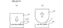
- a printing step (S3) in which the blanket 20 to which the ink 2 has been transferred is pressed against the printing surface 30 (the same as the surface of the substrate to be printed), and the ink 2 transferred to the blanket 20 is transferred to the printing surface 30;
- a cleaning step (S4) in which the blanket 20 after the ink 2 is transferred to the printing surface 30 is pressed against the flat cleaning surface 40, and the ink 2 remaining on the blanket 20 is adhered to the cleaning surface 40; Furthermore, the surface activation process in which the blanket 20 after the remaining ink 2 adheres to the cleaning surface 40 is pressed against the moisture absorbent 50 and a part of the water or solvent that has soaked into the moisture absorbent 50 adheres or soaks into the blanket 20.
- the blanket 20 in which a part of water or solvent is adhered or soaked is air blown to remove a part of the water or solvent, or the blanket 20 is pressed against a flat dry surface, A part of the water or solvent adhering to or soaking into the blanket 20 may be removed.
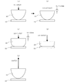
- FIG. 2 to 6 are side views showing the state of work corresponding to the flow of work for explaining the printing method according to Embodiment 1 of the present invention.
- FIG. 2 is a coating process
- FIG. 3 is a transfer process
- FIG. 4 is a printing process
- FIG. 5 is a cleaning process
- FIG. 6 is a surface activation process.
- the ink 2 is applied to the entire surface of the printing original plate 10 to a uniform thickness by the roller 3, and the ink 2 applied to the substantially entire surface is partially removed.
- the remaining ink 2 (the film thickness is exaggerated and hatched) is the printing pattern 1 (letter printing).
- the ink 2 may be partially repelled by impregnating the printing original plate 10 with water or the like corresponding to the printing pattern 1.
- a masking material 10a is installed on the entire surface of the printing original plate 10, and in FIG. 2C, a concave portion 10b corresponding to the printing pattern 1 is formed on the masking material 10a.
- the recess 10b is filled with ink 2 (intaglio printing).
- the ink 2 may be partially applied to the printing original plate 10 corresponding to the printing pattern 1 and the ink 2 may be partially repelled.
- the point which adheres the ink 2 so that it may become the predetermined printing pattern 1 to the printing original plate 10 is not limited, So-called relief printing or intaglio printing may be sufficient.
- the cleaning step (S 4) In FIG. 5, in the cleaning step (S 4), the blanket 20 after the ink 2 is transferred to the printing surface 30 is pressed against the flat cleaning surface 40, and the ink 2 remaining on the blanket 20 is adhered to the cleaning surface 40. ing.
- the cleaning surface 40 is paper or adhesive tape, but is not limited thereto.
- the blanket 20 after cleaning is pressed against the hygroscopic material 50, and a part of the water or solvent soaked in the hygroscopic material 50 is attached to or soaked into the blanket 20.
- the hygroscopic material 50 is, for example, a sheet in which about 50 sheets of paper are laminated and impregnated with water or a solvent (impregnated), but is limited to paper as long as it has hygroscopicity. It is not a thing. Further, instead of laminating a plurality of sheets, one sheet (one layer) may be used.
- the solvent is appropriately selected according to the properties of the ink 2 and has a property of softening the hard ink 2, for example, thinner, xylene, toluene, etc., but is not limited thereto. Absent.
- FIGS. 7A and 7B are side views for explaining a transfer process in the printing method according to the first embodiment of the present invention.
- FIG. 7A is a state of contact
- FIG. 7B is a state immediately after the start of contact
- FIG. d) is when contact is completed
- (e) is when separated.
- the blanket 20 is lowered toward the printing original plate 10 at a predetermined speed V, and when the blanket 20 starts to contact the printing original plate 10 (more precisely, Immediately before contact, the lowering speed of the blanket 20 is reduced (for example, 10 to 15% of the speed V).
- FIG. 7B when the blanket 20 is slightly in contact with the printing original plate 10 (for example, pressed about 0.5 to 1.0 mm), the lowering of the blanket 20 is temporarily stopped (for example, 0.5). ⁇ 1.0 seconds).
- the pressing of the blanket 20 to the printing original plate 10 is advanced while gradually increasing the descending speed (for example, the pressing amount is 10 to 20 mm).
- the lowering speed of the blanket 20 is sufficiently increased (for example, 50 to 60% of the speed V).
- the blanket 20 is raised and separated from the printing original plate 10. At this time, the rising speed of the blanket 20 is the same as the speed V (100% of the speed V).
- FIG. 8 is a side view for explaining the contact area between the blanket and the printing original plate in the transfer step in the printing method according to Embodiment 1 of the present invention.
- the blanket 20 when the blanket 20 is lowered by a distance H from a state where the blanket 20 and the printing original plate 10 are in contact with each other in a range S (indicated by hatching) up to the position A, both of them reach the position B on one side. It is assumed that contact is made in the contact range (S + ⁇ S).
- the surface of the blanket 20 has a curvature radius R (center O), and the angle AOB is “ ⁇ ”.
- the descending speed is decreased. Therefore, since the distance H per unit time in the above formula is small, the contact range increment ⁇ S per unit time is small. Therefore, the time for the air to escape from the wedge-shaped space formed between the surface of the blanket 20 and the surface of the printing original plate at the time of contact and immediately after the contact is secured, so that the surface of the blanket 20 and the printing original plate are secured. The air can be prevented from being caught between the surfaces. Therefore, the printing blanket is made small, the tip radius of curvature is small, the height is high, and the material is softer, so that the printing cost and the printing efficiency are not deteriorated. Therefore, an inexpensive and high-quality printed material can be obtained.
- the descending speed is increased. Since the distance H is larger, the contact range increment ⁇ S per unit time does not vary significantly. Therefore, even if the descending speed is increased, the atmospheric air is prevented from being caught between the surface of the blanket 20 and the surface of the printing original plate. Also, since the descending speed is increased at the point where contact has progressed, the printing time can be prevented from being extended compared to the case where the descending speed is slowed down throughout the entire contact process. Reduction in (mass productivity) is suppressed.
- the magnitude of the descending speed at the time of contact (to make it slower), the magnitude of the descending speed at the end of contact (to make it faster), the timing to change the descending speed, and the changing procedure (gradual change or step) Change) is not limited.
- the speed V that descends due to the contact may be different from the speed that rises when the contact is completed and separated from the printing original plate 10.
- the lowering of the blanket 20 is temporarily stopped at a slight contact, but the present invention is not limited to this, and may not be temporarily stopped.
- FIG. 9 is a side view showing a printing process for explaining a printing method according to Embodiment 2 of the present invention, where (a) is in contact, (b) is immediately after the start of contact, and (c) is in progress of contact. Middle, (d) is when contact is completed, and (e) is when separated.
- the same parts as those in the first embodiment are denoted by the same reference numerals, and a part of the description is omitted.
- the surface to be printed is shown with a hole having a circular cross section, but the present invention is not limited to this, and a hole with a bottom, that is, a concave portion.
- the cross-sectional shape may not be circular.
- a circular hole 61 is formed on the printing surface 60, and the boundary between the printing surface 60 and the hole 61 is referred to as a hole peripheral edge 62.
- the blanket 20 is lowered toward the printing surface 60 at a predetermined speed V, and when the blanket 20 starts to contact the hole peripheral edge 62 of the printing surface 60 (precisely, contact) Immediately before, the lowering speed of the blanket 20 is decreased (for example, 5 to 10% of the speed V).
- the blanket 20 slightly contacts the hole peripheral edge 62 of the printing surface 60 (for example, when it is pressed by about 0.5 to 1.0 mm), the lowering of the blanket 20 is temporarily stopped ( For example, 0.5 to 1.0 seconds).
- the pressing of the blanket 20 against the printing surface 60 is advanced while gradually increasing the descending speed (for example, the pressing amount is 10 to 20 mm).
- the lowering speed of the blanket 20 is sufficiently increased (for example, 50 to 60% of the speed V).
- the pressing of the blanket 20 to the printing surface 60 is completed, the blanket 20 is raised and separated from the printing surface 60. At this time, the rising speed of the blanket 20 is the same as the speed V (100% of the speed V).
- the printing method 200 of the present invention when the blanket 20 starts to contact the hole peripheral edge 62 of the printing surface 60 and immediately after the contact, the descending speed is decreased and the contact range increment ⁇ S per unit time becomes small. ing. Therefore, at the time of contact and immediately after the contact, the time for the air to escape from the wedge-shaped space formed between the surface of the blanket 20 and the surface of the printing surface 60 is secured, so that the surface of the blanket 20 The air is prevented from being caught between the printing surface 60 and the surface. Therefore, similarly to the first embodiment, it is possible to obtain an inexpensive and high-quality printed material.
- FIG. 10 is a side view showing a printing process for explaining a printing method according to Embodiment 3 of the present invention, where (a) is just after the start of contact, (b) and (c) are in progress of contact, d) is immediately before the end of the contact, and (e) is the time of separation.
- the same parts as those in the first embodiment are denoted by the same reference numerals, and a part of the description is omitted.
- the surface to be printed is formed with an annular projecting surface having a smooth skirt, but the present invention is not limited to this, and a partial surface is shown. It may be a protrusion or a protrusion on a line, and each quantity and arrangement form (in the case of plural, symmetric or asymmetric) may be any.
- the printing surface 70 includes a flat portion 71 and an annular projecting surface portion 73, and the flat surface portion 71 and the projecting surface portion 73 are connected by a corner 72 having an arcuate cross section. Yes.
- the radius of curvature in the cross section of the corner 72 is referred to as “Rp”.
- the pressing of the blanket 20 against the flat surface 71 of the printing surface 70 is advanced while gradually increasing the descending speed (for example, the pressing amount is 10 to 20 mm).
- the lowering speed of the blanket 20 is sufficiently increased (for example, 50 to 60% of the speed V) until the blanket 20 reaches the corner 72 of the printing surface 70.
- the radius of curvature of the cross section of the portion pressed against the corner 72 of the side surface of the blanket 20 is “Rb”
- the radius of curvature Rb is larger than half of the radius of curvature Rp of the cross section of the corner 72, and the radius of curvature Rp (Rp / 2 ⁇ Rb ⁇ Rp).
- the blanket 20 is raised and separated from the printing surface 70. At this time, the rising speed of the blanket 20 is the same as the speed V (100% of the speed V).
- the lowering speed is decreased and then the lowering speed is increased.
- the descending speed is again slowed. Since the increment ⁇ S (not shown) of the contact range per unit time becomes small, a wedge shape is formed between the surface of the blanket 20 and the surface of the printing surface 70 (the flat surface portion 71, the corner portion 72, and the protruding surface portion 73). Since the time for the atmosphere to escape from the space is secured, the air can be prevented from being caught between the surface of the blanket 20 and the surface of the printing surface 70. Therefore, similarly to the first embodiment, it is possible to obtain an inexpensive and high-quality printed material.
- the present invention it is possible to prevent air from being caught between the surface of the blanket and the surface of the printing original plate, and from being caught between the surface of the blanket and the surface of the printing medium. It can be widely used as a printing method using blankets of various forms (shape, size, material, etc.).
Landscapes
- Engineering & Computer Science (AREA)
- Mechanical Engineering (AREA)
- Printing Methods (AREA)
- Inking, Control Or Cleaning Of Printing Machines (AREA)
Abstract
Priority Applications (5)
| Application Number | Priority Date | Filing Date | Title |
|---|---|---|---|
| JP2014560581A JP5916903B2 (ja) | 2013-05-23 | 2014-05-23 | 印刷方法 |
| KR1020147035619A KR101694600B1 (ko) | 2013-05-23 | 2014-05-23 | 인쇄 방법 |
| US14/413,047 US9321255B2 (en) | 2013-05-23 | 2014-05-23 | Printing method |
| EP14800613.3A EP3000606B1 (fr) | 2013-05-23 | 2014-05-23 | Procédé d'impression |
| CN201480001625.8A CN104540683B (zh) | 2013-05-23 | 2014-05-23 | 印刷方法 |
Applications Claiming Priority (4)
| Application Number | Priority Date | Filing Date | Title |
|---|---|---|---|
| JP2013-108620 | 2013-05-23 | ||
| JP2013108620A JP2014226859A (ja) | 2013-05-23 | 2013-05-23 | 印刷方法 |
| JPPCT/JP2013/076573 | 2013-09-30 | ||
| PCT/JP2013/076573 WO2014188611A1 (fr) | 2013-05-23 | 2013-09-30 | Procédé d'impression |
Publications (1)
| Publication Number | Publication Date |
|---|---|
| WO2014189131A1 true WO2014189131A1 (fr) | 2014-11-27 |
Family
ID=51933191
Family Applications (2)
| Application Number | Title | Priority Date | Filing Date |
|---|---|---|---|
| PCT/JP2013/076573 Ceased WO2014188611A1 (fr) | 2013-05-23 | 2013-09-30 | Procédé d'impression |
| PCT/JP2014/063710 Ceased WO2014189131A1 (fr) | 2013-05-23 | 2014-05-23 | Procédé d'impression |
Family Applications Before (1)
| Application Number | Title | Priority Date | Filing Date |
|---|---|---|---|
| PCT/JP2013/076573 Ceased WO2014188611A1 (fr) | 2013-05-23 | 2013-09-30 | Procédé d'impression |
Country Status (7)
| Country | Link |
|---|---|
| US (1) | US9321255B2 (fr) |
| EP (1) | EP3000606B1 (fr) |
| JP (2) | JP2014226859A (fr) |
| KR (1) | KR101694600B1 (fr) |
| CN (1) | CN104540683B (fr) |
| TW (1) | TWI558577B (fr) |
| WO (2) | WO2014188611A1 (fr) |
Families Citing this family (4)
| Publication number | Priority date | Publication date | Assignee | Title |
|---|---|---|---|---|
| US10800197B2 (en) | 2016-05-17 | 2020-10-13 | Shuhou Co., Ltd. | Printing blanket |
| KR102100669B1 (ko) | 2016-09-27 | 2020-05-27 | (주)엘지하우시스 | 차량용 내장재의 제조방법 및 차량용 내장재 |
| WO2018078694A1 (fr) * | 2016-10-24 | 2018-05-03 | 株式会社秀峰 | Dispositif d'activation de blanchet d'impression et procédé d'impression utilisant un blanchet d'impression |
| US12459247B2 (en) | 2022-04-28 | 2025-11-04 | Shuhou Co., Ltd. | Printing apparatus and method for producing printed item |
Citations (6)
| Publication number | Priority date | Publication date | Assignee | Title |
|---|---|---|---|---|
| JPS5363111A (en) * | 1976-11-15 | 1978-06-06 | Hamasawa Kogyo Kk | Automatic printer |
| JPS62501829A (ja) * | 1985-01-07 | 1987-07-23 | タンポフレックス・ゲゼルシャフト・ミット・ベシュレンクテル・ハフツンク | タンポン高速印刷方法 |
| JPS63128941A (ja) * | 1986-11-19 | 1988-06-01 | Taihei Kogyo Kk | パツド印刷機における転写パツド駆動装置 |
| JPH11268497A (ja) * | 1998-03-19 | 1999-10-05 | Nissha Printing Co Ltd | 屋内用化粧材とその製造方法 |
| JP2005212109A (ja) * | 2004-01-27 | 2005-08-11 | Fuji Photo Film Co Ltd | パッド支持体駆動装置およびこれを備えたサーボモータ駆動型パッド印刷機。 |
| JP2008114496A (ja) | 2006-11-06 | 2008-05-22 | Fujifilm Corp | インキ密閉型パッド印刷機 |
Family Cites Families (9)
| Publication number | Priority date | Publication date | Assignee | Title |
|---|---|---|---|---|
| US4779531A (en) * | 1987-01-29 | 1988-10-25 | Teihi Kogyo Kabushiki Kaisha | Hand operated pad printing machine |
| US5272973A (en) * | 1993-01-22 | 1993-12-28 | United Silicone Inc. | Inkcup assembly and drive mechanism for pad printing machine |
| DE602004014002D1 (de) * | 2004-12-10 | 2008-07-03 | Essilor Int | Stempel zum Auftragen eines Motivs, Verfahren zur Stempelherstellung und Verfahren zur Herstellung eines Objekts anhand von diesem Stempel |
| US8151704B2 (en) * | 2008-02-21 | 2012-04-10 | Bridgestone Sports Co., Ltd | Method for printing on spherical object and pad to be used therefor |
| US20100116159A1 (en) * | 2008-11-13 | 2010-05-13 | Larry Hines | Offset Printing Unit with Plate Cylinder Drive |
| FR2948061B1 (fr) * | 2009-07-15 | 2011-09-02 | Goss Int Montataire Sa | Procede de reglage de la vitesse angulaire de cylindres d'impression |
| DE102010012280A1 (de) * | 2010-03-22 | 2011-09-22 | Heidelberger Druckmaschinen Ag | Verfahren zum Wechseln von Druckplatten in Rotationsdruckmaschinen mit mehreren Druckwerken |
| KR101263253B1 (ko) * | 2010-11-24 | 2013-05-10 | 삼성전자주식회사 | 롤 프린팅 장치 |
| JP5766465B2 (ja) * | 2011-02-28 | 2015-08-19 | 順 阪本 | 印刷機、印刷装置および印刷方法 |
-
2013
- 2013-05-23 JP JP2013108620A patent/JP2014226859A/ja active Pending
- 2013-09-30 WO PCT/JP2013/076573 patent/WO2014188611A1/fr not_active Ceased
-
2014
- 2014-05-23 US US14/413,047 patent/US9321255B2/en active Active
- 2014-05-23 WO PCT/JP2014/063710 patent/WO2014189131A1/fr not_active Ceased
- 2014-05-23 CN CN201480001625.8A patent/CN104540683B/zh active Active
- 2014-05-23 TW TW103118029A patent/TWI558577B/zh active
- 2014-05-23 EP EP14800613.3A patent/EP3000606B1/fr active Active
- 2014-05-23 JP JP2014560581A patent/JP5916903B2/ja active Active
- 2014-05-23 KR KR1020147035619A patent/KR101694600B1/ko active Active
Patent Citations (6)
| Publication number | Priority date | Publication date | Assignee | Title |
|---|---|---|---|---|
| JPS5363111A (en) * | 1976-11-15 | 1978-06-06 | Hamasawa Kogyo Kk | Automatic printer |
| JPS62501829A (ja) * | 1985-01-07 | 1987-07-23 | タンポフレックス・ゲゼルシャフト・ミット・ベシュレンクテル・ハフツンク | タンポン高速印刷方法 |
| JPS63128941A (ja) * | 1986-11-19 | 1988-06-01 | Taihei Kogyo Kk | パツド印刷機における転写パツド駆動装置 |
| JPH11268497A (ja) * | 1998-03-19 | 1999-10-05 | Nissha Printing Co Ltd | 屋内用化粧材とその製造方法 |
| JP2005212109A (ja) * | 2004-01-27 | 2005-08-11 | Fuji Photo Film Co Ltd | パッド支持体駆動装置およびこれを備えたサーボモータ駆動型パッド印刷機。 |
| JP2008114496A (ja) | 2006-11-06 | 2008-05-22 | Fujifilm Corp | インキ密閉型パッド印刷機 |
Also Published As
| Publication number | Publication date |
|---|---|
| EP3000606A1 (fr) | 2016-03-30 |
| JP5916903B2 (ja) | 2016-05-11 |
| JP2014226859A (ja) | 2014-12-08 |
| TW201511975A (zh) | 2015-04-01 |
| US9321255B2 (en) | 2016-04-26 |
| EP3000606B1 (fr) | 2020-04-22 |
| KR101694600B1 (ko) | 2017-01-17 |
| CN104540683B (zh) | 2017-03-08 |
| CN104540683A (zh) | 2015-04-22 |
| US20150165754A1 (en) | 2015-06-18 |
| WO2014188611A1 (fr) | 2014-11-27 |
| EP3000606A4 (fr) | 2017-04-05 |
| TWI558577B (zh) | 2016-11-21 |
| KR20150011839A (ko) | 2015-02-02 |
| JPWO2014189131A1 (ja) | 2017-02-23 |
Similar Documents
| Publication | Publication Date | Title |
|---|---|---|
| JP5916903B2 (ja) | 印刷方法 | |
| WO2006134734A1 (fr) | Plaque de sérigraphie et machine de sérigraphie | |
| US10800197B2 (en) | Printing blanket | |
| JP7325599B2 (ja) | 印刷装置、及び印刷物の製造方法 | |
| JP6117595B2 (ja) | 版印刷方法 | |
| JP2017007330A (ja) | 中間転写体、中間転写体の製造方法、画像形成方法 | |
| JP2020015240A (ja) | 画像転写シート、画像転写シートの製造方法、画像転写方法 | |
| CN106346945B (zh) | 用于制造出全息图的印版和用于制造印版的方法 | |
| CN102501663A (zh) | 一种在金银卡纸表面形成磨砂效果的生产工艺 | |
| JP6262998B2 (ja) | 印刷方法 | |
| JP6529607B2 (ja) | 印刷用ブランケットの製造方法 | |
| WO2009007892A8 (fr) | Procédé permettant d'obtenir, à l'aide d'une feuille de plastique non adhésive, un revêtement (blanchet métallique d'impression en transparence) sur un rouleau d'impression typographique, et blanchet métallique d'impression en transparence ainsi obtenu | |
| KR101115256B1 (ko) | 미세패턴 인쇄방법 | |
| JP6047895B2 (ja) | グラビアオフセット印刷用ブランケット、及び、それを用いた印刷配線基材の製造方法 | |
| JP6258821B2 (ja) | カッターユニットおよびプリンタ | |
| KR101146485B1 (ko) | 탄성체 스탬프 | |
| WO2024018602A1 (fr) | Gabarit d'impression, dispositif d'impression et procédé d'impression | |
| HK40097576A (zh) | 印刷用衬垫 | |
| TH66819B (th) | วิธีการพิมพ์ | |
| JPH054205A (ja) | セラミツク部品の成形方法および成形装置 | |
| US20160229089A1 (en) | Method for manufacturing a tool plate for treating a printing substrate, tool plate and embossing die | |
| JPH07237343A (ja) | 輪転謄写印刷機 | |
| JP2014188981A (ja) | オフセット印刷装置 |
Legal Events
| Date | Code | Title | Description |
|---|---|---|---|
| ENP | Entry into the national phase |
Ref document number: 2014560581 Country of ref document: JP Kind code of ref document: A |
|
| ENP | Entry into the national phase |
Ref document number: 20147035619 Country of ref document: KR Kind code of ref document: A |
|
| WWE | Wipo information: entry into national phase |
Ref document number: 2014800613 Country of ref document: EP |
|
| WWE | Wipo information: entry into national phase |
Ref document number: 14413047 Country of ref document: US |
|
| 121 | Ep: the epo has been informed by wipo that ep was designated in this application |
Ref document number: 14800613 Country of ref document: EP Kind code of ref document: A1 |
|
| NENP | Non-entry into the national phase |
Ref country code: DE |