WO2014192040A1 - Corps de soutien d'élément optique, appareil de conversion de longueur d'onde, et procédé de fabrication du corps de soutien d'élément optique. - Google Patents
Corps de soutien d'élément optique, appareil de conversion de longueur d'onde, et procédé de fabrication du corps de soutien d'élément optique. Download PDFInfo
- Publication number
- WO2014192040A1 WO2014192040A1 PCT/JP2013/003378 JP2013003378W WO2014192040A1 WO 2014192040 A1 WO2014192040 A1 WO 2014192040A1 JP 2013003378 W JP2013003378 W JP 2013003378W WO 2014192040 A1 WO2014192040 A1 WO 2014192040A1
- Authority
- WO
- WIPO (PCT)
- Prior art keywords
- optical element
- wavelength conversion
- holder
- metal sheet
- wavelength
- Prior art date
- Legal status (The legal status is an assumption and is not a legal conclusion. Google has not performed a legal analysis and makes no representation as to the accuracy of the status listed.)
- Ceased
Links
Images

Classifications
-
- G—PHYSICS
- G02—OPTICS
- G02B—OPTICAL ELEMENTS, SYSTEMS OR APPARATUS
- G02B7/00—Mountings, adjusting means, or light-tight connections, for optical elements
- G02B7/18—Mountings, adjusting means, or light-tight connections, for optical elements for prisms; for mirrors
-
- G—PHYSICS
- G02—OPTICS
- G02F—OPTICAL DEVICES OR ARRANGEMENTS FOR THE CONTROL OF LIGHT BY MODIFICATION OF THE OPTICAL PROPERTIES OF THE MEDIA OF THE ELEMENTS INVOLVED THEREIN; NON-LINEAR OPTICS; FREQUENCY-CHANGING OF LIGHT; OPTICAL LOGIC ELEMENTS; OPTICAL ANALOGUE/DIGITAL CONVERTERS
- G02F1/00—Devices or arrangements for the control of the intensity, colour, phase, polarisation or direction of light arriving from an independent light source, e.g. switching, gating or modulating; Non-linear optics
- G02F1/35—Non-linear optics
- G02F1/353—Frequency conversion, i.e. wherein a light beam is generated with frequency components different from those of the incident light beams
-
- G—PHYSICS
- G02—OPTICS
- G02F—OPTICAL DEVICES OR ARRANGEMENTS FOR THE CONTROL OF LIGHT BY MODIFICATION OF THE OPTICAL PROPERTIES OF THE MEDIA OF THE ELEMENTS INVOLVED THEREIN; NON-LINEAR OPTICS; FREQUENCY-CHANGING OF LIGHT; OPTICAL LOGIC ELEMENTS; OPTICAL ANALOGUE/DIGITAL CONVERTERS
- G02F1/00—Devices or arrangements for the control of the intensity, colour, phase, polarisation or direction of light arriving from an independent light source, e.g. switching, gating or modulating; Non-linear optics
- G02F1/35—Non-linear optics
- G02F1/3501—Constructional details or arrangements of non-linear optical devices, e.g. shape of non-linear crystals
- G02F1/3503—Structural association of optical elements, e.g. lenses, with the non-linear optical device
-
- G—PHYSICS
- G02—OPTICS
- G02F—OPTICAL DEVICES OR ARRANGEMENTS FOR THE CONTROL OF LIGHT BY MODIFICATION OF THE OPTICAL PROPERTIES OF THE MEDIA OF THE ELEMENTS INVOLVED THEREIN; NON-LINEAR OPTICS; FREQUENCY-CHANGING OF LIGHT; OPTICAL LOGIC ELEMENTS; OPTICAL ANALOGUE/DIGITAL CONVERTERS
- G02F1/00—Devices or arrangements for the control of the intensity, colour, phase, polarisation or direction of light arriving from an independent light source, e.g. switching, gating or modulating; Non-linear optics
- G02F1/35—Non-linear optics
- G02F1/3501—Constructional details or arrangements of non-linear optical devices, e.g. shape of non-linear crystals
- G02F1/3505—Coatings; Housings; Supports
-
- G—PHYSICS
- G02—OPTICS
- G02F—OPTICAL DEVICES OR ARRANGEMENTS FOR THE CONTROL OF LIGHT BY MODIFICATION OF THE OPTICAL PROPERTIES OF THE MEDIA OF THE ELEMENTS INVOLVED THEREIN; NON-LINEAR OPTICS; FREQUENCY-CHANGING OF LIGHT; OPTICAL LOGIC ELEMENTS; OPTICAL ANALOGUE/DIGITAL CONVERTERS
- G02F1/00—Devices or arrangements for the control of the intensity, colour, phase, polarisation or direction of light arriving from an independent light source, e.g. switching, gating or modulating; Non-linear optics
- G02F1/35—Non-linear optics
- G02F1/3501—Constructional details or arrangements of non-linear optical devices, e.g. shape of non-linear crystals
- G02F1/3507—Arrangements comprising two or more nonlinear optical devices
Definitions
- the present invention relates to an optical element support, a wavelength conversion device, and a method for manufacturing an optical element support.
- a conventional wavelength conversion device converts the wavelength of laser light using a wavelength conversion crystal and separates the wavelength of the laser light after wavelength conversion, thereby extracting only the target wavelength.
- the target short wavelength laser light after the conversion and the laser light of the wavelength before the conversion are propagated on substantially the same optical axis.
- the dichroic mirror with a coating (a coating that selects reflection or antireflection depending on the wavelength) emits too much laser light and the coating deteriorates. Therefore, a sufficient life as a laser device cannot be obtained.
- an optical element such as a prism is pressed and fixed with a fastener or the like. Therefore, the prism is displaced when an external force exceeding the frictional force of the surface pressed by transportation or the like is applied. There was a problem.
- the molten metal sheet is interposed between at least one of the two parallel surfaces of the optical element and the holding portion of the holder, and the pressing member is the optical element and the metal sheet.
- the pressure is applied to the holder in the direction of sandwiching.
- the optical element and the holder are fixed with a metal sheet, the optical element is not displaced even when an external force of transportation is applied, and a wavelength conversion device that does not require optical path adjustment after manufacturing is provided. realizable.
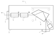
- FIG. 1 is a diagram showing a wavelength converter according to Embodiment 1 for carrying out the present invention.
- the wavelength conversion device 1 includes a second harmonic generation (SHG) crystal 4, a third harmonic generation (THG) crystal 5, and an antireflection coating, which will be described later, in the housing 2.
- the optical element support body 8 comprised from the prism 9 which is a non-optical element, the holder which supports this prism 9, etc., and the damper 6 are provided. Furthermore, the inside of the housing 2 is filled with clean air, oxygen gas, or inert gas, and is kept airtight. The configuration of the optical element support 8 will be described later.
- the wavelength converter 1 receives a fundamental laser beam L0 having a frequency ⁇ from a laser oscillator (not shown) and outputs a third harmonic laser beam L2.
- the fundamental laser beam L0 having the frequency ⁇ passes through the incident window 3 and enters the SHG crystal 4 when entering the wavelength conversion device 1.
- the SHG crystal 4 transmits part of the incident fundamental wave laser light L0 and converts the remaining part of the wavelength into the second harmonic laser light L1 that is the second harmonic of the double frequency.
- the first mixed laser beam M1 output from the SHG crystal 4 includes the fundamental laser beam L0 and the second harmonic laser beam L1.
- the first mixed laser beam M 1 is incident on the THG crystal 5.
- the THG crystal 5 transmits part of the incident first mixed laser light M1, and the remaining part of the fundamental laser light L0 and the second harmonic laser light L1 is three times the fundamental laser light. Wavelength-converted to a third harmonic laser beam L2, which is the third harmonic of the frequency of, and output.
- the output second mixed laser beam M2 includes a fundamental laser beam L0, a second harmonic laser beam L1, and a third harmonic laser beam L2.
- the laser beam M2 enters the prism 9, and is split into the fundamental laser beam L0, the second harmonic laser beam L1, and the third harmonic laser beam L2.
- the fundamental laser beam L0 and the second harmonic laser beam L1 are absorbed by the damper 6 and converted into thermal energy. Only the third harmonic laser beam L2 passes through the emission window 7 from the prism 9 and is output from the wavelength converter 1.
- FIG. 2 is a side view showing fixing of the prism 9 in the optical element support 8.
- the metal holder 11 is two flat plates each having four screw holes (not shown), and the two flat plates are a pair of pressing portions that press the prism 9.
- the prism 9 is an optical element having two parallel surfaces that do not contribute to spectroscopy. One of the two parallel surfaces of the prism 9 is in contact with one flat surface of the two flat plates of the metal holder 11. The remaining one of the two parallel surfaces of the prism 9 overlaps the remaining one flat surface of the two flat plates of the metal holder 11 with the indium sheet 10 interposed therebetween.
- the metal holder 11 supports the prism 9 with the indium sheet 10 sandwiched between one of two parallel surfaces of the prism 9.
- the metal sheet is melted to fix the flat plate of the metal holder 11 and the prism 9.
- the optical element support 8 includes a screw 12 that is a pressing member and a spring 13 that is also a pressing member.
- the screw 12 passes through a spring 13 through the shaft and is inserted into a screw hole of one metal holder 11.
- the screw 12 is inserted into a screw hole of another metal holder 11 with the prism 9 and the indium sheet 10 interposed therebetween, and the spring 13 is loaded. It is screwed to take.
- the prism 9 and the indium sheet 10 are pressed so as not to be displaced from the metal holder 11 by the load of the spring 13.
- the pressing portion of the metal holder 11 in contact with the indium sheet 10 is a flat plate, but it may not be flat and may have a surface with unevenness that is equal to or less than the thickness of the indium sheet. In this case, since the friction between the indium sheet 10 and the metal holder 11 becomes larger than the flat surface, the prism 9 can be fixed to the metal holder 11 more stably.
- the indium sheet 10 is disposed on only one of the two parallel surfaces of the prism 9, but may be disposed on both surfaces. However, if the indium sheet 10 is disposed on only one of the two parallel surfaces, the number of parts, the number of manufacturing steps, or the cost can be reduced.
- the wavelength conversion crystals 4 and 5 are deliquescent crystals, water remaining on the components in the casing is evaporated, so that the baking temperature in the above steps (2) and (7) ensures water.
- a temperature higher than the temperature at which it can be evaporated (100 ° C. under normal atmospheric pressure) is essential.
- each component, the optical element, and the metal sheet need to have a heat resistant temperature and a melting point higher than 100 ° C., and further need not be deformed under vacuum.
- the metal sheet needs to have a melting point higher than 100 ° C. However, in mass production, it must be melted at a temperature that is easy to heat ((4)). It is desirable that there is. (In this embodiment, indium is used and melting point is 156 ° C.)
- the housing 2 and the holder 11 are made of metal
- the clothing of the wiring is PTFE
- the metal sheet is indium. Indium is a pure metal, and the generation of outgas is equivalent to that of other metal parts during the heating of (4).
- each component, optical element, and metal sheet are not limited to the examples given here.
- the optical element supported by the metal holder 11 in the optical element support 8 is the prism 9, but may be used to support other optical elements such as a wavelength conversion element.
- the optical element By melting the metal sheet and fixing the optical element to the metal holder in this manner, the optical element is not displaced when an external force exceeding the frictional force of the surface pressed by transportation or the like is applied.
- the supporting optical element has a shape having only two parallel surfaces such as the prism 9, it can be fixed only from one direction of the two parallel surfaces.
- the pressure for pressing the optical element against the holder 11 can be reduced, so that stress is applied to the optical element as in the case of screwing and distortion occurs.
- the mode of the transmitted laser beam is not distorted. Further, as in the case where the optical element is fixed with an adhesive, the optical element can be reliably fixed without generating outgas.
- the optical element does not shift, the optical path of the laser beam does not shift, the optical element is not stressed, the laser beam mode is not distorted, and no outgas is generated, thereby preventing damage to the optical element and extending the life of the optical element be able to.
- N is an integer of 2 or more
- the incident / exiting of the prism is a Brewster angle with respect to the N-th harmonic
- the prism is made of a material having a low N-wave absorption factor.
Landscapes
- Physics & Mathematics (AREA)
- Nonlinear Science (AREA)
- General Physics & Mathematics (AREA)
- Optics & Photonics (AREA)
- Optical Modulation, Optical Deflection, Nonlinear Optics, Optical Demodulation, Optical Logic Elements (AREA)
Abstract
L'invention concerne un corps de soutien d'élément optique qui contient : un élément optique possédant deux surfaces parallèles; une monture qui comprend une paire de sections de support; une feuille de métal fondue qui est placée entre au moins une des surfaces des deux surfaces parallèle de l'élément optique et la section de support de la monture; et un élément de pressage qui applique une pression à la monture selon une direction maintenant fermement l'élément optique et la feuille de métal. Cet appareil de conversion de longueur d'onde est caractérisé en ce que : étant donnés le corps de soutien d'élément optique, un cristal de conversion de longueur d'onde qui transforme une longueur d'onde d'une lumière laser, et un boitier qui contient le corps de soutien d'élément optique et le cristal de conversion de longueur d'onde et dont l'intérieur dudit boitier est étanche à l'air; la longueur d'onde de la lumière laser est transformée au moyen du cristal de conversion de longueur d'onde; et une partie de la lumière laser est séparée de la lumière laser émise par le cristal de conversion de longueur d'onde au moyen de l'élément optique.
Priority Applications (1)
| Application Number | Priority Date | Filing Date | Title |
|---|---|---|---|
| PCT/JP2013/003378 WO2014192040A1 (fr) | 2013-05-29 | 2013-05-29 | Corps de soutien d'élément optique, appareil de conversion de longueur d'onde, et procédé de fabrication du corps de soutien d'élément optique. |
Applications Claiming Priority (1)
| Application Number | Priority Date | Filing Date | Title |
|---|---|---|---|
| PCT/JP2013/003378 WO2014192040A1 (fr) | 2013-05-29 | 2013-05-29 | Corps de soutien d'élément optique, appareil de conversion de longueur d'onde, et procédé de fabrication du corps de soutien d'élément optique. |
Publications (1)
| Publication Number | Publication Date |
|---|---|
| WO2014192040A1 true WO2014192040A1 (fr) | 2014-12-04 |
Family
ID=51988126
Family Applications (1)
| Application Number | Title | Priority Date | Filing Date |
|---|---|---|---|
| PCT/JP2013/003378 Ceased WO2014192040A1 (fr) | 2013-05-29 | 2013-05-29 | Corps de soutien d'élément optique, appareil de conversion de longueur d'onde, et procédé de fabrication du corps de soutien d'élément optique. |
Country Status (1)
| Country | Link |
|---|---|
| WO (1) | WO2014192040A1 (fr) |
Citations (9)
| Publication number | Priority date | Publication date | Assignee | Title |
|---|---|---|---|---|
| JPS61240210A (ja) * | 1985-03-29 | 1986-10-25 | ブリテイシユ・テレコミユニケーシヨンズ・パブリツク・リミテツド・カンパニ | 光学素子の取り付け方法 |
| JPH0572465A (ja) * | 1991-06-04 | 1993-03-26 | Canon Inc | 色分解プリズムの支持方法及びそれを用いた色分解光学系 |
| JPH09181376A (ja) * | 1995-12-26 | 1997-07-11 | Mitsubishi Heavy Ind Ltd | 固体レーザ励起用半導体レーザ及びその製造方法 |
| JPH11233858A (ja) * | 1998-02-10 | 1999-08-27 | Komatsu Ltd | エキシマレーザ、その光学部品の固定手段及びその固定方法 |
| WO2009093425A1 (fr) * | 2008-01-21 | 2009-07-30 | Nikon Corporation | Amplificateur optique à large bande, générateur d'impulsion optique, et instrument optique |
| JP2010507911A (ja) * | 2006-10-24 | 2010-03-11 | カール・ツァイス・エスエムティー・アーゲー | 光学素子をフレームに結合するための方法および装置 |
| WO2010150860A1 (fr) * | 2009-06-26 | 2010-12-29 | Agcセラミックス株式会社 | Dispositif et procédé de refroidissement pour parois de four réfractaire |
| JP2011215540A (ja) * | 2010-04-02 | 2011-10-27 | Mitsubishi Electric Corp | 波長変換装置及びこれを用いた波長変換レーザ装置 |
| WO2013035325A1 (fr) * | 2011-09-05 | 2013-03-14 | 日本電信電話株式会社 | Structure semi-conductrice de nitrure et son procédé de fabrication |
-
2013
- 2013-05-29 WO PCT/JP2013/003378 patent/WO2014192040A1/fr not_active Ceased
Patent Citations (9)
| Publication number | Priority date | Publication date | Assignee | Title |
|---|---|---|---|---|
| JPS61240210A (ja) * | 1985-03-29 | 1986-10-25 | ブリテイシユ・テレコミユニケーシヨンズ・パブリツク・リミテツド・カンパニ | 光学素子の取り付け方法 |
| JPH0572465A (ja) * | 1991-06-04 | 1993-03-26 | Canon Inc | 色分解プリズムの支持方法及びそれを用いた色分解光学系 |
| JPH09181376A (ja) * | 1995-12-26 | 1997-07-11 | Mitsubishi Heavy Ind Ltd | 固体レーザ励起用半導体レーザ及びその製造方法 |
| JPH11233858A (ja) * | 1998-02-10 | 1999-08-27 | Komatsu Ltd | エキシマレーザ、その光学部品の固定手段及びその固定方法 |
| JP2010507911A (ja) * | 2006-10-24 | 2010-03-11 | カール・ツァイス・エスエムティー・アーゲー | 光学素子をフレームに結合するための方法および装置 |
| WO2009093425A1 (fr) * | 2008-01-21 | 2009-07-30 | Nikon Corporation | Amplificateur optique à large bande, générateur d'impulsion optique, et instrument optique |
| WO2010150860A1 (fr) * | 2009-06-26 | 2010-12-29 | Agcセラミックス株式会社 | Dispositif et procédé de refroidissement pour parois de four réfractaire |
| JP2011215540A (ja) * | 2010-04-02 | 2011-10-27 | Mitsubishi Electric Corp | 波長変換装置及びこれを用いた波長変換レーザ装置 |
| WO2013035325A1 (fr) * | 2011-09-05 | 2013-03-14 | 日本電信電話株式会社 | Structure semi-conductrice de nitrure et son procédé de fabrication |
Similar Documents
| Publication | Publication Date | Title |
|---|---|---|
| JP5752417B2 (ja) | 光学結晶の環境制御用エンクロージャ | |
| JP5281922B2 (ja) | パルスレーザ装置 | |
| EP2259391A1 (fr) | Module de source lumineuse laser | |
| US10120262B2 (en) | Power-scalable nonlinear optical wavelength converter | |
| CN104937789A (zh) | 具有用于紫外发生的可更换模块的高功率固态激光器 | |
| JP6966042B2 (ja) | 2波長同時発振型赤外光パラメトリック発振装置 | |
| JP2629621B2 (ja) | 紫外レーザ装置 | |
| WO2014192040A1 (fr) | Corps de soutien d'élément optique, appareil de conversion de longueur d'onde, et procédé de fabrication du corps de soutien d'élément optique. | |
| Verpoort et al. | Novel unimorph deformable mirror for space applications | |
| CN110291439A (zh) | 高温光学分子抗污染吸杂系统 | |
| CN101803131B (zh) | 用于激光镜的热畸变补偿 | |
| CN115427878A (zh) | 二次谐波产生的晶体 | |
| JP2013097150A (ja) | エタロンフィルタ | |
| Mizushima et al. | Second harmonic generation with high conversion efficiency and wide temperature tolerance by multi-pass scheme | |
| JP2014029384A (ja) | 波長変換光学素子ホルダ、波長変換光学素子ホルダを備えたレーザ装置、レーザ装置を備えた露光装置及び検査装置 | |
| Möhle et al. | Highly stable piezoelectrically tunable optical cavities | |
| JP2012078474A (ja) | エタロンフィルタ | |
| Vanda et al. | Multiple pulse picosecond laser induced damage threshold on hybrid mirrors | |
| JP6880916B2 (ja) | 波長変換素子およびレーザ照射装置 | |
| JP2014174379A (ja) | 赤外固体レーザー発振装置 | |
| US11204536B1 (en) | Ultra-stable dual-mode operation optical crystal assembly for harmonic conversion | |
| US20250163612A1 (en) | Ovens for nonlinear optical crystals and method of use | |
| WO2015080832A1 (fr) | Système et procédé permettant de séparer un faisceau de signal et un ou plusieurs faisceaux d'entrée en utilisant un phénomène de déviation | |
| JP2011039246A (ja) | レーザ装置 | |
| JP5969193B2 (ja) | エタロンフィルタ |
Legal Events
| Date | Code | Title | Description |
|---|---|---|---|
| 121 | Ep: the epo has been informed by wipo that ep was designated in this application |
Ref document number: 13886117 Country of ref document: EP Kind code of ref document: A1 |
|
| NENP | Non-entry into the national phase |
Ref country code: DE |
|
| 122 | Ep: pct application non-entry in european phase |
Ref document number: 13886117 Country of ref document: EP Kind code of ref document: A1 |
|
| NENP | Non-entry into the national phase |
Ref country code: JP |