WO2014192122A1 - 車両用サスペンションシステム - Google Patents
車両用サスペンションシステム Download PDFInfo
- Publication number
- WO2014192122A1 WO2014192122A1 PCT/JP2013/065088 JP2013065088W WO2014192122A1 WO 2014192122 A1 WO2014192122 A1 WO 2014192122A1 JP 2013065088 W JP2013065088 W JP 2013065088W WO 2014192122 A1 WO2014192122 A1 WO 2014192122A1
- Authority
- WO
- WIPO (PCT)
- Prior art keywords
- target
- damping force
- speed
- vehicle
- sprung
- Prior art date
- Legal status (The legal status is an assumption and is not a legal conclusion. Google has not performed a legal analysis and makes no representation as to the accuracy of the status listed.)
- Ceased
Links
Images





Classifications
-
- B—PERFORMING OPERATIONS; TRANSPORTING
- B60—VEHICLES IN GENERAL
- B60G—VEHICLE SUSPENSION ARRANGEMENTS
- B60G17/00—Resilient suspensions having means for adjusting the spring or vibration-damper characteristics, for regulating the distance between a supporting surface and a sprung part of vehicle or for locking suspension during use to meet varying vehicular or surface conditions, e.g. due to speed or load
- B60G17/015—Resilient suspensions having means for adjusting the spring or vibration-damper characteristics, for regulating the distance between a supporting surface and a sprung part of vehicle or for locking suspension during use to meet varying vehicular or surface conditions, e.g. due to speed or load the regulating means comprising electric or electronic elements
- B60G17/016—Resilient suspensions having means for adjusting the spring or vibration-damper characteristics, for regulating the distance between a supporting surface and a sprung part of vehicle or for locking suspension during use to meet varying vehicular or surface conditions, e.g. due to speed or load the regulating means comprising electric or electronic elements characterised by their responsiveness, when the vehicle is travelling, to specific motion, a specific condition, or driver input
-
- B—PERFORMING OPERATIONS; TRANSPORTING
- B60—VEHICLES IN GENERAL
- B60G—VEHICLE SUSPENSION ARRANGEMENTS
- B60G17/00—Resilient suspensions having means for adjusting the spring or vibration-damper characteristics, for regulating the distance between a supporting surface and a sprung part of vehicle or for locking suspension during use to meet varying vehicular or surface conditions, e.g. due to speed or load
- B60G17/015—Resilient suspensions having means for adjusting the spring or vibration-damper characteristics, for regulating the distance between a supporting surface and a sprung part of vehicle or for locking suspension during use to meet varying vehicular or surface conditions, e.g. due to speed or load the regulating means comprising electric or electronic elements
- B60G17/016—Resilient suspensions having means for adjusting the spring or vibration-damper characteristics, for regulating the distance between a supporting surface and a sprung part of vehicle or for locking suspension during use to meet varying vehicular or surface conditions, e.g. due to speed or load the regulating means comprising electric or electronic elements characterised by their responsiveness, when the vehicle is travelling, to specific motion, a specific condition, or driver input
- B60G17/0162—Resilient suspensions having means for adjusting the spring or vibration-damper characteristics, for regulating the distance between a supporting surface and a sprung part of vehicle or for locking suspension during use to meet varying vehicular or surface conditions, e.g. due to speed or load the regulating means comprising electric or electronic elements characterised by their responsiveness, when the vehicle is travelling, to specific motion, a specific condition, or driver input mainly during a motion involving steering operation, e.g. cornering, overtaking
-
- B—PERFORMING OPERATIONS; TRANSPORTING
- B60—VEHICLES IN GENERAL
- B60G—VEHICLE SUSPENSION ARRANGEMENTS
- B60G17/00—Resilient suspensions having means for adjusting the spring or vibration-damper characteristics, for regulating the distance between a supporting surface and a sprung part of vehicle or for locking suspension during use to meet varying vehicular or surface conditions, e.g. due to speed or load
- B60G17/015—Resilient suspensions having means for adjusting the spring or vibration-damper characteristics, for regulating the distance between a supporting surface and a sprung part of vehicle or for locking suspension during use to meet varying vehicular or surface conditions, e.g. due to speed or load the regulating means comprising electric or electronic elements
- B60G17/016—Resilient suspensions having means for adjusting the spring or vibration-damper characteristics, for regulating the distance between a supporting surface and a sprung part of vehicle or for locking suspension during use to meet varying vehicular or surface conditions, e.g. due to speed or load the regulating means comprising electric or electronic elements characterised by their responsiveness, when the vehicle is travelling, to specific motion, a specific condition, or driver input
- B60G17/0164—Resilient suspensions having means for adjusting the spring or vibration-damper characteristics, for regulating the distance between a supporting surface and a sprung part of vehicle or for locking suspension during use to meet varying vehicular or surface conditions, e.g. due to speed or load the regulating means comprising electric or electronic elements characterised by their responsiveness, when the vehicle is travelling, to specific motion, a specific condition, or driver input mainly during accelerating or braking
-
- B—PERFORMING OPERATIONS; TRANSPORTING
- B60—VEHICLES IN GENERAL
- B60G—VEHICLE SUSPENSION ARRANGEMENTS
- B60G17/00—Resilient suspensions having means for adjusting the spring or vibration-damper characteristics, for regulating the distance between a supporting surface and a sprung part of vehicle or for locking suspension during use to meet varying vehicular or surface conditions, e.g. due to speed or load
- B60G17/015—Resilient suspensions having means for adjusting the spring or vibration-damper characteristics, for regulating the distance between a supporting surface and a sprung part of vehicle or for locking suspension during use to meet varying vehicular or surface conditions, e.g. due to speed or load the regulating means comprising electric or electronic elements
- B60G17/018—Resilient suspensions having means for adjusting the spring or vibration-damper characteristics, for regulating the distance between a supporting surface and a sprung part of vehicle or for locking suspension during use to meet varying vehicular or surface conditions, e.g. due to speed or load the regulating means comprising electric or electronic elements characterised by the use of a specific signal treatment or control method
-
- B—PERFORMING OPERATIONS; TRANSPORTING
- B60—VEHICLES IN GENERAL
- B60G—VEHICLE SUSPENSION ARRANGEMENTS
- B60G17/00—Resilient suspensions having means for adjusting the spring or vibration-damper characteristics, for regulating the distance between a supporting surface and a sprung part of vehicle or for locking suspension during use to meet varying vehicular or surface conditions, e.g. due to speed or load
- B60G17/06—Characteristics of dampers, e.g. mechanical dampers
- B60G17/08—Characteristics of fluid dampers
-
- B—PERFORMING OPERATIONS; TRANSPORTING
- B60—VEHICLES IN GENERAL
- B60G—VEHICLE SUSPENSION ARRANGEMENTS
- B60G2206/00—Indexing codes related to the manufacturing of suspensions: constructional features, the materials used, procedures or tools
- B60G2206/01—Constructional features of suspension elements, e.g. arms, dampers, springs
- B60G2206/40—Constructional features of dampers and/or springs
- B60G2206/41—Dampers
-
- B—PERFORMING OPERATIONS; TRANSPORTING
- B60—VEHICLES IN GENERAL
- B60G—VEHICLE SUSPENSION ARRANGEMENTS
- B60G2400/00—Indexing codes relating to detected, measured or calculated conditions or factors
- B60G2400/10—Acceleration; Deceleration
- B60G2400/102—Acceleration; Deceleration vertical
-
- B—PERFORMING OPERATIONS; TRANSPORTING
- B60—VEHICLES IN GENERAL
- B60G—VEHICLE SUSPENSION ARRANGEMENTS
- B60G2400/00—Indexing codes relating to detected, measured or calculated conditions or factors
- B60G2400/10—Acceleration; Deceleration
- B60G2400/104—Acceleration; Deceleration lateral or transversal with regard to vehicle
-
- B—PERFORMING OPERATIONS; TRANSPORTING
- B60—VEHICLES IN GENERAL
- B60G—VEHICLE SUSPENSION ARRANGEMENTS
- B60G2400/00—Indexing codes relating to detected, measured or calculated conditions or factors
- B60G2400/10—Acceleration; Deceleration
- B60G2400/106—Acceleration; Deceleration longitudinal with regard to vehicle, e.g. braking
-
- B—PERFORMING OPERATIONS; TRANSPORTING
- B60—VEHICLES IN GENERAL
- B60G—VEHICLE SUSPENSION ARRANGEMENTS
- B60G2400/00—Indexing codes relating to detected, measured or calculated conditions or factors
- B60G2400/20—Speed
- B60G2400/204—Vehicle speed
-
- B—PERFORMING OPERATIONS; TRANSPORTING
- B60—VEHICLES IN GENERAL
- B60G—VEHICLE SUSPENSION ARRANGEMENTS
- B60G2400/00—Indexing codes relating to detected, measured or calculated conditions or factors
- B60G2400/20—Speed
- B60G2400/204—Vehicle speed
- B60G2400/2042—Lateral speed
-
- B—PERFORMING OPERATIONS; TRANSPORTING
- B60—VEHICLES IN GENERAL
- B60G—VEHICLE SUSPENSION ARRANGEMENTS
- B60G2400/00—Indexing codes relating to detected, measured or calculated conditions or factors
- B60G2400/25—Stroke; Height; Displacement
- B60G2400/252—Stroke; Height; Displacement vertical
-
- B—PERFORMING OPERATIONS; TRANSPORTING
- B60—VEHICLES IN GENERAL
- B60G—VEHICLE SUSPENSION ARRANGEMENTS
- B60G2400/00—Indexing codes relating to detected, measured or calculated conditions or factors
- B60G2400/30—Propulsion unit conditions
- B60G2400/34—Accelerator pedal position
-
- B—PERFORMING OPERATIONS; TRANSPORTING
- B60—VEHICLES IN GENERAL
- B60G—VEHICLE SUSPENSION ARRANGEMENTS
- B60G2400/00—Indexing codes relating to detected, measured or calculated conditions or factors
- B60G2400/30—Propulsion unit conditions
- B60G2400/39—Brake pedal position
-
- B—PERFORMING OPERATIONS; TRANSPORTING
- B60—VEHICLES IN GENERAL
- B60G—VEHICLE SUSPENSION ARRANGEMENTS
- B60G2400/00—Indexing codes relating to detected, measured or calculated conditions or factors
- B60G2400/40—Steering conditions
- B60G2400/41—Steering angle
-
- B—PERFORMING OPERATIONS; TRANSPORTING
- B60—VEHICLES IN GENERAL
- B60G—VEHICLE SUSPENSION ARRANGEMENTS
- B60G2500/00—Indexing codes relating to the regulated action or device
- B60G2500/10—Damping action or damper
- B60G2500/104—Damping action or damper continuous
-
- B—PERFORMING OPERATIONS; TRANSPORTING
- B60—VEHICLES IN GENERAL
- B60G—VEHICLE SUSPENSION ARRANGEMENTS
- B60G2600/00—Indexing codes relating to particular elements, systems or processes used on suspension systems or suspension control systems
- B60G2600/18—Automatic control means
- B60G2600/184—Semi-Active control means
-
- B—PERFORMING OPERATIONS; TRANSPORTING
- B60—VEHICLES IN GENERAL
- B60G—VEHICLE SUSPENSION ARRANGEMENTS
- B60G2600/00—Indexing codes relating to particular elements, systems or processes used on suspension systems or suspension control systems
- B60G2600/22—Magnetic elements
- B60G2600/26—Electromagnets; Solenoids
-
- B—PERFORMING OPERATIONS; TRANSPORTING
- B60—VEHICLES IN GENERAL
- B60G—VEHICLE SUSPENSION ARRANGEMENTS
- B60G2600/00—Indexing codes relating to particular elements, systems or processes used on suspension systems or suspension control systems
- B60G2600/82—Indexing codes relating to particular elements, systems or processes used on suspension systems or suspension control systems duty rate function
-
- B—PERFORMING OPERATIONS; TRANSPORTING
- B60—VEHICLES IN GENERAL
- B60G—VEHICLE SUSPENSION ARRANGEMENTS
- B60G2800/00—Indexing codes relating to the type of movement or to the condition of the vehicle and to the end result to be achieved by the control action
- B60G2800/01—Attitude or posture control
- B60G2800/012—Rolling condition
-
- B—PERFORMING OPERATIONS; TRANSPORTING
- B60—VEHICLES IN GENERAL
- B60G—VEHICLE SUSPENSION ARRANGEMENTS
- B60G2800/00—Indexing codes relating to the type of movement or to the condition of the vehicle and to the end result to be achieved by the control action
- B60G2800/01—Attitude or posture control
- B60G2800/014—Pitch; Nose dive
-
- B—PERFORMING OPERATIONS; TRANSPORTING
- B60—VEHICLES IN GENERAL
- B60G—VEHICLE SUSPENSION ARRANGEMENTS
- B60G2800/00—Indexing codes relating to the type of movement or to the condition of the vehicle and to the end result to be achieved by the control action
- B60G2800/90—System Controller type
- B60G2800/91—Suspension Control
Definitions
- the present invention relates to a vehicle suspension system including a shock absorber that can generate a changeable magnitude of a damping force with respect to a relative motion between an upper part and an unsprung part.
- the following patent document has a damping force changing mechanism that changes the magnitude of the damping force relative to the relative motion between the sprung portion and the unsprung portion, and the damping force for the relative motion between the sprung portion and the unsprung portion can be changed
- a suspension system for a vehicle including a shock absorber is described.
- a method of controlling the damping force changing mechanism and controlling the damping force there are various methods as described in the following patent document, for example. JP-A-3-42320 WO / 2012/032655 publication Japanese Patent Laid-Open No. 5-124413
- the damping force changing mechanism is controlled for the purpose of both riding comfort and steering stability.
- viewpoints other than the ride comfort and steering stability and it is possible to improve the practicality of the suspension system by paying attention to such viewpoints and making various improvements.
- This invention is made
- a vehicle suspension system determines a target sprung speed, which is a target sprung speed, based on a vehicle operation input by a driver, and the sprung speed is The damping force is controlled so as to achieve the target sprung speed.
- the behavior of the vehicle body is controlled to achieve the target sprung speed determined based on the vehicle operation input by the driver, so that the vehicle body can be operated by the driver. Takes corresponding behavior.
- the suspension system of the present invention has the advantage that it can give the driver an appropriate feeling of operation, and thus has high practicality.
- each of items (1) to (11) corresponds to each of claims 1 to 11.
- a damping force changing mechanism is provided between the spring upper part and the springed part to change the magnitude of the damping force, and the damping force for the relative movement between the spring upper part and the spring lower part is changed.
- a suspension system for a vehicle comprising: a shock absorber that can be generated; and (b) a control device that controls the damping force generated by the shock absorber by controlling the damping force changing mechanism,
- the control device is A target sprung speed determination unit that determines a target sprung speed, which is a target sprung speed, based on a vehicle operation input by the driver, so that the sprung speed becomes the target sprung speed.
- a suspension system for a vehicle configured to control the damping force.
- the behavior of the vehicle body is controlled so that the target sprung speed is determined based on the vehicle operation input by the driver. Therefore, according to the suspension system of this section, the vehicle body behaves in accordance with the driver's operation, so that the discomfort given to the driver due to the discrepancy between the driver's operation and the vehicle body behavior is reduced. Thus, it is possible to give the driver an appropriate feeling of operation.
- the suspension system described in this section can be configured to determine the target sprung speed based on, for example, steering operation, accelerator operation, and brake operation. As a result, the roll motion of the vehicle body can be made in response to the steering operation, and the pitch motion of the vehicle body can be made in response to the accelerator operation or the brake operation.
- the magnitude of the damping force in the present specification may mean a difference in damping force generation characteristics, specifically, the magnitude of the damping coefficient, and the above-mentioned “damping force changing mechanism”.
- the change of the damping force by means of a change in the damping force generation characteristic, specifically, the change of the damping coefficient may be meant.
- the mode described in this section is a mode in which the target sprung speed is determined using at least a steering operation as a driver's operation input. According to the aspect of this section, the roll motion of the vehicle body can be made according to the steering operation.
- the target sprung speed determination unit Based on the operation speed of the steering operation and the vehicle speed, a target roll speed that is a target of the speed for rolling the vehicle body is determined, and the target sprung speed is determined based on the target roll speed (2) The vehicle suspension system according to item.
- the target sprung speed determination unit The vehicle suspension system according to item (3), wherein the target roll speed is determined by a product of a gain determined based on a vehicle speed and an operation speed of a steering operation.
- the modes described in the above two sections are modes in which a method for determining the target sprung speed based on the steering operation is embodied, and the shock absorber provided corresponding to each wheel from the target roll speed.
- the target sprung speed is determined.
- the target sprung speed determination unit is configured to determine the target sprung speed based on an operation input of the vehicle by the driver and information on motion control executed in the vehicle ( The vehicle suspension system according to any one of items 1) to (4).
- the vehicle is moved by control separately from the operation input by the driver.
- control for adjusting the direction of the vehicle to suppress the side slip of the vehicle and control for adjusting the speed of the vehicle so as to travel following the preceding vehicle are performed.
- the aspect described in this section is configured to determine the target sprung speed using information related to the control as described above in addition to the driver's operation input.
- the uncomfortable feeling given to the driver due to the discrepancy between the running state of the vehicle and the behavior of the vehicle body is reduced. It is possible.
- a vehicle on which the vehicle suspension system is mounted is As the motion control executed in the vehicle, the vehicle body turning control, which is a control for changing the direction of the vehicle body, is performed separately from the change of the vehicle body direction by the driver's steering operation.
- the target sprung speed determination unit is The vehicle suspension system according to item (5), configured to determine the target sprung speed based on a steering operation performed by a driver and information on the vehicle body turning control.
- the mode described in this section is a mode in which vehicle motion control is limited.
- the “vehicle turning control” is, for example, control for adjusting the direction of the vehicle body by adjusting the acceleration / deceleration of each wheel so as to suppress the side slip of the vehicle.
- an amount for changing the direction of the vehicle body by the steering operation is added to the amount for changing the direction of the vehicle body by the steering operation. Therefore, for example, the aspect described in this section is based on the amount of change in the direction of the vehicle body by adding the amount of change in the direction of the vehicle body by the steering operation and the amount of change in the direction of the vehicle body by the vehicle body turning control. It can be set as the structure which determines the sprung speed.
- the amount by which the direction of the vehicle body is changed by the vehicle body turning control is converted into the operation amount of the steering operation, and the target sprung speed is determined based on the value obtained by correcting the actual steering operation amount by the converted value. It can be set as a simple structure. Note that the amount by which the direction of the vehicle body is changed by the vehicle body turning control can be determined based on, for example, a slip angle or a yaw rate during turning.
- the control device A reference damping force determination unit that determines a reference damping force that is a damping force having a magnitude corresponding to a predetermined control rule and serves as a reference for determining a target of the damping force generated by the shock absorber; , A target damping force determination unit that determines a target damping force that is a target of the damping force generated by the shock absorber by correcting the reference damping force based on the target sprung speed.
- the vehicle suspension system according to any one of (6).
- the mode described in this section is a mode configured to correct the damping force to be generated in the control by increasing / decreasing based on the target sprung speed while executing the basic damping force control. is there. Since the damping force generated by the shock absorber is for the relative motion between the sprung portion and the unsprung portion, for example, based on the direction of the relative motion between the sprung portion and the unsprung portion and the direction of the target sprung speed, The reference damping force can be corrected so as to increase or decrease. Further, as will be described in detail later, it is possible to adopt a mode in which the target sprung speed is determined in consideration of the actual sprung speed in addition to the target sprung speed.
- the control device includes a sprung speed acquisition unit that acquires an actual sprung speed that is an actual sprung speed.
- the target damping force determination unit is configured to correct the reference damping force based on a sprung speed deviation that is a difference between the actual sprung speed and the target sprung speed. Vehicle suspension system.
- the aspect described in this section is further configured to correct the damping force in consideration of the actual sprung speed. According to the aspect of this section, the correction of the reference damping force becomes more appropriate, and an appropriate operational feeling can be given to the driver.
- the target damping force determination unit (i) When the sprung speed deviation is positive and the sprung part and the sprung part are moving away from each other, or when the sprung speed deviation is negative and the sprung part and the sprung part are close to each other. (Ii) the sprung speed deviation is negative and the sprung portion and the unsprung portion are moved away from each other. Or when the sprung speed deviation is positive and the sprung portion and the unsprung portion are moving toward each other, the damping force is increased with respect to the reference damping force.
- the vehicle suspension system according to item (8).
- the mode described in this section is a mode in which a method for determining whether to increase or decrease the reference damping force is realized. Since the damping force generated by the shock absorber acts on the relative motion between the sprung portion and the unsprung portion, for example, even if the direction in which the sprung portion is to be operated is upward, It is desirable to increase or decrease the reference damping force depending on the direction of the relative motion.
- the mode described in this section is a mode in which the increase / decrease from the reference damping force is determined based on the positive / negative of the sprung speed deviation and the direction of relative movement between the sprung portion and the unsprung portion.
- the target damping force determination unit The vehicle suspension system according to (8) or (9), wherein the amount of correction from the reference damping force is increased as the sprung speed deviation increases.
- the mode described in this section is a mode in which the magnitude of the correction amount from the reference damping force is determined.
- the damping force for realizing the behavior of the vehicle body according to the driver's operation input can be set to an appropriate magnitude.
- the target damping force determination unit The vehicle suspension system according to any one of (7) to (9), configured to remove a component having a frequency lower than a set frequency of the sprung speed deviation.
- the target sprung speed can be made more appropriate.
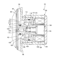
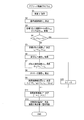
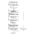
- FIG. 1 It is a figure showing typically a suspension system for vehicles as an example of a claimable invention. It is sectional drawing which shows the hydraulic shock absorber shown in FIG. It is sectional drawing which shows the damping force generator with which the hydraulic-type shock absorber shown in FIG. 2 is provided. It is a graph which shows typically the relation between a standard damping coefficient and vehicle speed. It is a control block diagram of control performed in the suspension system for vehicles as an example of claimable invention. It is a flowchart which shows the absorber control program performed by the control apparatus shown in FIG. It is a flowchart which shows the roll component determination program performed by the control apparatus shown in FIG. It is a flowchart which shows the pitch component determination program performed by the control apparatus shown in FIG.
- FIG. 1 schematically shows a vehicle suspension system 10 that is an embodiment of the claimable invention.
- the suspension system 10 includes four independent suspension type suspension devices 12 corresponding to the front, rear, left, and right wheels 12.
- Each of the suspension devices 12 holds a wheel 14 and constitutes a part of an unsprung portion.
- the suspension lower arm is disposed between the suspension lower arm and the mount portion which is provided on the vehicle body and constitutes a part of the upper portion of the spring.
- Each of the suspension devices 12 includes a coil spring 16 as a suspension spring and a hydraulic shock absorber 20, which are arranged in parallel with each other between the lower arm and the mount portion.
- the wheel 14 and the suspension device 12 are generic names, and when it is necessary to clarify which of the four wheels 14 corresponds, as shown in the figure, as a subscript indicating the wheel position, In some cases, FL, FR, RL, and RR are attached to the front wheel, the right front wheel, the left rear wheel, and the right rear wheel.
- the hydraulic shock absorber 20 includes a cylinder 22 and a damping force generator 24 as main components.
- the cylinder 22 includes a housing 30, a piston 32 movably arranged in the vertical direction inside the housing 30, one end (lower end) connected to the piston 32, and the other end (upper end) at the housing. And a rod 34 extending upward from 30.
- a connecting member 26 is attached to the lower end of the housing 30, and the housing 30 is a rod in which a male screw is formed on a lower part of the vehicle (for example, a suspension lower arm, a steering knuckle, etc.) via the connecting member 36.
- the upper end of 34 is connected to the sprung portion of the vehicle (for example, a mount provided on the vehicle body) using the male screw.
- the cylinder 22 is disposed so as to connect the sprung portion and the unsprung portion of the vehicle.
- the cylinder 22 expands and contracts with the relative movement in the vertical direction between the spring top and the spring bottom, that is, with separation and approach. More specifically, when the spring upper part and the unsprung part move relative to each other (hereinafter sometimes referred to as “rebound operation” or “rebound operation”), the extension moves and moves relative to each other in the approaching direction. (Hereinafter, sometimes referred to as “bounding operation” or “bounding”).
- the piston 32 is movable in sliding contact with the inside of the housing 30, and two liquid chambers 40 and 42 filled with the working fluid are defined in the housing 30 by the piston 32. More specifically, a rod side chamber 40 that is positioned above the piston 32 and through which the rod 34 penetrates, and an anti-rod side chamber 42 that is positioned below the piston 32 are partitioned.
- the volumes of the two liquid chambers 40 and 42 change with the expansion and contraction of the cylinder 22, that is, with the relative movement between the spring top and the spring bottom. Specifically, during the rebound operation, the volume of the rod side chamber 40 decreases and the volume of the non-rod side chamber 42 increases. On the other hand, during the bounding operation, the volume of the rod side chamber 40 increases and the volume of the non-rod side chamber 42 decreases.
- the housing 30 generally has a double structure, and has a bottomed main tube 46 and an outer tube 48 attached to the outer peripheral side of the main tube 46.
- the periphery of the rod side chamber 40 and the anti-rod side chamber 42 is partitioned by the inner peripheral surface of the main tube 46, and the hydraulic fluid is separated between the outer peripheral surface of the main tube 46 and the inner peripheral surface of the outer tube 48.
- a buffer chamber 50 also referred to as “reservoir” or “reservoir chamber” 50 is defined. Due to the presence of the rod 34, the total volume of the rod side chamber 40 and the anti-rod side chamber 42 increases when rebounding and decreases when bounding.
- the buffer chamber 50 is a liquid chamber provided to allow a change in the total volume in a state where the rod side chamber 40 and the anti-rod side chamber 42 are filled with the working fluid.
- a partition member 52 that partitions the bottom of the anti-rod side chamber 42 is provided at the inner bottom of the main tube 46, and a bottom liquid passage 54 is provided between the partition member 52 and the bottom wall of the main tube 46. Is formed.
- An inter tube 60 is disposed between the main tube 46 and the outer tube 48 so as to surround the main tube 46.
- the inner periphery of the buffer chamber 50 is partly defined by the outer peripheral surface of the intertube 60 in detail.
- a relatively long annular liquid passage 62 is defined between the inner peripheral surface of the intertube 60 and the outer peripheral surface of the main tube 46.
- a circulation hole 64 is provided for the circulation of the working fluid between the liquid passage 62 and the rod side chamber 40. Further, a bottom portion circulation hole 66 is provided in a portion near the lower end of the main tube 46 for the circulation of the working fluid between the buffer chamber 50 and the bottom portion liquid passage 54.
- an outlet 70 is provided that allows the hydraulic fluid to flow out from the liquid passage 62 to the damping force generator 24 described above.
- the outer tube 48 is provided with an inflow port 74 that is coaxially disposed with the outflow port 70 and allows inflow of hydraulic fluid from the damping force generator 24 to the buffer chamber 50, which will be described in detail later. Yes.
- the partition member 52 described above includes a liquid passage connecting the bottom liquid passage 54 and the anti-rod side chamber, and an anti-rod side chamber check valve 80 disposed in the liquid passage.
- the anti-rod side chamber check valve 80 allows the flow of hydraulic fluid from the buffer chamber 50 to the anti-rod side chamber 42 via the bottom liquid passage 54 with little resistance, while the bottom liquid passage 54 from the anti-rod side chamber 42. This is a check valve having a function of prohibiting the outflow of hydraulic fluid into the buffer chamber 50 via the.
- the piston 32 has a pair of liquid passages that connect the rod side chamber 40 and the anti-rod side chamber 42, and a pair of check valves 82 and 84 that are respectively provided in the pair of liquid passages.
- One check valve 82 has a function of allowing hydraulic fluid to pass from the rod side chamber 40 to the anti-rod side chamber 42 and prohibiting passage of hydraulic fluid from the anti-rod side chamber 42 to the rod side chamber 40.
- the other check valve 84 has a function of allowing the hydraulic fluid to pass from the anti-rod side chamber 42 to the rod-side chamber 40 and prohibiting the hydraulic fluid from passing from the rod-side chamber 40 to the anti-rod side chamber 42.
- the check valve 82 allows the hydraulic fluid to pass only when the pressure of the hydraulic fluid in the rod side chamber 40 is considerably larger than the pressure of the hydraulic fluid in the anti-rod side chamber 42, Under normal conditions, the hydraulic fluid is not substantially passed from the rod side chamber 40 of the piston 32 to the non-rod side chamber 42.
- the damping force generator 24 is disposed so as to cover the outlet 70 and the inlet 74, and flows out of the rod side chamber 40 and is buffered via the liquid passage 62. It has a function of allowing the hydraulic fluid flowing into the chamber 50 to pass therethrough and giving resistance to the flow of the hydraulic fluid.
- the check valve 84 of the piston 32 is moved from the rod side chamber 40 of the cylinder 22 to the rod side chamber 42.
- the working fluid flows in through the liquid passage in which is disposed. Since the amount of the hydraulic fluid flowing into the rod side chamber 40 is larger than the volume that increases with the operation of the piston 32 of the rod side chamber 40, the rod side chamber 40 passes through the circulation hole 64 and the liquid passage 62 and The hydraulic fluid flows through the damping force generator 24 into the buffer chamber 50.
- a damping force for the contraction of the cylinder 22, that is, a damping force for the bounce operation is generated by the resistance given to the flow of the hydraulic fluid passing through the damping force generator 24.
- the hydraulic fluid flows out from the rod side chamber 40 of the cylinder 22 through the flow hole 64 and the liquid passage 62 and through the damping force generator 24 to the buffer chamber 50 in the same manner as during the bounce operation.
- the damping force for the extension of the cylinder 22, that is, the damping force for the rebound operation is generated by the resistance given to the flow of the hydraulic fluid passing through the damping force generator 24.
- the anti-rod side chamber 42 of the cylinder 22 is operated from the buffer chamber 50 through the bottom flow hole 64, the bottom liquid passage 54, and the anti-rod side chamber check valve 80, as shown by the broken arrow in FIG. Liquid flows in.
- the damping force with respect to the bounce operation and the rebound operation has a magnitude corresponding to the resistance given by the damping force generator 24 to the flow of the hydraulic fluid, and the damping force increases as the resistance increases.
- the damping force generator 24 is an electromagnetic valve, as will be described in detail later, and the magnitude of the resistance provided by the damping force generator 24 depends on the magnitude of the supplied current. . That is, the rebound operation and the damping force for the bounce operation depend on the magnitude of the supplied current.
- the damping force generator 24 is mainly composed of a valve mechanism 98 for imparting resistance to the hydraulic fluid that passes through the damping force generator 24. 102, a valve body (also referred to as “valve movable body”) 104 accommodated in the valve housing 102, a solenoid 106, and a spring 108 which is a compression coil spring.
- the solenoid 106 has a function of applying an urging force in a direction that limits the flow path area to the valve body 104 that constitutes the valve mechanism 98, and the spring 108 applies an urging force in a direction that maximizes the flow path area. Has the function to give.
- the valve housing 102 includes a horizontal hole 114 extending along the axis of the damping force generator 24, a vertical hole 116 communicating with the horizontal hole 114, and a liquid passage 62 side (the left side in FIG. 3) from the opening of the vertical hole 116.
- the through-hole 120 is provided in the flange 118 formed in (1).
- the outer periphery of the tip (left end in FIG. 3) of the valve housing 102 is fitted to a sleeve 122 provided at the outlet 70 of the intertube 60.
- the left end opening of the horizontal hole 114 is exposed to the liquid passage 62 formed between the main tube 46 and the inter tube 60, and the through hole 120 is exposed to the buffer chamber 50.
- the flow path 100 is formed by the hole 114, the vertical hole 116, and the through hole 120.
- valve housing 102 is provided with a small inner diameter portion 124 in the middle of the horizontal hole 114, more specifically, on the liquid passage 62 side (left side in FIG. 3) of the vertical hole 116.
- An annular valve seat 126 is formed by the inner edge.
- the solenoid 106 includes a coil 130, a solenoid bobbin 132 that holds the coil 130, and a bottomed cylindrical case 134 that includes the coil 130 and the solenoid bobbin 132.
- the case 134 is screwed into a cylinder 136 attached to the inlet 74 of the outer tube 48.
- the valve body 104 includes a large diameter portion 170 slidably contacting the inner periphery of the right end in FIG. 3 of the valve housing 102, a small diameter portion 172 extending from the left end of the large diameter portion 170 and facing the vertical hole 116 of the valve housing 102, and a small diameter portion 172 and a poppet type valve head 174 formed at the left end.
- the valve body 104 can open and close the flow path 100 when the valve head 174 is seated on and off the valve seat 126.
- the valve body 104 includes a core portion 176 that extends from the right end of the large-diameter portion 170 and serves as a main body that generates a force that attracts the valve body 104 when excited.
- a stepped shape is formed between the core portion 176 and the large-diameter portion 170, and the stepped portion is an end portion formed in the stepped shape of the valve housing 102 (the right end in FIG. 3). ).
- the above-described spring 108 is interposed between the left end of the large-diameter portion 170 in the valve body 104 and the right end of the small-inner diameter portion 120 of the valve housing 102, and the spring 108 is connected to the valve body 104 and the valve body 104.
- the biasing force in the direction away from the seat 122 that is, the biasing force in the direction of increasing the flow channel area of the flow channel 100 is applied.
- the magnetic path is formed so as to pass through the case 134, the cylinder 136, the valve housing 102, and the core portion 176 of the valve body 14.
- the valve body 104 is moved in a direction in which the core portion 176 approaches the valve housing 102, in other words, in a direction in which the valve head 174 approaches the valve seat 126.
- the energizing force that occurs is generated.
- the damping force generator 24 it can be considered that when a current is supplied to the solenoid 106, that is, when a current is supplied to itself, a liquid passage that communicates the flow path 100 is formed.
- resistance is provided to the flow of hydraulic fluid passing through the damping force generator 24.
- the above-described valve mechanism 98 is disposed in the flow path 100, and resistance is given to the flow of hydraulic fluid passing between the valve seat 126 and the valve body 104 constituting the valve mechanism 98. It is done. The magnitude of this resistance depends on the size of the gap between the valve seat 126 and the valve body 104, that is, the degree of valve opening of the valve mechanism 98.
- the urging force that the solenoid 104 applies to the valve body 104 depends on the magnitude of the current supplied to the solenoid 104. Due to the structure of the valve mechanism 98 described above, the degree of valve opening increases as the current increases. Lower. That is, it becomes difficult to open the valve. Therefore, as the supplied current increases, the resistance given to the flow of the hydraulic fluid passing through the liquid passage increases.
- the damping force generator 24 is configured to generate a damping force with respect to the expansion and contraction of the cylinder 22, and the damping force increases as the supplied current increases.
- the coefficient increases as the current increases. That is, the damping force generator 24 changes the resistance to the flow of the hydraulic fluid passing through the liquid passage according to the magnitude of the current supplied to itself, so that the magnitude corresponding to the magnitude of the current is increased. It is configured to generate a damping force. That is, each of the shock absorbers 20 has a damping force changing mechanism that changes the magnitude of the damping force, so that the damping force for the relative motion between the sprung portion and the unsprung portion can be generated in a changeable manner. is there.
- the shock absorber 20 is controlled by a suspension electronic control unit 200 (hereinafter also referred to as “ECU 200”) as a control device.
- the ECU 200 is mainly configured by a computer including a CPU, a ROM, a RAM, and the like.
- the ECU 200 is connected to a driving circuit 202 provided corresponding to the damping force generator 24 of each shock absorber 20 and capable of adjusting the current to the corresponding damping force generator 24.
- the drive circuits 202 are connected to a battery [BAT] 204, and a current is supplied from the battery 204 to the damping force generator 24 of each shock absorber 20.
- the vehicle includes a vehicle speed sensor [V] 210 for detecting a vehicle travel speed (hereinafter sometimes abbreviated as “vehicle speed”), an operation angle sensor [ ⁇ ] 212 for detecting an operation angle of the steering wheel, A longitudinal acceleration sensor [Gx] 214 that detects actual longitudinal acceleration that is actually generated longitudinal acceleration, a lateral acceleration sensor [Gy] 216 that detects actual lateral acceleration that is actually generated in the vehicle body, and each wheel 12.
- V vehicle speed sensor
- ⁇ operation angle sensor
- a longitudinal acceleration sensor [Gx] 214 that detects actual longitudinal acceleration that is actually generated longitudinal acceleration
- a lateral acceleration sensor [Gy] 216 that detects actual lateral acceleration that is actually generated in the vehicle body, and each wheel 12.
- sprung vertical acceleration sensors [Gz] 218 for detecting the vertical acceleration (vertical acceleration) of each spring upper part of the vehicle body corresponding to, and four stroke sensors for detecting the stroke of the cylinder 22 of the shock absorber 20 on each wheel 12 [ St] 220, an accelerator pedal force sensor [Ac] 222 for detecting the pedal force of the accelerator pedal, a brake pedal for detecting the pedal force of the brake pedal Sensor [Br] 224 or the like is provided with, which are connected to ECU200 computer.
- the ECU 200 controls the shock absorber based on signals from these sensors.
- the character [] is a symbol used when the sensor or the like is shown in the drawing.
- the ROM included in the computer of the ECU 200 stores a program related to the control of the shock absorber 20, various data, and the like.
- FIG. 5 shows a block diagram of control in the suspension system 10.
- the control of the shock absorber at normal time is to suppress the vibration generated in the vehicle by generating a damping force as a damping coefficient corresponding to the vehicle speed.
- the supply current is controlled so that the damping force (damping coefficient) increases as the vehicle speed increases.
- the map data shown in FIG. 4 is stored in the RAM of the ECU 200. With reference to the map data, the damping coefficient ⁇ e is determined with respect to the vehicle speed V detected by the vehicle speed sensor 210. It is determined.
- the supply current I to the damping force generator 24 is controlled so that the determined damping coefficient ⁇ e is obtained.
- the damping coefficient ⁇ e determined according to the vehicle speed V is a reference damping coefficient that serves as a reference when determining the target damping coefficient when there is an operation input.
- the present steering system 10 corrects the reference damping coefficient when a steering operation is input, more specifically, when a steering operation input exceeding the set operation angle ⁇ 0 occurs.
- the process to do is performed.
- the target roll speed ⁇ ′ roll angle: ⁇
- the target roll speed ⁇ ′ is set so that the roll of the vehicle body corresponds to the steering operation. Is to decide.
- K Gy Steady lateral acceleration gain
- K f Front equivalent cornering power
- K r Rear equivalent cornering power
- l Hall base
- l f Distance between front axis center of gravity
- l r Distance between rear axis center of gravity
- m vehicle mass.
- Equation of motion around the roll axis can be expressed by the following equation.
- G s ⁇ h s m s a y + h s ⁇ m s g
- G s roll rigidity
- h s roll arm length
- m s sprung mass.
- ⁇ ⁇ h s m s K Gy / (G s ⁇ h s m s g) ⁇ ⁇
- ⁇ ′ ⁇ h s m s K Gy / (G s ⁇ h s m s g) ⁇ ⁇ ′
- ⁇ ′ is the operation speed.
- the target roll speed ⁇ ′ is determined based on the steady lateral acceleration gain K Gy calculated from the vehicle speed V and the steering operation speed ⁇ ′. Then, based on the determined target roll speed ⁇ ′, the roll component v sR of the sprung target sprung speed v s * corresponding to each wheel 12 is determined.
- a vehicle equipped with the steering system 10 has a so-called VSC as control for changing the direction of the vehicle body by controlling the driving and braking of each wheel in order to suppress the side slip of the vehicle, that is, as vehicle body turning control. Control is executed, and the direction of the vehicle body may be changed by the control separately from the change of the vehicle body direction by the driver's steering operation. Therefore, in the present steering system 10, the roll component v sR of the target sprung speed is determined in consideration of the change in the direction of the vehicle body by the VSC control.
- the steering system 10 calculates the reference damping coefficient when an accelerator operation or a brake operation is input, more specifically, when an operation input exceeds a set pedaling force. Correction processing is performed.
- a target pitch speed ⁇ ′ is set so that the pitch of the vehicle body corresponds to the accelerator operation or the brake operation.
- Pitch angle: ⁇ is determined.
- a target pitch speed ⁇ ′ is determined based on the detected value of the accelerator pedal force sensor 222 or the brake pedal force sensor 224 and the vehicle speed V, and the determined target pitch speed ⁇ ′ is obtained. Based on this, the pitch component v sP of the sprung target sprung speed corresponding to each wheel 12 is determined.
- the vehicle in which the present steering system 10 is mounted is subjected to the preceding vehicle follow-up control, which is a control for adjusting the acceleration / deceleration of the vehicle by following the preceding vehicle.
- the vehicle may be accelerated or decelerated without the user's accelerator / brake operation. Therefore, in the steering system 10, when the preceding follow-up control is executed, the pitch component v sR of the target sprung speed is determined based on the acceleration / deceleration by the control.
- the target sprung speed v s * is determined by adding the roll component v sR and the pitch component v sP of the target sprung speed determined as described above.
- the target sprung speed v s * is positive for upward and negative for downward.
- v s * v sR + v sP Then, in the steering system 10, when correcting the reference damping coefficient, in addition to the target sprung velocity v s *, it is the actual sprung portion on the real spring is at a speed rate v as s also used ing.
- the actual sprung velocity v s based on the detected value of the sprung vertical acceleration sensor 218 is estimated, the sprung speed which is a deviation from the target sprung velocity v s * of the actual sprung velocity v s Deviation ⁇ v s is calculated. Since the damping force generated by the shock absorber 20 acts on the relative motion between the sprung portion and the unsprung portion, the positive / negative of the sprung speed deviation ⁇ v s and the relative motion between the sprung portion and the unsprung portion. Whether the damping force (reference damping coefficient) is to be increased or decreased is determined based on the direction in which it is present.
- a damping force (reference damping) is used to facilitate the upward movement of the sprung portion.
- the reference damping coefficient is increased.
- the damping force (reference damping coefficient) is set to facilitate the movement of the spring upper portion downward.
- the sprung speed deviation ⁇ v s is negative, and the spring top and the spring bottom are moving in a direction away from each other. (Coefficient) is increased.
- the sprung speed deviation ⁇ v s is subjected to a filtering process for removing a component having a frequency lower than a set frequency ⁇ 0 (for example, 0.4 Hz), and the filtered value is used. As a result, the steady component as when traveling on a slope or the like is removed.
- sgn (x) is a sign function that returns the sign of x
- v st is a stroke speed.
- the stroke speed vst is positive on the contraction side and negative on the expansion side.
- the supply current I to the damping force generator 24 is controlled so that the target damping coefficient ⁇ * determined according to this equation is obtained.
- Control Program The control of the vehicle suspension system of the present embodiment is executed by the ECU 200 for each shock absorber executed by the absorber control program shown in the flowchart of FIG. 6, and the roll component determination program shown in the flowchart of FIG. And it is performed by executing the pitch component determination program whose flowchart is shown in FIG. These programs are repeatedly executed at a short time pitch (for example, several ⁇ sec to several tens ⁇ sec). The above control will be specifically described below with reference to these flowcharts.
- step 1 the vehicle speed V is acquired from the vehicle speed sensor 210.
- step 2 based on the vehicle speed V, FIG.
- the reference damping coefficient ⁇ e is determined with reference to the map data shown.
- step 3 the roll component v sR and the pitch component v sP of the target sprung speed determined by two programs described in detail later are acquired.
- both the roll component v sR and the pitch component v sP are 0. It is determined whether or not.
- the reference damping coefficient is corrected so as to take the behavior of the vehicle body according to the driver's operation input in S5 and subsequent steps .
- the roll component v sR and the pitch component v sP are added to determine the target sprung speed v s * .
- the stroke speed vst is estimated. The stroke speed vst is estimated based on the detection value of the stroke sensor 220 at the time of execution of the program before the previous time and the detection value at the time of execution of this time.
- the roll component determination program whose flowchart is shown in FIG. 7 will be described.
- the acquired steering angle [delta] is the operating angle sensor 212
- the subsequent S22 whether the operation angle [delta] is greater than the set value [delta] 0 is determined.
- the roll component v sR of the target sprung speed is set to 0 in S23, and the damping coefficient is not corrected based on the steering operation.
- the operation angle ⁇ is larger than the set value ⁇ 0
- a process for determining the roll component v sR is performed in S24 and the subsequent steps .
- Vehicles equipped with this suspension system are adapted to perform VSC control, and in addition to changes in the direction of the vehicle body by steering operation, changes in the direction of the vehicle body by VSC control are also taken into account.
- the vehicle body side slip angle ⁇ is acquired from the control device that performs VSC control, and in the subsequent S25, the vehicle body side slip angle ⁇ is converted into a steering operation angle.
- the side slip angle conversion operation angle [delta] beta steering angle [delta] obtained is corrected in S21, in the subsequent S27, and the corrected operation angle [delta] C, the previous execution of the previous of the program Based on this value, the operation speed ⁇ C ′ of the corrected operation angle is estimated.
- the vehicle speed V is acquired, and in S29, the target roll speed ⁇ ′ is determined according to the above-described equation based on the vehicle speed V and the operation speed ⁇ C ′ of the correction operation angle.
- the roll component v sR of the target sprung speed corresponding to each of the four shock absorbers 20 is determined based on the target roll speed ⁇ ′. This completes one execution of the roll component determination program.
- a pitch component determination program whose flowchart is shown in FIG. 8 will be described.
- the accelerator pedal force and the brake pedal force are acquired from the accelerator pedal force sensor 222 and the brake pedal force sensor 224, and in subsequent S42, it is determined whether or not any of the pedal force is larger than a set value. If either the accelerator pedal force or the brake pedal force is greater than the set value, the vehicle speed V is acquired in S45, and in the subsequent S46, the target pitch is determined based on the accelerator or brake pedal force with the operation input and the vehicle speed V. The speed ⁇ ′ is determined.
- both the accelerator pedal force and the brake pedal force are equal to or less than the set values in S42, it is determined in S43 whether the preceding vehicle following control is being executed.
- the target throttle opening or brake pressure is acquired from the control device that is executing the control.
- the acquired value is acquired in S45.
- the target pitch speed ⁇ ′ is determined.
- the pitch component v sP of the target sprung speed is set to 0 in S44, and the damping coefficient based on the accelerator operation and the brake operation is set. Correction is not performed. Thus, one execution of the pitch component determination program is completed.
- the ECU 200 as the control device has (i) a damping force having a magnitude according to a predetermined control rule, A reference damping force determination unit 250 that determines a reference damping force ⁇ e that serves as a reference when determining a target of the damping force generated by the absorber 20, and (ii) a target based on the vehicle operation input by the driver A target sprung speed determination unit 252 that determines a target sprung speed v s * that is the speed of the upper part of the spring, and (iii) correcting the reference damping force based on the target sprung speed to generate the shock absorber 20.
- a target damping force determination unit 254 that determines a target damping force that is a target of the damping force.
- the target damping force determination unit 254 is configured to correct the reference damping force based on the sprung speed deviation ⁇ v s that is a deviation of the actual sprung speed v s from the target sprung speed v s * .
- the ECU 200 is configured to include a sprung speed acquisition unit 256 that acquires a real sprung speed that is an actual sprung speed.
- the ECU 200 of the vehicle suspension system includes a reference damping force determination unit 250 including a portion that executes the processing of S1 and S2 of the absorber control program, and includes a roll component determination program, a pitch component determination program, and an absorber.
- the target sprung speed determination unit 252 is configured including the part of the control program that executes S5, and the target damping force determination unit 254 includes the part of the absorber control program that executes the processes of S6 to S9, S11. Has been.
- the vehicle suspension system 10 of the present embodiment configured as described above has a target sprung speed determined based on a vehicle operation input by the driver.
- the behavior of the car body is controlled. Therefore, according to the present suspension system 10, the vehicle body behaves in accordance with the driver's operation, and therefore, the discomfort given to the driver due to the discrepancy between the driver's operation and the vehicle body behavior is reduced. It is possible to give the driver an appropriate feeling of operation.
- the suspension system 10 is configured to determine a target sprung speed using information related to vehicle motion control in addition to the driver's operation input.
- the behavior of the vehicle body can be considered in consideration of the actual turning and acceleration / deceleration of the vehicle, thereby reducing the uncomfortable feeling given to the driver due to the discrepancy between the vehicle running state and the vehicle body behavior. Is possible.
Landscapes
- Engineering & Computer Science (AREA)
- Mechanical Engineering (AREA)
- Vehicle Body Suspensions (AREA)
Abstract
Description
前記制御装置が、
運転者による車両の操作入力に基づいて、目標となるばね上部の速度である目標ばね上速度を決定する目標ばね上速度決定部を有し、ばね上部の速度が前記目標ばね上速度となるように減衰力を制御するように構成された車両用サスペンションシステム。
FD=ζ・vS/US ζ:減衰係数
と、表すことができる。したがって、ショックアブソーバが発生させる減衰力を比較する場合等においては、同じばね上ばね下相対速度vS/USであることが前提となる。そのことに鑑みて、本明細書における減衰力の大小は、減衰力発生特性の相違、具体的には、減衰係数の大小を意味することがあることとし、また、上記「減衰力変更機構」による減衰力の変更は、減衰力発生特性の変更、具体的には、減衰係数の変更を意味することがあることとする。
ステアリング操作の操作速度と車速とに基づいて車体をロールさせる速度の目標となる目標ロール速度を決定し、その目標ロール速度に基づいて前記目標ばね上速度を決定するように構成された(2)項に記載の車両用サスペンションシステム。
前記目標ロール速度を、車速に基づいて定まるゲインとステアリング操作の操作速度との積によって決定するように構成された(3)項に記載の車両用サスペンションシステム。
車両において実行される運動制御として、運転者のステアリング操作による車体の向きの変更とは別に、車体の向きを変化させる制御である車体回頭制御を実行するように構成され、
前記目標ばね上速度決定部が、
運転者によってなされたステアリング操作と、前記車体回頭制御に関する情報とに基づいて、前記目標ばね上速度を決定するように構成された(5)項に記載の車両用サスペンションシステム。
定められた制御規則に応じた大きさの減衰力であり、前記ショックアブソーバが発生させる減衰力の目標を決定する際の基準となる減衰力である基準減衰力を決定する基準減衰力決定部と、
前記目標ばね上速度に基づいて、前記基準減衰力を補正することで、前記ショックアブソーバが発生させる減衰力の目標となる目標減衰力を決定する目標減衰力決定部と
を有する(1)項ないし(6)項のいずれか1つに記載の車両用サスペンションシステム。
前記目標減衰力決定部が、前記実ばね上速度の前記目標ばね上速度に対する差であるばね上速度偏差に基づいて、前記基準減衰力を補正するように構成された(7)項に記載の車両用サスペンションシステム。
(i)前記ばね上速度偏差が正で、ばね上部とばね下部とが互いに離間する方向に動作している場合、あるいは、前記ばね上速度偏差が負で、ばね上部とばね下部とが互いに接近する方向に動作している場合に、前記基準減衰力に対して減衰力を減少させ、(ii) 前記ばね上速度偏差が負で、ばね上部とばね下部とが互いに離間する方向に動作している場合、あるいは、前記ばね上速度偏差が正で、ばね上部とばね下部とが互いに接近する方向に動作している場合に、前記基準減衰力に対して減衰力を増加させるように構成された(8)項に記載の車両用サスペンションシステム。
前記ばね上速度偏差が大きくなるほど、前記基準減衰力からの補正量を大きくするように構成された(8)項または(9)項に記載の車両用サスペンションシステム。
前記ばね上速度偏差の、設定周波数より低い周波数の成分を取り除くように構成された(7)項ないし(9)項のいずれか1つに記載の車両用サスペンションシステム。
図1に、請求可能発明の実施例である車両用サスペンションシステム10を模式的に示す。本サスペンションシステム10は、前後左右の車輪12の各々に対応する独立懸架式の4つのサスペンション装置12を備えており、それらサスペンション装置12の各々は、車輪14を保持してばね下部の一部分を構成するサスペンションロアアームと、車体に設けられてばね上部の一部分を構成するマウント部との間に、それらを連結するようにして配設されている。それらサスペンション装置12の各々は、サスペンションスプリングとしてのコイルスプリング16と、液圧式ショックアブソーバ20とを有しており、それらが互いに並列的に、ロアアームとマウント部との間に配設されている。車輪14,サスペンション装置12は総称であり、4つの車輪14のいずれに対応するものであるかを明確にする必要のある場合には、図に示すように、車輪位置を示す添え字として、左前輪,右前輪,左後輪,右後輪の各々に対応するものにFL,FR,RL,RRを付す場合がある。
i)通常時(運転者による操作入力がない場合)の制御
図5に、本サスペンションシステム10における制御のブロック図を示す。通常時におけるショックアブソーバの制御は、車速に応じた減衰係数として減衰力を発生させることで、車両に生じる振動を抑制するものである。詳しくは、車速が高くなるほど、減衰力(減衰係数)が高くなるように、供給電流が制御される。具体的には、ECU200のRAMには、図4に示したマップデータが格納されており、そのマップデータを参照して、車速センサ210により検出された車速Vに対して、減衰係数ζeが決定される。その決定された減衰係数ζeとなるように、減衰力発生器24への供給電流Iが制御される。
本実施例のサスペンションシステム10においては、運転者による車両の操作入力があった場合に、その操作に応じた車体の挙動となるように、減衰力を調整する制御が行われるようになっている。詳しく言えば、ステアリング操作が入力された場合には、車体のロールが、そのステアリング操作に応じたものとなるように、また、アクセル操作あるいはブレーキ操作によって車両の加減速が生じる場合には、車体のピッチが、その操作に応じたものとなるように、減衰力を調整する制御が行われる。具体的には、運転者の操作入力に基づいて、各車輪12に対応するばね上部の目標となるばね上速度vs *を決定し、実際のばね上速度をその目標ばね上速度vs *に近づけるように、通常時において発生させる減衰力を補正する制御、つまり、減衰係数ζeを補正する制御である。なお、その車速Vに応じて決定された減衰係数ζeは、操作入力がある場合において目標減衰係数を決定する際の基準となる基準減衰係数である。
まず、本ステアリングシステム10は、ステアリング操作が入力された場合、詳しくは、設定された操作角δ0を超えるステアリング操作入力があった場合に、基準減衰係数を補正する処理が行われるようになっている。先にも述べたように、ステアリング操作が入力された場合には、車体のロールが、そのステアリング操作に応じたものとなるように、まず、目標となるロール速度φ’(ロール角:φ)を決定するようになっている。
ay=KGyδ
KGy=2KfKrlV2/{2KfKrl2-m(Kflf-Krlr)V2}
ここで、KGy:定常横加速度ゲイン,Kf:フロント等価コーナリングパワー,Kr:リア等価コーナリングパワー,l:ホールベース,lf:フロント軸重心間距離,lr:リア軸重心間距離,m:車両質量である。
Gsφ=hsmsay+hsφmsg
ここで、Gs:ロール剛性,hs:ロールアーム長,ms:ばね上質量である。この式に、上記の定常横加速度を代入し、ロール角φについて整理すると、次式が得られる。
φ={hsmsKGy/(Gs-hsmsg)}δ
そして、両辺を微分すると、次式が得られる。
φ’= {hsmsKGy/(Gs-hsmsg)}δ’
ここで、δ’:操作速度である。
δC=δ-δβ
そして、この補正操作角δCを用いて、補正操作速度δC’が演算され、その補正操作速度δC’に基づいて、目標ばね上速度のロール成分vsRが決定されるのである。
また、本ステアリングシステム10は、アクセル操作あるいはブレーキ操作が入力された場合、詳しくは、設定された踏力を超える操作入力があった場合、基準減衰係数を補正する処理が行われるようになっている。先にも述べたように、アクセル操作あるいはブレーキ操作が入力された場合には、車体のピッチが、そのアクセル操作あるいはブレーキ操作に応じたものとなるように、まず、目標となるピッチ速度θ’(ピッチ角:θ)を決定するようになっている。詳細な説明は省略するが、アクセル踏力センサ222あるいはブレーキ踏力センサ224の検出値と、車速Vとに基づいて、目標となるピッチ速度θ’が決定され、その決定された目標ピッチ速度θ’に基づいて、各車輪12の各々に対応するばね上部の目標ばね上速度のピッチ成分vsPが決定される。
上記のように決定された目標ばね上速度のロール成分vsRとピッチ成分vsPとを足し合わせて、目標ばね上速度vs *が決定される。なお、目標ばね上速度vs *は、上向きが正,下向きが負となっている。
vs *=vsR+vsP
そして、本ステアリングシステム10においては、基準減衰係数を補正する際に、上記目標ばね上速度vs *に加えて、実際のばね上部の速度である実ばね上速度vsも用いられるようになっている。
Δζ=Kζsgn(Δvs・vst)・|Δvs|
ここで、sgn(x)はxの符号を返す符号関数であり、vstはストローク速度である。なお、ストローク速度vstは、収縮側が正で、伸張側が負となっている。
ζ*=ζe+Δζ
この式に従って決定された目標減衰係数ζ*となるように、減衰力発生器24への供給電流Iが制御される。
本実施例の車両用サスペンションシステムの制御は、ECU200が、図6にフローチャートを示すアブソーバ制御プログラムが各ショックアブソーバごとに実行するとともに、図7にフローチャートを示すロール成分決定プログラム、および、図8にフローチャートを示すピッチ成分決定プログラムを実行することによって、行われる。なお、これらのプログラムは、短い時間ピッチ(例えば、数μsec~数十μsec)で繰り返し実行される。以下に、これらのフローチャートに沿って、上記制御を具体的に説明する。
上述した機能に基づけば、制御装置としてのECU200は、図5に示したように、(i)定められた制御規則に応じた大きさの減衰力であって、ショックアブソーバ20が発生させる減衰力の目標を決定する際の基準となる基準減衰力ζeを決定する基準減衰力決定部250と、(ii)運転者による車両の操作入力に基づいて、目標となるばね上部の速度である目標ばね上速度vs *を決定する目標ばね上速度決定部252と、(iii)目標ばね上速度に基づいて基準減衰力を補正することで、ショックアブソーバ20が発生させる減衰力の目標となる目標減衰力を決定する目標減衰力決定部254とを含んで構成される。また、目標減衰力決定部254は、実ばね上速度vsの目標ばね上速度vs *に対する偏差であるばね上速度偏差Δvsに基づいて、基準減衰力を補正するように構成されており、ECU200は、実際のばね上部の速度である実ばね上速度を取得するばね上速度取得部256を含んで構成される。
以上のように構成された本実施例の車両用サスペンションシステム10は、運転者による車両の操作入力に基づいて決定された目標ばね上速度となるように、車体の挙動が制御される。そのため、本サスペンションシステム10によれば、車体が、運転者の操作に応じた挙動をとるため、運転者の操作と車体の挙動との不一致によって運転者に与える違和感を軽減すること、換言すれば、運転者に適切な操作感を与えることが可能である。また、本サスペンションシステム10は、運転者の操作入力に加えて、車両の運動制御に関する情報をも用いて、目標ばね上速度を決定するように構成されている。つまり、本サスペンションシステムによれば、実際の車両の旋回や加減速の程度を考慮した車体の挙動とすることできるため、車両の走行状態と車体の挙動との不一致によって運転者に与える違和感を軽減することが可能である。
24:減衰力発生器〔減衰力変更機構〕 30:ハウジング 98:弁機構 104:弁体 106:ソレノイド 200:サスペンション電子制御ユニット[ECU]〔制御装置〕 204:バッテリ[BAT] 210:車速センサ[V] 212:操作角センサ[δ] 218:ばね上縦加速度センサ[Gz] 220:ストロークセンサ[St] 222:アクセル踏力センサ[Ac] 224:ブレーキ踏力センサ[Br] 250:基準減衰係数決定部 252:目標ばね上速度決定部 254:目標減衰係数決定部 256:実ばね上速度取得部
Claims (11)
- (a)ばね上部とばねした部との間に配設され、減衰力の大きさを変更する減衰力変更機構を有してばね上部とばね下部との相対動作に対する減衰力を変更可能に発生させるショックアブソーバと、(b)前記減衰力変更機構を制御することで前記ショックアブソーバが発生させる減衰力を制御する制御装置とを備えた車両用サスペンションシステムであって、
前記制御装置が、
運転者による車両の操作入力に基づいて、目標となるばね上部の速度である目標ばね上速度を決定する目標ばね上速度決定部を有し、ばね上部の速度が前記目標ばね上速度となるように減衰力を制御するように構成された車両用サスペンションシステム。 - 前記目標ばね上速度決定部が、運転者によってなされたステアリング操作に基づいて、前記目標ばね上速度を決定するように構成された請求項1に記載の車両用サスペンションシステム。
- 前記目標ばね上速度決定部が、
ステアリング操作の操作速度と車速とに基づいて車体をロールさせる速度の目標となる目標ロール速度を決定し、その目標ロール速度に基づいて前記目標ばね上速度を決定するように構成された請求項2に記載の車両用サスペンションシステム。 - 前記目標ばね上速度決定部が、
前記目標ロール速度を、車速に基づいて定まるゲインとステアリング操作の操作速度との積によって決定するように構成された請求項3に記載の車両用サスペンションシステム。 - 前記目標ばね上速度決定部が、前記運転者による車両の操作入力と、車両において実行される運動制御に関する情報とに基づいて、前記目標ばね上速度を決定するように構成された請求項1ないし請求項4のいずれか1つに記載の車両用サスペンションシステム。
- 当該車両用サスペンションシステムが搭載される車両が、
車両において実行される運動制御として、運転者のステアリング操作による車体の向きの変更とは別に、車体の向きを変化させる制御である車体回頭制御を実行するように構成され、
前記目標ばね上速度決定部が、
運転者によってなされたステアリング操作と、前記車体回頭制御に関する情報とに基づいて、前記目標ばね上速度を決定するように構成された請求項5に記載の車両用サスペンションシステム。 - 前記制御装置が、
定められた制御規則に応じた大きさの減衰力であり、前記ショックアブソーバが発生させる減衰力の目標を決定する際の基準となる減衰力である基準減衰力を決定する基準減衰力決定部と、
前記目標ばね上速度に基づいて、前記基準減衰力を補正することで、前記ショックアブソーバが発生させる減衰力の目標となる目標減衰力を決定する目標減衰力決定部と
を有する請求項1ないし請求項6のいずれか1つに記載の車両用サスペンションシステム。 - 前記制御装置が、実際のばね上部の速度である実ばね上速度を取得するばね上速度取得部を有し、
前記目標減衰力決定部が、前記実ばね上速度の前記目標ばね上速度に対する差であるばね上速度偏差に基づいて、前記基準減衰力を補正するように構成された請求項7に記載の車両用サスペンションシステム。 - 前記目標減衰力決定部が、
(i)前記ばね上速度偏差が正で、ばね上部とばね下部とが互いに離間する方向に動作している場合、あるいは、前記ばね上速度偏差が負で、ばね上部とばね下部とが互いに接近する方向に動作している場合に、前記基準減衰力に対して減衰力を減少させ、(ii) 前記ばね上速度偏差が負で、ばね上部とばね下部とが互いに離間する方向に動作している場合、あるいは、前記ばね上速度偏差が正で、ばね上部とばね下部とが互いに接近する方向に動作している場合に、前記基準減衰力に対して減衰力を増加させるように構成された請求項8に記載の車両用サスペンションシステム。 - 前記目標減衰力決定部が、
前記ばね上速度偏差が大きくなるほど、前記基準減衰力からの補正量を大きくするように構成された請求項8または請求項9に記載の車両用サスペンションシステム。 - 前記目標減衰力決定部が、
前記ばね上速度偏差の、設定周波数より低い周波数の成分を取り除くように構成された請求項7ないし請求項9のいずれか1つに記載の車両用サスペンションシステム。
Priority Applications (5)
| Application Number | Priority Date | Filing Date | Title |
|---|---|---|---|
| PCT/JP2013/065088 WO2014192122A1 (ja) | 2013-05-30 | 2013-05-30 | 車両用サスペンションシステム |
| JP2015519565A JP6052405B2 (ja) | 2013-05-30 | 2013-05-30 | 車両用サスペンションシステム |
| US14/894,796 US9586454B2 (en) | 2013-05-30 | 2013-05-30 | Suspension system for vehicle |
| EP13885721.4A EP3006238B1 (en) | 2013-05-30 | 2013-05-30 | Suspension system for vehicle |
| CN201380076721.4A CN105228841B (zh) | 2013-05-30 | 2013-05-30 | 车辆用悬架系统 |
Applications Claiming Priority (1)
| Application Number | Priority Date | Filing Date | Title |
|---|---|---|---|
| PCT/JP2013/065088 WO2014192122A1 (ja) | 2013-05-30 | 2013-05-30 | 車両用サスペンションシステム |
Publications (1)
| Publication Number | Publication Date |
|---|---|
| WO2014192122A1 true WO2014192122A1 (ja) | 2014-12-04 |
Family
ID=51988194
Family Applications (1)
| Application Number | Title | Priority Date | Filing Date |
|---|---|---|---|
| PCT/JP2013/065088 Ceased WO2014192122A1 (ja) | 2013-05-30 | 2013-05-30 | 車両用サスペンションシステム |
Country Status (5)
| Country | Link |
|---|---|
| US (1) | US9586454B2 (ja) |
| EP (1) | EP3006238B1 (ja) |
| JP (1) | JP6052405B2 (ja) |
| CN (1) | CN105228841B (ja) |
| WO (1) | WO2014192122A1 (ja) |
Cited By (1)
| Publication number | Priority date | Publication date | Assignee | Title |
|---|---|---|---|---|
| CN105138783A (zh) * | 2015-09-06 | 2015-12-09 | 山东理工大学 | 高速轨道车辆车体端部横向减振器阻尼系数的设计方法 |
Families Citing this family (27)
| Publication number | Priority date | Publication date | Assignee | Title |
|---|---|---|---|---|
| CA2801334C (en) | 2010-06-03 | 2020-03-10 | Polaris Industries Inc. | Electronic throttle control |
| US9205717B2 (en) | 2012-11-07 | 2015-12-08 | Polaris Industries Inc. | Vehicle having suspension with continuous damping control |
| SE540723C2 (sv) * | 2013-11-29 | 2018-10-23 | Bae Systems Haegglunds Ab | Nigningsreducerande fjädringslås för motorfordon |
| JP6482789B2 (ja) * | 2014-08-19 | 2019-03-13 | Kyb株式会社 | サスペンション制御装置 |
| CN107406094B (zh) | 2014-10-31 | 2020-04-14 | 北极星工业有限公司 | 用于控制车辆的系统和方法 |
| DE102016206604B4 (de) * | 2016-04-19 | 2020-01-23 | Volkswagen Aktiengesellschaft | Steuervorrichtung und Verfahren zum Regeln einer Dämpferhärte eines Schwingungsdämpfers eines Kraftfahrzeugs |
| DE112017004865B4 (de) * | 2016-09-28 | 2023-05-25 | Hitachi Astemo, Ltd. | Federungssteuervorrichtung |
| CA3043481C (en) | 2016-11-18 | 2022-07-26 | Polaris Industries Inc. | Vehicle having adjustable suspension |
| DE112017005121B4 (de) * | 2016-12-09 | 2023-03-23 | Hitachi Astemo, Ltd. | Vorrichtung mit Kraftfahrzeug-Bewegungszustand-Bewertungsvorrichtung |
| CN106828006B (zh) * | 2017-02-28 | 2018-12-11 | 杭州衡源汽车科技有限公司 | 一种基于空气悬架控制的制动方法、系统及车辆 |
| US10406884B2 (en) | 2017-06-09 | 2019-09-10 | Polaris Industries Inc. | Adjustable vehicle suspension system |
| JP7000150B2 (ja) * | 2017-12-27 | 2022-01-19 | トヨタ自動車株式会社 | 車両の制御システム |
| KR102414888B1 (ko) * | 2018-03-27 | 2022-07-01 | 히다치 아스테모 가부시키가이샤 | 서스펜션 제어 장치 |
| US10974562B2 (en) | 2018-08-17 | 2021-04-13 | Ford Global Technologies, Llc | Methods and apparatus to adjust vehicle suspension damping |
| US10987987B2 (en) | 2018-11-21 | 2021-04-27 | Polaris Industries Inc. | Vehicle having adjustable compression and rebound damping |
| JP6990734B2 (ja) * | 2020-03-19 | 2022-01-12 | 本田技研工業株式会社 | 電動サスペンション装置 |
| US12397878B2 (en) | 2020-05-20 | 2025-08-26 | Polaris Industries Inc. | Systems and methods of adjustable suspensions for off-road recreational vehicles |
| MX2022015902A (es) | 2020-07-17 | 2023-01-24 | Polaris Inc | Suspensiones ajustables y operacion de vehiculo para vehiculos recreativos todoterreno. |
| JP2022093081A (ja) * | 2020-12-11 | 2022-06-23 | 本田技研工業株式会社 | 電動サスペンション装置 |
| JP2022149388A (ja) * | 2021-03-25 | 2022-10-06 | 本田技研工業株式会社 | 電動サスペンション装置 |
| US11945277B2 (en) | 2021-09-29 | 2024-04-02 | Ford Global Technologies, Llc | Methods and apparatus to use front load estimates for body control |
| US12600189B2 (en) | 2021-10-21 | 2026-04-14 | Jaguar Land Rover Limited | Control system and method for vehicle suspension |
| DE102021131065A1 (de) * | 2021-11-26 | 2023-06-01 | Audi Aktiengesellschaft | Aktive Fahrwerkregelung für ein Kraftfahrzeug |
| CN117799374B (zh) * | 2022-09-26 | 2024-10-29 | 比亚迪股份有限公司 | 半主动悬架控制方法、装置、存储介质和车辆 |
| CN116160814B (zh) * | 2023-02-27 | 2025-07-04 | 赛力斯汽车有限公司 | 一种参考路况的电磁减震器阻尼调节方法、设备及介质 |
| US20250282194A1 (en) * | 2024-03-05 | 2025-09-11 | Polaris Industries Inc. | Vehicle having adjustable compression and rebound damping |
| US12576683B2 (en) | 2024-05-13 | 2026-03-17 | Rivian Ip Holdings, Llc | Suspension damping control |
Citations (7)
| Publication number | Priority date | Publication date | Assignee | Title |
|---|---|---|---|---|
| JPH0342320A (ja) | 1989-07-10 | 1991-02-22 | Atsugi Unisia Corp | 車両用サスペンション |
| JPH05124413A (ja) | 1991-08-06 | 1993-05-21 | Atsugi Unisia Corp | 車両懸架装置 |
| JP2000343922A (ja) * | 1999-06-02 | 2000-12-12 | Toyota Motor Corp | 車輌のばね上ばね下相対速度推定装置 |
| JP2010083329A (ja) * | 2008-09-30 | 2010-04-15 | Hitachi Automotive Systems Ltd | サスペンション制御装置 |
| JP2012046172A (ja) * | 2010-07-29 | 2012-03-08 | Hitachi Automotive Systems Ltd | 車体姿勢制御装置 |
| WO2012032655A1 (ja) | 2010-09-10 | 2012-03-15 | トヨタ自動車株式会社 | サスペンション装置 |
| JP2013071558A (ja) * | 2011-09-27 | 2013-04-22 | Hitachi Automotive Systems Ltd | 車両運動制御装置及びサスペンション制御装置 |
Family Cites Families (8)
| Publication number | Priority date | Publication date | Assignee | Title |
|---|---|---|---|---|
| JP3272828B2 (ja) * | 1993-08-24 | 2002-04-08 | マツダ株式会社 | 車両用サスペンション装置 |
| US6058340A (en) * | 1993-12-28 | 2000-05-02 | Tokico Ltd. | Suspension control apparatus |
| JP3325131B2 (ja) * | 1994-10-14 | 2002-09-17 | 株式会社ユニシアジェックス | 車両懸架装置 |
| JP2009179293A (ja) * | 2008-02-01 | 2009-08-13 | Honda Motor Co Ltd | 減衰力可変ダンパの制御装置 |
| JP4737222B2 (ja) * | 2008-04-18 | 2011-07-27 | トヨタ自動車株式会社 | 車両用サスペンションシステム |
| JP5671306B2 (ja) * | 2010-11-10 | 2015-02-18 | カヤバ工業株式会社 | サスペンション装置 |
| JP2013193717A (ja) * | 2012-03-23 | 2013-09-30 | Nissan Motor Co Ltd | 車両の制御装置及び車両の制御方法 |
| JP6026207B2 (ja) * | 2012-09-28 | 2016-11-16 | 日立オートモティブシステムズ株式会社 | サスペンション制御装置 |
-
2013
- 2013-05-30 EP EP13885721.4A patent/EP3006238B1/en not_active Not-in-force
- 2013-05-30 WO PCT/JP2013/065088 patent/WO2014192122A1/ja not_active Ceased
- 2013-05-30 JP JP2015519565A patent/JP6052405B2/ja not_active Expired - Fee Related
- 2013-05-30 US US14/894,796 patent/US9586454B2/en not_active Expired - Fee Related
- 2013-05-30 CN CN201380076721.4A patent/CN105228841B/zh not_active Expired - Fee Related
Patent Citations (7)
| Publication number | Priority date | Publication date | Assignee | Title |
|---|---|---|---|---|
| JPH0342320A (ja) | 1989-07-10 | 1991-02-22 | Atsugi Unisia Corp | 車両用サスペンション |
| JPH05124413A (ja) | 1991-08-06 | 1993-05-21 | Atsugi Unisia Corp | 車両懸架装置 |
| JP2000343922A (ja) * | 1999-06-02 | 2000-12-12 | Toyota Motor Corp | 車輌のばね上ばね下相対速度推定装置 |
| JP2010083329A (ja) * | 2008-09-30 | 2010-04-15 | Hitachi Automotive Systems Ltd | サスペンション制御装置 |
| JP2012046172A (ja) * | 2010-07-29 | 2012-03-08 | Hitachi Automotive Systems Ltd | 車体姿勢制御装置 |
| WO2012032655A1 (ja) | 2010-09-10 | 2012-03-15 | トヨタ自動車株式会社 | サスペンション装置 |
| JP2013071558A (ja) * | 2011-09-27 | 2013-04-22 | Hitachi Automotive Systems Ltd | 車両運動制御装置及びサスペンション制御装置 |
Cited By (1)
| Publication number | Priority date | Publication date | Assignee | Title |
|---|---|---|---|---|
| CN105138783A (zh) * | 2015-09-06 | 2015-12-09 | 山东理工大学 | 高速轨道车辆车体端部横向减振器阻尼系数的设计方法 |
Also Published As
| Publication number | Publication date |
|---|---|
| US20160107498A1 (en) | 2016-04-21 |
| EP3006238A4 (en) | 2016-06-15 |
| JP6052405B2 (ja) | 2016-12-27 |
| CN105228841A (zh) | 2016-01-06 |
| EP3006238B1 (en) | 2019-01-02 |
| US9586454B2 (en) | 2017-03-07 |
| EP3006238A1 (en) | 2016-04-13 |
| CN105228841B (zh) | 2017-03-29 |
| JPWO2014192122A1 (ja) | 2017-02-23 |
Similar Documents
| Publication | Publication Date | Title |
|---|---|---|
| JP6052405B2 (ja) | 車両用サスペンションシステム | |
| EP2262654B1 (en) | Suspension system for a vehicle including an electromagnetic actuator | |
| US8165749B2 (en) | Control system for adjustable damping force damper | |
| JP6079700B2 (ja) | 車両用アブソーバシステム | |
| JP2009241813A (ja) | 車両の振動状態検出方法並びにこれを用いたサスペンション制御方法及び装置 | |
| JP5038955B2 (ja) | 可変減衰力ダンパの制御装置 | |
| JP4546308B2 (ja) | 可変減衰力ダンパーの制御装置 | |
| JP7369879B2 (ja) | スリップ状態検出装置およびサスペンション制御装置 | |
| JP5021348B2 (ja) | 減衰力可変ダンパの制御装置 | |
| JP2019151124A (ja) | サスペンション装置及びそれを備えた車両 | |
| JP5808615B2 (ja) | サスペンション制御装置 | |
| JP5144289B2 (ja) | 減衰力可変ダンパの制御装置 | |
| JP5162283B2 (ja) | 減衰力可変ダンパの制御装置および制御方法 | |
| JP2009132261A (ja) | 車両用サスペンションシステム | |
| JP4648055B2 (ja) | 車両における可変減衰力ダンパーの制御装置 | |
| JP5090963B2 (ja) | 減衰力可変ダンパの制御装置および制御方法 | |
| JP5131679B2 (ja) | 減衰力可変ダンパの制御装置 | |
| JP2015217885A (ja) | 車両用アブソーバシステム | |
| JP2023069210A (ja) | サスペンション装置 | |
| JP3095398B2 (ja) | 車両のサスペンション装置 | |
| JP4744405B2 (ja) | ダンパ装置 | |
| JP5090977B2 (ja) | 減衰力可変ダンパの制御装置 | |
| JP2009137342A (ja) | 減衰力可変ダンパの制御装置 | |
| JP2008230285A (ja) | 減衰力可変ダンパの制御装置 | |
| JP2009269483A (ja) | 減衰力可変ダンパの制御装置 |
Legal Events
| Date | Code | Title | Description |
|---|---|---|---|
| WWE | Wipo information: entry into national phase |
Ref document number: 201380076721.4 Country of ref document: CN |
|
| 121 | Ep: the epo has been informed by wipo that ep was designated in this application |
Ref document number: 13885721 Country of ref document: EP Kind code of ref document: A1 |
|
| ENP | Entry into the national phase |
Ref document number: 2015519565 Country of ref document: JP Kind code of ref document: A |
|
| WWE | Wipo information: entry into national phase |
Ref document number: 2013885721 Country of ref document: EP |
|
| NENP | Non-entry into the national phase |
Ref country code: DE |
|
| WWE | Wipo information: entry into national phase |
Ref document number: 14894796 Country of ref document: US |