WO2014192534A1 - Appui-tête - Google Patents
Appui-tête Download PDFInfo
- Publication number
- WO2014192534A1 WO2014192534A1 PCT/JP2014/062688 JP2014062688W WO2014192534A1 WO 2014192534 A1 WO2014192534 A1 WO 2014192534A1 JP 2014062688 W JP2014062688 W JP 2014062688W WO 2014192534 A1 WO2014192534 A1 WO 2014192534A1
- Authority
- WO
- WIPO (PCT)
- Prior art keywords
- stay
- patch member
- headrest
- trim cover
- hole
- Prior art date
- Legal status (The legal status is an assumption and is not a legal conclusion. Google has not performed a legal analysis and makes no representation as to the accuracy of the status listed.)
- Ceased
Links
Images


Classifications
-
- B—PERFORMING OPERATIONS; TRANSPORTING
- B60—VEHICLES IN GENERAL
- B60N—SEATS SPECIALLY ADAPTED FOR VEHICLES; VEHICLE PASSENGER ACCOMMODATION NOT OTHERWISE PROVIDED FOR
- B60N2/00—Seats specially adapted for vehicles; Arrangement or mounting of seats in vehicles
- B60N2/80—Head-rests
-
- A—HUMAN NECESSITIES
- A47—FURNITURE; DOMESTIC ARTICLES OR APPLIANCES; COFFEE MILLS; SPICE MILLS; SUCTION CLEANERS IN GENERAL
- A47C—CHAIRS; SOFAS; BEDS
- A47C7/00—Parts, details, or accessories of chairs or stools
- A47C7/36—Supports for the head or the back
- A47C7/38—Supports for the head or the back for the head, e.g. detachable
-
- B—PERFORMING OPERATIONS; TRANSPORTING
- B60—VEHICLES IN GENERAL
- B60N—SEATS SPECIALLY ADAPTED FOR VEHICLES; VEHICLE PASSENGER ACCOMMODATION NOT OTHERWISE PROVIDED FOR
- B60N2/00—Seats specially adapted for vehicles; Arrangement or mounting of seats in vehicles
- B60N2/58—Seat coverings
-
- B—PERFORMING OPERATIONS; TRANSPORTING
- B60—VEHICLES IN GENERAL
- B60N—SEATS SPECIALLY ADAPTED FOR VEHICLES; VEHICLE PASSENGER ACCOMMODATION NOT OTHERWISE PROVIDED FOR
- B60N2/00—Seats specially adapted for vehicles; Arrangement or mounting of seats in vehicles
- B60N2/70—Upholstery springs ; Upholstery
- B60N2/7017—Upholstery springs ; Upholstery characterised by the manufacturing process; manufacturing upholstery or upholstery springs not otherwise provided for
-
- B—PERFORMING OPERATIONS; TRANSPORTING
- B60—VEHICLES IN GENERAL
- B60N—SEATS SPECIALLY ADAPTED FOR VEHICLES; VEHICLE PASSENGER ACCOMMODATION NOT OTHERWISE PROVIDED FOR
- B60N2/00—Seats specially adapted for vehicles; Arrangement or mounting of seats in vehicles
- B60N2/80—Head-rests
- B60N2/806—Head-rests movable or adjustable
- B60N2/809—Head-rests movable or adjustable vertically slidable
-
- B—PERFORMING OPERATIONS; TRANSPORTING
- B60—VEHICLES IN GENERAL
- B60N—SEATS SPECIALLY ADAPTED FOR VEHICLES; VEHICLE PASSENGER ACCOMMODATION NOT OTHERWISE PROVIDED FOR
- B60N2/00—Seats specially adapted for vehicles; Arrangement or mounting of seats in vehicles
- B60N2/80—Head-rests
- B60N2/891—Head-rests with the head-rest being comma-shaped in side view
-
- B—PERFORMING OPERATIONS; TRANSPORTING
- B60—VEHICLES IN GENERAL
- B60N—SEATS SPECIALLY ADAPTED FOR VEHICLES; VEHICLE PASSENGER ACCOMMODATION NOT OTHERWISE PROVIDED FOR
- B60N2/00—Seats specially adapted for vehicles; Arrangement or mounting of seats in vehicles
- B60N2/80—Head-rests
- B60N2/897—Head-rests with sleeves located in the back-rest for guiding the rods of the head-rest
-
- B—PERFORMING OPERATIONS; TRANSPORTING
- B60—VEHICLES IN GENERAL
- B60N—SEATS SPECIALLY ADAPTED FOR VEHICLES; VEHICLE PASSENGER ACCOMMODATION NOT OTHERWISE PROVIDED FOR
- B60N2/00—Seats specially adapted for vehicles; Arrangement or mounting of seats in vehicles
- B60N2/80—Head-rests
- B60N2002/899—Head-rests characterised by structural or mechanical details not otherwise provided for
Definitions
- the present invention relates to a headrest including a main body having a crown on the upper surface of the seatback and a front drooping portion hanging downward from the front end of the crown, in detail, a trim forming a skin of the main body.
- the present invention relates to a headrest in which a foam liquid is filled in a cover, and a stay through hole into which a straight portion of the stay is inserted is formed at a seat back upper surface contact portion of the trim cover covering the top of the head.
- the headrest described in this publication is a stay having a main body portion having a crown on the upper surface of the seatback and a front drooping portion hanging downward from the front end of the crown, and a stay having a straight portion exposed from the top of the head. And have.
- the straight portion of the stay is exposed from a stay through hole formed in the trim cover, and the stay is embedded in a pad in the trim cover sewn in a bag shape.
- a headrest is called a saddle type.
- the conventional saddle-shaped headrest described above is manufactured by integral foam molding of a skin made of urethane.
- the trim cover and the urethane pad that make up the skin are in close contact with each other, and the special structure of the headrest raises the headrest for height adjustment of the headrest, a horizontal load is applied to the headrest. Stress concentrates on the straight portion of the stay in the vicinity of the through hole. As a result, there has been a problem that peeling easily occurs between the pad and the straight portion of the stay.
- An object of the present invention is to provide a headrest in which peeling does not occur between a pad and a stay in the vicinity of a stay through hole.
- a headrest comprising: a main body portion having a top portion abutting on an upper surface of a seat back; and a stay in which a straight portion is exposed from the top portion of the main portion A foam cover is filled in a trim cover forming a skin of the main body, and a seat through hole contact portion of the trim cover covering the top of the head is formed with a stay through hole into which a straight portion of the stay is inserted. And a patch member covering the periphery of the stay through hole is fixed inside the seat back upper surface contact portion, and the patch member is formed of a material impregnated with the foaming liquid injected into the trim cover It is characterized by being. It is preferable that the main body portion includes a front drooping portion that descends downward from the front end of the top of the head.
- This headrest is manufactured by molding into a skin integral foam which is molded by injecting a foaming liquid into the trim cover. Furthermore, the body portion of this headrest is called a saddle type having a crown and a front drooping portion, and is mainly used in the rear seat. A patch member covering the periphery of the stay through hole is fixed inside the seat back upper surface contact portion of the trim cover covering the top of the main body, and the patch member is injected into the trim cover. For example, foaming urethane) foaming liquid is impregnated. As a result, the density of the material of the patch member itself is increased, and the strength of the patch member can be increased.
- the pad formed of the foaming liquid and the patch member can be integrated, and the patch member does not come off in the main body.
- the patch member has poor adhesion to the pad, and with many years of use, the trim cover at the edge of the patch member May break.
- the patch member preferably has a donut disk shape, and the straight portion of the stay easily penetrates through the patch member.
- the patch member is preferably fixed by sewing or bonding to the inside of the seat back upper surface contact portion, so that the patch member can be prevented from being displaced from the periphery of the stay through hole.
- the patch member preferably has an inner diameter through which the stay passes is substantially the same as or slightly smaller than the diameter of the straight portion of the stay, and the unity between the patch member and the straight portion of the stay is improved.
- the patch member is preferably made of wadding, non-woven fabric, or felt, and the patch member is easily impregnated with the foaming liquid.
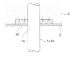
- FIG. 1 It is an exploded perspective view showing one embodiment of a headrest concerning the present invention. It is a sectional view of a headrest. It is a principal part enlarged sectional view of a headrest.
- the headrest HR as an integral foam is a bag-like trim cover 2 and a foam liquid (for example, foamable urethane) injected into the trim cover 2. It comprises a pad 3 as a foam which is cured and a stay 5 fixed in the pad 3.
- a foam liquid for example, foamable urethane
- the trim cover 2 which forms the skin is composed of a non-air-permeable synthetic skin and a wadding fixed to the back surface of the synthetic skin and made of a slab urethane foam material, and a two-layer type is used.
- the main body 10 of the headrest HR has a crown 12 coming in contact with the upper surface 11 of the seat back SB, and a front flap 13 hanging downward from the front end of the crown 12.
- the stay 5 is embedded in the pad 3 and extends in parallel with each other, the first and second L-shaped portions 5c and 5d, one end of the first L-shaped portion 5c and the second L-shaped portion 5d. Extending from the other end of the second L-shaped portion 5d and a first straight portion 5a extending from the other end of the first L-shaped portion 5c and a connecting portion 5e connecting horizontally with one end of the first L-shaped portion 5c And a second straight portion 5b parallel to the first straight portion 5a. Then, the front portions B of the first and second L-shaped portions 5c and 5d and the connecting portion 5e are in the front hanging portion 13.
- a seat back upper surface contact portion 12 a for contacting the upper surface 11 of the seat back SB is provided on the trim cover 2 covering the top of the head 12 of the main body portion 10 of the headrest HR.
- a stay through hole 14 into which the first and second straight portions 5a and 5b of the stay 5 are inserted is formed in 12a.
- the trim cover 2 and the urethane pad 3 are in close contact with each other and the headrest HR is adjusted to adjust the height of the headrest due to the special shape of the main body 10 and the stay 5. Is lifted, a load in the direction of the horizontal arrow A is applied to the main body 10. Therefore, stress is likely to be concentrated on the first and second straight portions 5a and 5b of the stay 5 in the vicinity of the stay through hole 14, whereby the pad 3 and the first and second straight portions 5a and 5b There was a problem that exfoliation was likely to occur between cities at the root.
- a doughnut disk shaped patch member 20 covering the periphery of the stay through hole 14 is fixed by sewing or bonding to the back surface of the seat back upper surface contact portion 12a, and the patch member 20 has an outer diameter of about 30 mm.
- the inner diameter is made of a material that is approximately the same as or slightly smaller than the diameter of the straight portions 5a and 5b, and has a thickness of about 3 to 5 mm. Since the patch member 20 has a donut disk shape, the straight portion of the stay can be easily penetrated. Further, since the patch member 20 is fixed inside the seat back upper surface contact portion 12a by sewing or bonding, the patch member 20 can be prevented from being displaced from the periphery of the stay through hole 14 and the stay through hole is reliably made.
- the peripheral edge of 14 can be covered. Since the patch member 20 has an inner diameter through which the stay 5 passes is substantially the same as or slightly smaller than the diameter of the straight portions 5a and 5b of the stay 5, the patch member 20 and the straight portions 5a and 5b of the stay 5 A sense of unity is good, and peeling between the patch member 20 and the straight portions 5 a and 5 b of the stay 5 can be prevented.
- the patch member 20 is formed of a material capable of being impregnated with a foaming liquid (for example, a foaming urethane) injected into the trim cover 2.
- a foaming liquid for example, a foaming urethane
- the patch member 20 there are wadding, non-woven fabric, felt and the like.
- such a patch member 20 is impregnated with a foaming solution S (for example, a foamable urethane) injected into the trim cover 2 when the headrest HR is formed.
- a foaming solution S for example, a foamable urethane
- the density of the material of the patch member 20 itself is increased, and the strength of the patch member 20 can be increased.
- the pad 3 formed of the foaming liquid S and the patch member 20 can be integrated, and the patch member 20 is not detached in the main body portion 10, and the pad 3 and the first and second straight portions 5a , 5b can prevent the occurrence of peeling between them.
- the patch member 20 may be formed of a metal which is not impregnated with the foaming liquid S in order to enhance the strength, the metal patch member has poor adhesion to the pad 3 and the patch member has been used for many years. There is a possibility that the trim cover 2 may be broken at the edge of the.
Landscapes
- Engineering & Computer Science (AREA)
- Aviation & Aerospace Engineering (AREA)
- Transportation (AREA)
- Mechanical Engineering (AREA)
- Manufacturing & Machinery (AREA)
- Seats For Vehicles (AREA)
- Chair Legs, Seat Parts, And Backrests (AREA)
Abstract
La présente invention vise à produire un appui-tête conçu de telle sorte qu'il ne se produit de séparation entre le rembourrage et le pied à proximité du trou traversant de pied. L'invention porte sur la surface arrière de la section en contact avec la surface supérieure de dossier de siège (12a) située au niveau de la partie supérieure (12) de l'appui-tête (HR), sur laquelle est fixée par couture ou collage une pièce de disque en forme de rondelle (20) destinée à recouvrir le bord du trou traversant de pied (14). En outre, la pièce (20) est formée d'un matériau dans lequel peut s'imprégner une solution moussante (par exemple, un uréthane moussant) qui est injectée à l'intérieur du revêtement de garniture (2). Pendant le moulage de l'appui-tête (HR), ladite pièce (20) s'imprègne de la solution moussante (S) (par exemple, un uréthane moussant) qui est injectée à l'intérieur du revêtement de garniture (2). Par conséquent, la densité du matériau de la pièce (20) est augmentée, en permettant d'augmenter la résistance de la pièce (20). En outre, l'intégration du rembourrage (3), qui est formé par la solution moussante (S), avec la pièce (20) est rendue possible et le déplacement de la pièce (20) à l'intérieur du corps (10) est supprimé.
Priority Applications (3)
| Application Number | Priority Date | Filing Date | Title |
|---|---|---|---|
| US14/888,842 US9616788B2 (en) | 2013-05-31 | 2014-05-13 | Headrest with headrest stay |
| CN201480028424.7A CN105407762A (zh) | 2013-05-31 | 2014-05-13 | 头枕 |
| EP14804777.2A EP3005906A4 (fr) | 2013-05-31 | 2014-05-13 | Appui-tête |
Applications Claiming Priority (2)
| Application Number | Priority Date | Filing Date | Title |
|---|---|---|---|
| JP2013-115297 | 2013-05-31 | ||
| JP2013115297A JP6059086B2 (ja) | 2013-05-31 | 2013-05-31 | ヘッドレスト |
Publications (1)
| Publication Number | Publication Date |
|---|---|
| WO2014192534A1 true WO2014192534A1 (fr) | 2014-12-04 |
Family
ID=51988571
Family Applications (1)
| Application Number | Title | Priority Date | Filing Date |
|---|---|---|---|
| PCT/JP2014/062688 Ceased WO2014192534A1 (fr) | 2013-05-31 | 2014-05-13 | Appui-tête |
Country Status (5)
| Country | Link |
|---|---|
| US (1) | US9616788B2 (fr) |
| EP (1) | EP3005906A4 (fr) |
| JP (1) | JP6059086B2 (fr) |
| CN (1) | CN105407762A (fr) |
| WO (1) | WO2014192534A1 (fr) |
Cited By (1)
| Publication number | Priority date | Publication date | Assignee | Title |
|---|---|---|---|---|
| CN105368437A (zh) * | 2015-11-26 | 2016-03-02 | 陕西延长石油(集团)有限责任公司研究院 | 一种含单过硫酸氢钾的羟丙基瓜胶压裂液及其制备方法 |
Families Citing this family (8)
| Publication number | Priority date | Publication date | Assignee | Title |
|---|---|---|---|---|
| WO2016049691A1 (fr) * | 2014-09-30 | 2016-04-07 | Cj Albert Builders Pty Ltd | Appui-tête et cou |
| EP3248832B1 (fr) | 2015-01-23 | 2021-06-30 | Delta Tooling Co., Ltd. | Procédé de fabrication d'appui-tête et appui-tête |
| US10676002B2 (en) * | 2017-12-19 | 2020-06-09 | Adient Engineering and IP GmbH | Vehicle seat with cantilevered headrest assembly and positioning system |
| WO2021054184A1 (fr) * | 2019-09-20 | 2021-03-25 | テイ・エス テック株式会社 | Appuie-tête |
| US11148570B2 (en) * | 2019-11-26 | 2021-10-19 | GM Global Technology Operations LLC | Actuating rear center head restraint |
| JP7764010B2 (ja) * | 2021-07-16 | 2025-11-05 | デルタ工業株式会社 | ヘッドレストの製造方法 |
| FR3127430B1 (fr) * | 2021-09-28 | 2024-06-14 | Tesca France | Procédé de réalisation d’un appui-tête de siège de véhicule automobile |
| FR3163618A1 (fr) * | 2024-06-20 | 2025-12-26 | Tesca France | Appui-tête de siège de véhicule automobile |
Citations (3)
| Publication number | Priority date | Publication date | Assignee | Title |
|---|---|---|---|---|
| JPH1118868A (ja) * | 1997-07-02 | 1999-01-26 | Takaya Kasei Kk | 表皮一体型ヘッドレスト及びその製造方法 |
| JP2006096125A (ja) | 2004-09-29 | 2006-04-13 | Tachi S Co Ltd | 一体発泡品 |
| JP2008206683A (ja) * | 2007-02-26 | 2008-09-11 | Tokai Chem Ind Ltd | 表皮一体ヘッドレストとその製造方法 |
Family Cites Families (6)
| Publication number | Priority date | Publication date | Assignee | Title |
|---|---|---|---|---|
| JPH04164404A (ja) * | 1990-10-29 | 1992-06-10 | Ikeda Bussan Co Ltd | 可動ヘッドレスト |
| JP4012028B2 (ja) * | 2002-09-27 | 2007-11-21 | ジョンソン コントロールズ オートモーティブ システムズ株式会社 | 自動車用シート |
| JP2007195768A (ja) * | 2006-01-27 | 2007-08-09 | Tachi S Co Ltd | フレーム付表皮一体発泡品 |
| JP2007330577A (ja) * | 2006-06-16 | 2007-12-27 | Takaya Kasei Kk | 表皮一体型ヘッドレストの表皮構造 |
| JP4955530B2 (ja) * | 2007-12-26 | 2012-06-20 | アキレス株式会社 | 表皮一体発泡成形用の表皮材 |
| CN102582485A (zh) * | 2011-01-14 | 2012-07-18 | 钱敏雅 | 汽车舒颈枕 |
-
2013
- 2013-05-31 JP JP2013115297A patent/JP6059086B2/ja not_active Expired - Fee Related
-
2014
- 2014-05-13 WO PCT/JP2014/062688 patent/WO2014192534A1/fr not_active Ceased
- 2014-05-13 EP EP14804777.2A patent/EP3005906A4/fr not_active Withdrawn
- 2014-05-13 US US14/888,842 patent/US9616788B2/en not_active Expired - Fee Related
- 2014-05-13 CN CN201480028424.7A patent/CN105407762A/zh active Pending
Patent Citations (3)
| Publication number | Priority date | Publication date | Assignee | Title |
|---|---|---|---|---|
| JPH1118868A (ja) * | 1997-07-02 | 1999-01-26 | Takaya Kasei Kk | 表皮一体型ヘッドレスト及びその製造方法 |
| JP2006096125A (ja) | 2004-09-29 | 2006-04-13 | Tachi S Co Ltd | 一体発泡品 |
| JP2008206683A (ja) * | 2007-02-26 | 2008-09-11 | Tokai Chem Ind Ltd | 表皮一体ヘッドレストとその製造方法 |
Non-Patent Citations (1)
| Title |
|---|
| See also references of EP3005906A4 * |
Cited By (2)
| Publication number | Priority date | Publication date | Assignee | Title |
|---|---|---|---|---|
| CN105368437A (zh) * | 2015-11-26 | 2016-03-02 | 陕西延长石油(集团)有限责任公司研究院 | 一种含单过硫酸氢钾的羟丙基瓜胶压裂液及其制备方法 |
| CN105368437B (zh) * | 2015-11-26 | 2018-02-06 | 陕西延长石油(集团)有限责任公司研究院 | 一种含单过硫酸氢钾的羟丙基瓜胶压裂液及其制备方法 |
Also Published As
| Publication number | Publication date |
|---|---|
| US9616788B2 (en) | 2017-04-11 |
| JP6059086B2 (ja) | 2017-01-11 |
| EP3005906A4 (fr) | 2017-01-18 |
| CN105407762A (zh) | 2016-03-16 |
| EP3005906A1 (fr) | 2016-04-13 |
| US20160059754A1 (en) | 2016-03-03 |
| JP2014233351A (ja) | 2014-12-15 |
Similar Documents
| Publication | Publication Date | Title |
|---|---|---|
| JP6059086B2 (ja) | ヘッドレスト | |
| US10112514B2 (en) | Piping for a motor vehicle cover | |
| US9707871B2 (en) | Headrest | |
| US8109576B2 (en) | Seat assembly | |
| US5630240A (en) | Cushion body structure comfortable to sit | |
| JP2010064636A (ja) | シートのアンカー部構造 | |
| JP5964198B2 (ja) | シートパッドの製造方法 | |
| JP6736212B2 (ja) | 車両用シートパッド及びその製造方法 | |
| JP2014069532A (ja) | シートパッド及びそのための発泡成形型 | |
| JP4247034B2 (ja) | 車両用シートクッション | |
| KR20170013721A (ko) | 차량용 시트커버의 구조 | |
| JP5848500B2 (ja) | シートパッド及びその製造方法 | |
| JP2009220359A (ja) | 発泡成形品 | |
| JP5985379B2 (ja) | シールテープ付きダクト入りシートパッド | |
| KR102167692B1 (ko) | 벨크로 결합을 이용한 차량용 탈착식 암레스트 | |
| JP6771818B2 (ja) | 車両用シートパッド及びその製造方法 | |
| KR102167691B1 (ko) | 밴드부를 구비한 차량용 탈착식 암레스트 | |
| JP2019025197A (ja) | 一体発泡パッド | |
| CN102555852B (zh) | 儿童汽车座 | |
| KR101104242B1 (ko) | 필로우탑 매트리스 및 이를 이용한 침대 매트리스 | |
| JP2010247822A (ja) | 車両用シート構造 | |
| JPS6026720Y2 (ja) | 車両用シ−ト | |
| JPH03159Y2 (fr) | ||
| KR101820368B1 (ko) | 메쉬의자용 좌판 | |
| JP6207689B2 (ja) | ダクト入りシートパッドの製造方法 |
Legal Events
| Date | Code | Title | Description |
|---|---|---|---|
| WWE | Wipo information: entry into national phase |
Ref document number: 201480028424.7 Country of ref document: CN |
|
| 121 | Ep: the epo has been informed by wipo that ep was designated in this application |
Ref document number: 14804777 Country of ref document: EP Kind code of ref document: A1 |
|
| WWE | Wipo information: entry into national phase |
Ref document number: 14888842 Country of ref document: US Ref document number: 2014804777 Country of ref document: EP |
|
| NENP | Non-entry into the national phase |
Ref country code: DE |