WO2014192577A1 - Dispositif de traitement d'image, procédé de traitement d'image et programme - Google Patents
Dispositif de traitement d'image, procédé de traitement d'image et programme Download PDFInfo
- Publication number
- WO2014192577A1 WO2014192577A1 PCT/JP2014/063210 JP2014063210W WO2014192577A1 WO 2014192577 A1 WO2014192577 A1 WO 2014192577A1 JP 2014063210 W JP2014063210 W JP 2014063210W WO 2014192577 A1 WO2014192577 A1 WO 2014192577A1
- Authority
- WO
- WIPO (PCT)
- Prior art keywords
- tone curve
- image processing
- image
- adjustment unit
- region
- Prior art date
- Legal status (The legal status is an assumption and is not a legal conclusion. Google has not performed a legal analysis and makes no representation as to the accuracy of the status listed.)
- Ceased
Links
Images


Classifications
-
- G—PHYSICS
- G06—COMPUTING OR CALCULATING; COUNTING
- G06T—IMAGE DATA PROCESSING OR GENERATION, IN GENERAL
- G06T5/00—Image enhancement or restoration
- G06T5/90—Dynamic range modification of images or parts thereof
- G06T5/94—Dynamic range modification of images or parts thereof based on local image properties, e.g. for local contrast enhancement
-
- H—ELECTRICITY
- H04—ELECTRIC COMMUNICATION TECHNIQUE
- H04N—PICTORIAL COMMUNICATION, e.g. TELEVISION
- H04N1/00—Scanning, transmission or reproduction of documents or the like, e.g. facsimile transmission; Details thereof
- H04N1/40—Picture signal circuits
- H04N1/407—Control or modification of tonal gradation or of extreme levels, e.g. background level
-
- G—PHYSICS
- G06—COMPUTING OR CALCULATING; COUNTING
- G06T—IMAGE DATA PROCESSING OR GENERATION, IN GENERAL
- G06T5/00—Image enhancement or restoration
- G06T5/90—Dynamic range modification of images or parts thereof
-
- G—PHYSICS
- G06—COMPUTING OR CALCULATING; COUNTING
- G06V—IMAGE OR VIDEO RECOGNITION OR UNDERSTANDING
- G06V40/00—Recognition of biometric, human-related or animal-related patterns in image or video data
- G06V40/10—Human or animal bodies, e.g. vehicle occupants or pedestrians; Body parts, e.g. hands
- G06V40/16—Human faces, e.g. facial parts, sketches or expressions
- G06V40/168—Feature extraction; Face representation
- G06V40/171—Local features and components; Facial parts ; Occluding parts, e.g. glasses; Geometrical relationships
-
- G—PHYSICS
- G06—COMPUTING OR CALCULATING; COUNTING
- G06T—IMAGE DATA PROCESSING OR GENERATION, IN GENERAL
- G06T2207/00—Indexing scheme for image analysis or image enhancement
- G06T2207/20—Special algorithmic details
- G06T2207/20004—Adaptive image processing
- G06T2207/20012—Locally adaptive
-
- G—PHYSICS
- G06—COMPUTING OR CALCULATING; COUNTING
- G06T—IMAGE DATA PROCESSING OR GENERATION, IN GENERAL
- G06T2207/00—Indexing scheme for image analysis or image enhancement
- G06T2207/20—Special algorithmic details
- G06T2207/20016—Hierarchical, coarse-to-fine, multiscale or multiresolution image processing; Pyramid transform
-
- G—PHYSICS
- G06—COMPUTING OR CALCULATING; COUNTING
- G06T—IMAGE DATA PROCESSING OR GENERATION, IN GENERAL
- G06T2207/00—Indexing scheme for image analysis or image enhancement
- G06T2207/20—Special algorithmic details
- G06T2207/20021—Dividing image into blocks, subimages or windows
-
- G—PHYSICS
- G06—COMPUTING OR CALCULATING; COUNTING
- G06T—IMAGE DATA PROCESSING OR GENERATION, IN GENERAL
- G06T2207/00—Indexing scheme for image analysis or image enhancement
- G06T2207/20—Special algorithmic details
- G06T2207/20172—Image enhancement details
- G06T2207/20208—High dynamic range [HDR] image processing
Definitions
- the present disclosure relates to an image processing device, an image processing method, and a program, and more particularly, to an image processing device, an image processing method, and a program that can make a main subject more prominent in an image.
- Patent Document 1 discloses a method of analyzing an image signal of a main subject area, setting an emphasis characteristic suitable for the entire image, and performing an emphasis process.
- enhancing the image may cause the image to fail. For example, when the brightness is increased with respect to the image, a portion that is white may occur. Conversely, the proposal described in Patent Document 1 may not provide a sufficient effect depending on the image.
- the present disclosure has been made in view of such a situation, and can make a main subject stand out more in an image.
- An image processing apparatus includes a tone curve adjustment unit that performs tone curve adjustment on at least one of a main subject region of an image and another region other than the main subject region, and the tone curve adjustment A contrast adjustment unit that performs contrast enhancement on the region where the tone curve adjustment is performed by the unit.
- the tone curve adjustment unit can perform tone curve adjustment to brighten the main subject area.
- the tone curve adjustment unit can perform tone curve adjustment to brighten the main subject area after adjusting the dynamic range.
- the tone curve adjustment unit can perform tone curve adjustment to brighten the main subject area according to the brightness of the other area.
- the tone curve adjustment unit can perform tone curve adjustment to brighten the main subject area in accordance with a user operation.
- the tone curve adjustment unit can perform tone curve adjustment to darken the other area.
- the tone curve adjustment unit can perform tone curve adjustment to darken the other area after adjusting the dynamic range.
- the tone curve adjustment unit can perform tone curve adjustment that darkens or brightens the other area according to the brightness of the other area.
- the tone curve adjustment unit can perform tone curve adjustment that darkens or brightens the other area in accordance with a user operation.
- the tone curve adjustment unit can perform tone curve adjustment that darkens a part other than the bright part of the other area.
- the contrast adjustment unit can inhibit contrast enhancement for the other region when the other region is included in the region where the tone curve adjustment is performed by the tone curve adjustment unit.
- the tone curve adjustment unit can perform tone curve adjustment that brightens the main subject area and darkens the other areas.
- the contrast adjustment unit can perform contrast enhancement in which the contrast enhancement characteristic is variable for each region according to the average value of the local regions of the image.
- the contrast adjustment unit includes a local level adjustment unit that adjusts an average value of the local region of the image, and the contrast enhancement characteristic is variable for each region according to the average value of the local region of the image adjusted by the local level adjustment unit. Contrast enhancement can be performed.
- the local level adjustment unit can adjust the average value of the local area of the image with a characteristic according to the bias of the luminance distribution.
- the local level adjustment unit can adjust the average value of the local region of the image in accordance with a user operation.
- the main subject area may include a face area and an area expanded from the face area toward the trunk.
- the amount of expansion decreases as the size of the face area increases.
- the image processing apparatus performs tone curve adjustment on at least one of a main subject region of an image and another region other than the main subject region, and the tone curve adjustment Contrast enhancement is performed on the area where the above has been performed.
- a program includes a tone curve adjustment unit that performs tone curve adjustment on at least one of a main subject region of an image and another region other than the main subject region, and the tone curve adjustment unit.
- the computer is caused to function as a contrast adjustment unit that performs contrast enhancement on the area on which the tone curve adjustment has been performed.
- tone curve adjustment is performed in at least one of the main subject region of the image and another region other than the main subject region. Then, contrast enhancement is performed on the area where the tone curve adjustment has been performed.
- the present disclosure it is possible to perform tone curve adjustment and contrast enhancement of an image.
- FIG. 26 is a block diagram illustrating another configuration example of an image processing apparatus to which the present technology is applied. It is a figure explaining the setting process of a main subject area. It is a figure explaining the setting process of a main subject area.
- FIG. 24 is a flowchart illustrating an example of image processing of the image processing apparatus in FIG. It is a figure which shows the pattern of a structure of the image process part for main parts. It is a figure which shows the pattern of a structure of the image process part for background parts. It is a figure which shows the example of the characteristic of the signal distribution adjustment process at the time of making area
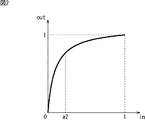
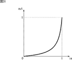
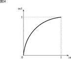
- FIG. 1 An example of a method for brightening an image to emphasize a main subject is to apply a gain to a signal.
- An example of characteristics when gain is applied is as shown in FIG.
- the horizontal axis represents the value (level) of the input signal
- the vertical axis represents the value (level) of the output signal.
- the signal is assumed to take a value of 0 to 1.
- whiteout occurs in a portion where the input signal is a1 (0 ⁇ a1 ⁇ 1) or more.
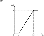
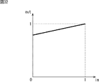
- a tone curve as shown in FIG. 2 is applied to a signal.
- overexposure as shown in FIG. 1 does not occur, but in the portion where the slope of the tone curve is smaller than 1, that is, the portion where the input signal is a2 (0 ⁇ a2 ⁇ 1) or more. Contrast is lowered.
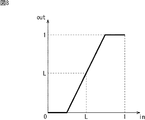
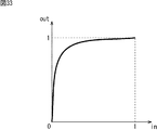
- the contrast can be increased as shown in FIG.
- blackout blocked up shadows
- whiteout occurs when the input signal is higher than b3. Will occur.
- the contrast enhancement is a normal contrast adjustment and enhances the output gain with respect to the input.
- adaptive contrast adjustment In order to reduce overexposure and underexposure due to normal contrast enhancement as described above, it is effective to optimize the contrast enhancement characteristics for each part of the image. Such processing is referred to as adaptive contrast adjustment in this specification.
- FIG. 4 is a block diagram illustrating an embodiment of an image processing apparatus to which the present technology is applied.
- an image processing apparatus 100 that enhances a predetermined portion of an image using tone curve adjustment and adaptive contrast adjustment is shown.
- the image processing apparatus 100 is configured to include a main part image processing unit 111-1, a background part image processing unit 111-2, and an image composition unit 112.
- the input image signal IN is supplied from the preceding stage (not shown) to the main image processing unit 111-1 and the background image processing unit 111-2.
- the main image processor 111-1 performs image processing using tone curve adjustment and adaptive contrast adjustment on the main subject region in the image of the input image signal IN.
- tone curve adjustment is performed to brighten the main part.
- the main image processing unit 111-1 supplies the image signal after the image processing to the image composition unit 112.
- the background image processing unit 111-2 performs image processing using tone curve adjustment and adaptive contrast adjustment on other regions other than the main subject in the image of the input image signal IN. In the background image processing unit 111-2, for example, tone curve adjustment for darkening the background portion is performed. The background image processing unit 111-2 supplies the image signal after the image processing to the image composition unit 112.
- the background image processing unit 111-2 may not perform image processing or may perform image processing. Conversely, when image processing is performed by the background image processing unit 111-2, the main image processing unit 111-1 may not perform image processing or may perform image processing. . That is, in the image processing apparatus 100, image processing is performed by at least one of them according to the degree of enhancement of the main subject.
- the main image processing unit 111-1 and the background image processing unit 111-2 are basically the same, although the processing target area, parameter values (characteristics), and effects required for the image are different. It is supposed to be configured. Therefore, hereinafter, the main part image processing unit 111-1 and the background part image processing unit 111-2 are collectively referred to as each part image processing unit 111 unless it is particularly necessary to distinguish between them.
- the image composition unit 112 uses an image (referred to as a main part image) from the main part image processing unit 111-1 for the main subject area, and the background part image processing unit 111-2 for the other areas. Is used to create a composite image. Note that the boundary portion between the main subject area and the other area may be combined so that the main image and the background image gradually change.
- the image composition unit 112 supplies the generated composite image signal as an output image signal OUT to a subsequent stage (not shown).
- the image composition unit 112 has been described as an example of composition for each picture. However, for example, it is also possible to configure the image composition unit 112 as a switch, and for each pixel, switch either the main part image or the background part image according to the region and output it to the subsequent stage. It is.
- FIG. 5 is a block diagram showing the configuration of the image processing unit for each unit.
- the common parts of the main image processing unit 111-1 and the background image processing unit 111-2 will be described together.
- a configuration example of each of the main image processing unit 111-1 and the background image processing unit 111-2 will be described later with reference to FIGS.
- the image processing unit 111 for each unit is configured to include a tone curve adjusting unit 121 and an adaptive contrast adjusting unit 122.
- the tone curve adjustment unit 121 adjusts the tone curve for the region to be the target of the input image signal IN, and supplies the image signal on which the tone curve has been adjusted to the adaptive contrast adjustment unit 122.
- the adaptive contrast adjustment unit 122 performs adaptive contrast adjustment on the region that is the target of the image whose tone curve has been adjusted by the tone curve adjustment unit 121.
- the adaptive contrast adjustment unit 122 supplies the output image signal OUT after the adaptive contrast processing to the subsequent stage.
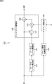
- the adaptive contrast adjustment unit 122 is configured to include a local level detection unit 131 and a contrast adjustment unit 132 in the example of FIG.
- the local level detection unit 131 obtains the level of the peripheral region of the target pixel (hereinafter referred to as a local level), and is configured by, for example, a low-pass filter.
- the local level detection unit 131 may not be a low-pass filter as long as the local level can be extracted.
- the lower the cutoff frequency of the low-pass filter the lower the contrast of the low band.
- a filter that averages a region larger than about 1/100 (area ratio) of the image size is suitable.
- a filter size of about 1/10 to 1/2 of the short side size of the image is preferable. If it is smaller than that, it becomes close to detail emphasis and the contrast emphasis effect is weak. On the other hand, if it is larger than that, it becomes close to uniform contrast enhancement in the screen, and does not become adaptive contrast enhancement.
- the above sizes specifically, for example, about 1/5 of the short side size of the image is more preferable.
- the local level detection unit 131 outputs the obtained local level signal (for example, the average value of the local levels) to the subtracter 141 of the contrast adjustment unit 132.
- the contrast adjustment unit 132 subtracts the local level signal from the image signal on which the tone curve has been adjusted, and adds the result to the image signal on which the tone curve has been adjusted to obtain an output image signal OUT. Is.
- the contrast adjustment unit 132 includes a subtracter 141 and an adder 142. That is, the subtractor 141 subtracts the local level signal from the image signal on which the tone curve has been adjusted, and outputs the result to the adder 142.
- the adder 142 adds the subtraction result of the subtracter 141 to the image signal whose tone curve has been adjusted, and outputs the output image signal OUT as a result thereof to the subsequent stage.
- the processing characteristics of the contrast adjustment unit 132 will be described with reference to FIGS.
- the local level L is small.
- the characteristics shown in FIG. 7 are obtained, and the contrast adjustment unit 132 performs contrast enhancement with a small blackout range and a large overexposure range. Done.
- contrast adjustment can be performed in which blackout and overexposure hardly occur.
- the local level L is medium. Therefore, for example, the characteristics shown in FIG. 8 are obtained.
- the blackout range and the whiteout range are the same. Some degree of contrast enhancement is performed. However, in this case, since the image signal is an intermediate region, the blackout range and overexposure range are small, and as a result, contrast enhancement in which blackout and overexposure hardly occur can be performed.
- the contrast adjustment unit 132 performs contrast enhancement with a large blackout range and a small overexposure range. Done.
- the image signal is large, there are few signals in the blackout range, and as a result, it is possible to perform contrast adjustment in which blackout and whiteout hardly occur.
- the contrast adjustment unit 132 performs adaptive contrast enhancement according to the local level from the local level detection unit 131. As a result, it is possible to perform contrast adjustment that is less likely to cause overexposure and underexposure.
- FIG. 10 is a block diagram illustrating a configuration example of the tone curve adjusting unit in FIG.
- the tone curve adjustment unit 121 is configured to include a D (Dynamic) range adjustment unit 151 and a signal distribution adjustment unit 152.
- the D range adjustment unit 151 adjusts the dynamic range of the image of the input image signal IN.
- the D range adjustment unit 151 supplies the image signal with the adjusted dynamic range of the image to the signal distribution adjustment unit 152.
- the D range adjustment unit 151 detects the distribution of the image signal and adjusts the signal level so that the dynamic range can be utilized effectively. Note that the detection of the distribution of the image signal may be performed on the entire screen or limited to a specific area.
- the signal distribution adjustment unit 152 adjusts the signal distribution of the image signal and enhances the image.
- the enhanced image is supplied to the adaptive contrast adjustment unit 122.
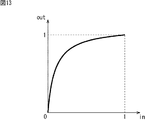
- the signal distribution adjustment unit 152 raises the average value of the signal level to make it brighter.
- An example highlighting (region) is shown.
- the image signal emphasized by the signal distribution adjustment unit 152 as described above is supplied to the adaptive contrast adjustment unit 122.
- the input image signal IN is supplied from the preceding stage (not shown) to the main image processing unit 111-1 and the background image processing unit 111-2.
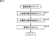
- step S111 the main image processing unit 111-1 performs main image processing.
- step S112 the background image processing unit 111-2 performs background image processing.
- the image processing for main part and the image processing for background part will be described in detail later with reference to FIG. 15 as the image processing for each part.
- step S111 image processing using tone curve adjustment and adaptive contrast adjustment is performed on the region of the main subject, and the image signal after the image processing is supplied to the image composition unit 112.
- step S112 image processing using tone curve adjustment and adaptive contrast adjustment is performed on the region other than the main subject, and the image signal after the image processing is supplied to the image composition unit 112. Is done.
- steps S111 and S112 may be performed in parallel. Alternatively, either one may be performed by external control or the like, and the input image signal IN may be supplied to the image composition unit 112 as it is on the other.
- step S113 the image composition unit 112 synthesizes images. That is, the image composition unit 112 creates a composite image using the main part image from the main part image processing unit 111-1 and the background image from the background part image processing unit 111-2. The generated composite image signal is supplied as an output image signal OUT to a subsequent stage (not shown).
- step S131 the D range adjustment unit 151 adjusts the dynamic range of the image of the input image signal IN.
- the D range adjustment unit 151 supplies the image signal whose dynamic range has been adjusted to the signal distribution adjustment unit 152.
- step S132 the signal distribution adjustment unit 152 adjusts the signal distribution of the image signal to enhance the image. For example, the adjustment of emphasizing the main subject region is performed by raising the average value of the signal level to make it brighter.
- the enhanced image is supplied to the adaptive contrast adjustment unit 122.
- step S133 the local level detection unit 131 detects a local level that is the level of the peripheral region of the target pixel.
- the local level detection unit 131 outputs the detected local level signal (for example, an average value of local levels) to the contrast adjustment unit 132.
- step S134 the contrast adjustment unit 132 subtracts the local level signal from the image signal on which the tone curve has been adjusted, and adds the result to the image signal on which the tone curve has been adjusted, thereby outputting an output image.
- the contrast is adjusted by obtaining the signal OUT.
- the subtracter 141 subtracts the local level signal from the image signal on which the tone curve has been adjusted, and outputs the result to the adder 142.
- the adder 142 adds the subtraction result of the subtracter 141 to the image signal whose tone curve has been adjusted, and outputs the output image signal OUT as a result thereof to the subsequent stage.
- adaptive contrast adjustment is performed according to the detected local level, so that contrast enhancement that hardly causes blackout and overexposure is performed. be able to. Furthermore, since the enhancement is performed after the main subject region is emphasized, the main subject can be made more prominent in the image.
- FIG. 16 is a block diagram illustrating another configuration example of the adaptive contrast adjustment unit in FIG.
- the adaptive contrast adjustment unit 122 is configured to include a local level detection unit 131, a local level adjustment unit 161, a contrast adjustment unit 162, a gain adjustment coefficient setting unit 163, and a gain adjustment unit 164. Yes.
- 16 is similar to the adaptive contrast adjustment unit 122 in FIG. 5 in that the adaptive contrast adjustment unit 122 in FIG.
- the adaptive contrast adjusting unit 122 in FIG. 16 is different from the adaptive contrast adjusting unit 122 in FIG. 5 in that the contrast adjusting unit 132 is replaced with a contrast adjusting unit 162.
- the adaptive contrast adjusting unit 122 in FIG. 16 is different from the adaptive contrast adjustment unit 122 in FIG. 5 in that it includes a local level adjustment unit 161, a gain adjustment coefficient setting unit 163, and a gain adjustment unit 164.
- the local level signal from the local level detection unit 131 is supplied to the local level adjustment unit 161.
- the local level adjustment unit 161 adjusts the local level obtained by the local level detection unit 131.
- the local level adjustment unit 161 supplies the adjusted local level signal to the contrast adjustment unit 162.
- the contrast adjustment unit 162 subtracts the local level signal from the image signal on which the tone curve has been adjusted, adds the gain to the result, and adds the result to the image signal on which the tone curve has been adjusted. An output image signal OUT is obtained.
- the contrast adjustment unit 162 includes the subtracter 141 and the adder 142, and is the same as the contrast adjustment unit 132 in FIG.
- the contrast adjustment unit 162 is different from the contrast adjustment unit 132 of FIG. 5 in that a multiplier 171 for multiplying the gain from the gain adjustment unit 164 is added.
- the subtracter 141 subtracts the local level signal from the image signal on which the tone curve has been adjusted, and outputs the result to the multiplier 171.
- the multiplier 171 multiplies the result subtracted by the subtracter 141 by the gain from the gain adjustment unit 164.
- the multiplier 171 outputs the result multiplied by the gain to the adder 142.
- the adder 142 adds the gain multiplication result by the multiplier 171 to the image signal whose tone curve has been adjusted, and outputs the resultant output image signal OUT to the subsequent stage.
- the input image signal IN from the previous stage is supplied to the local level detection unit 131 and the gain adjustment coefficient setting unit 163.
- the gain adjustment coefficient setting unit 163 obtains and sets a coefficient for adjusting the gain according to the input image signal IN, and supplies the set coefficient to the gain adjustment unit 164.
- the gain adjustment unit 164 adjusts the gain by multiplying the preset gain G by the coefficient obtained by the gain adjustment coefficient setting unit 163.
- the gain adjusted by the gain adjusting unit 164 is supplied to the multiplier 171 of the contrast adjusting unit 162.
- the local level adjustment unit 161 will be described.
- the solid line represents an example of the characteristics of the local level adjustment unit 161.
- the local level adjustment unit 161 makes the level of the output signal (hereinafter referred to as the output level) smaller than the input level. Further, the local level adjustment unit 161 makes the output level larger than the input level when the input level is larger than b.
- the local level L shown in FIG. 7 is shifted to a smaller direction, and blackout is further reduced. become.
- the local level becomes larger, so that the local level L shown in FIG. 9 is shifted in the larger direction, and the overexposure is further reduced.
- the characteristics of the local level adjustment unit 161 are expressed as a solid line in the example of FIG. 18, for example.
- b is set smaller than in the example of FIG.
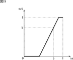
- the characteristic of the local level adjustment unit 161 is represented as a solid line in FIG. 19, for example.
- b is set larger than in the example of FIG.
- the local level of the image (for example, the average value of the local region) is adjusted with time according to the bias of the luminance distribution.
- the gain adjustment coefficient setting unit 163 Next, the gain adjustment coefficient setting unit 163 will be described.
- the solid line represents an example of the characteristics of the gain adjustment coefficient setting unit.
- the characteristics of the gain adjustment coefficient setting unit 163 are determined in consideration of the characteristics of the signal distribution adjustment unit 152. As described above, as a result of the signal distribution adjustment, the contrast decreases as the slope of FIG. 13 is smaller (that is, the signal level is higher). Therefore, by providing the gain adjustment coefficient setting unit 163 with a characteristic proportional to the inverse of the derivative of the characteristic in FIG. 13, the total contrast enhancement characteristic becomes constant. As a result, it is possible to reduce blackout when the gain is increased.
- step S161 the D range adjustment unit 151 adjusts the dynamic range of the image of the input image signal IN.
- the D range adjustment unit 151 supplies the image signal with the adjusted dynamic range of the image to the signal distribution adjustment unit 152.
- step S162 the signal distribution adjustment unit 152 adjusts the signal distribution of the image signal to enhance the image. For example, the adjustment of emphasizing the main subject region is performed by raising the average value of the signal level to make it brighter.
- the enhanced image is supplied to the adaptive contrast adjustment unit 122.
- step S163 the local level detection unit 131 detects a local level that is the level of the peripheral region of the target pixel.
- the local level detection unit 131 outputs the detected local level signal to the local level adjustment unit 161.
- step S164 the local level adjustment unit 161 adjusts the local level obtained by the local level detection unit 131.
- the local level adjustment unit 161 supplies the adjusted local level signal to the contrast adjustment unit 162.
- step S165 the gain adjustment coefficient setting unit 163 obtains and sets a coefficient for adjusting the gain according to the input image signal IN from the signal distribution adjustment unit 152, and supplies the set coefficient to the gain adjustment unit 164. .
- step S166 the gain adjustment unit 164 adjusts the gain by multiplying the preset gain G by the coefficient obtained by the gain adjustment coefficient setting unit 163.
- the gain adjusted by the gain adjusting unit 164 is supplied to the multiplier 171 of the contrast adjusting unit 162.
- step S167 the contrast adjustment unit 162 subtracts the local level signal from the image signal on which the tone curve has been adjusted. Then, the contrast adjusting unit 162 adds the gain obtained by multiplying the result to the image signal on which the tone curve has been adjusted to obtain the output image signal OUT, thereby adjusting (emphasizing) the contrast.
- the subtracter 141 subtracts the local level signal from the image signal on which the tone curve has been adjusted, and outputs the result to the multiplier 171.
- the multiplier 171 multiplies the result subtracted by the subtracter 141 by the gain from the gain adjustment unit 164.
- the multiplier 171 outputs the result multiplied by the gain to the adder 142.
- the adder 142 adds the gain multiplication result by the multiplier 171 to the image signal whose tone curve has been adjusted, and outputs the resultant output image signal OUT to the subsequent stage.
- FIG. 23 is a block diagram illustrating another embodiment of an image processing apparatus to which the present technology is applied.
- the image processing apparatus 200 of FIG. 23 is common to the image processing apparatus 100 of FIG. 4 in that it includes a main part image processing unit 111-1, a background part image processing unit 111-2, and an image composition unit 112. Yes.
- the image processing apparatus 200 of FIG. 23 is different from the image processing apparatus 100 of FIG. 4 in that a main subject region setting unit 211 is added.
- the main subject area setting unit 211 detects a main subject in the image and sets a main subject area assumed from the detected main subject information.
- the main subject area setting unit 211 detects the main subject in the image.
- face detection is used assuming that the main subject is a person is taken as an example.
- face area information is obtained by face detection and used as main subject information. It is also possible for the user to set the main subject area.
- the main subject area setting unit 211 sets a main subject area assumed from the main subject information.
- main subject detection is face detection
- a human region assumed from the face region is set as the main subject region.
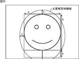
- an ellipse (major axis a + b + 2c, minor axis a + 2c) whose diameter is a size obtained by adding an additional value c to the size of the area obtained by adding the extended area b to the face area a is the main subject area.
- An example is shown. This is a case where the subject appears relatively small, and the extended region b is set to include the vicinity of the trunk.
- an ellipse (major axis a + b + 2c, minor axis a + 2c) having a diameter obtained by adding an additional value c to the size of the area obtained by adding the extended area b to the face area a is mainly used.
- An example of a subject area is shown. This is a case where the subject is relatively large, and the extended region b is set so as to include the vicinity of the neck.
- the extended region b is included up to the vicinity of the chest.
- the expansion amount from the face area to the trunk direction is set to be larger as the face size is smaller.
- such a characteristic is indicated by a solid line.
- the additional value c is substantially constant regardless of the face size.
- the main subject region When there are a plurality of main subjects, a combination of these regions may be used as the main subject region, or any one of them may be selected as the main subject region.
- the main subject region When the main subject is not detected, the main subject region may be set near the center of the screen. Furthermore, even when the main subject is detected, the area may be expanded toward the center of the screen when it is biased toward the edge of the screen. Further, the detected main subject may be used as the main subject region without expanding the main subject (that is, the detected region may be used as the main subject region).
- boundary blurring may be performed on this main subject area by a low-pass filter or the like.
- the input image signal IN is supplied to the main subject region setting unit 211, the main image processing unit 111-1, and the background image processing unit 111-2 from the preceding stage (not shown).
- step S211 the main subject area setting unit 211 detects the main subject of the image of the input image signal IN.
- face area information is obtained by face detection and used as main subject information.
- step S212 the main subject region setting unit 211 sets a main subject region assumed from the main subject information. For example, when the main subject detection is face detection, a person region assumed from the face region is set as the main subject region.
- step S213 the main part image processing unit 111-1 performs main part image processing.
- step S214 the background image processing unit 111-2 performs background image processing.
- the image processing for main part and the image processing for background part are basically the same as the image processing for each part described above with reference to FIG. Is done.
- step S213 image processing using tone curve adjustment and adaptive contrast adjustment is performed on the region of the main subject, and the image signal after the image processing is supplied to the image composition unit 112.
- step S214 image processing using tone curve adjustment and adaptive contrast adjustment is performed on regions other than the main subject, and the image signal after image processing is supplied to the image composition unit 112. Is done.
- steps S213 and S214 may be performed in parallel, or one of them is performed by external control or the like.
- IN may be supplied to the image composition unit 112 as it is.
- step S215 the image composition unit 112 composes an image.
- the image composition unit 112 creates a composite image using the main part image from the main part image processing unit 111-1 and the background part image from the background part image processing unit 111-2.
- the generated composite image signal is supplied as an output image signal OUT to a subsequent stage (not shown).
- FIG. 28 is a diagram showing a configuration pattern of the main image processing unit 111-1.
- the main image processing unit 111-1 creates an image that gives a distinctive impression by brightening the image and enhancing the contrast.
- Main part image processing section 111-1 includes, as configuration 1, D range adjustment section 151, signal distribution adjustment section 152, and adaptive contrast adjustment section 122 as described above with reference to FIGS. Configured as follows.
- the D range adjustment unit 151 detects the image signal distribution for the main subject region of the image and adjusts the dynamic range as described above with reference to FIGS.
- the signal distribution adjustment unit 152 enhances the image (its main subject area) by, for example, raising the average value of the signal level using the characteristic shown in FIG.
- the adaptive contrast adjustment unit 122 performs contrast enhancement with less overexposure by performing adaptive contrast enhancement, for example, as described above with reference to FIGS.
- the D range adjustment unit 151 is not an essential configuration requirement.
- the main image processing unit 111-1 is configured to include a signal distribution adjustment unit 152 and an adaptive contrast adjustment unit 122 as configuration 2.
- the D range adjustment is effective when the luminance distribution of the original image is narrow.
- adjusting the D range will make the image look hazy. That is, if the image having a narrower luminance distribution range is configured as 1, the image becomes clearer.
- the configuration of the main image processing unit 111-1 is normally configuration 2, and is automatically switched to configuration 1 when the luminance distribution range of the image is narrow.
- the characteristics shown in FIGS. 7 to 9 are automatically switched according to the output level L of the low-pass filter serving as the local level detection unit 131.
- the characteristics shown in FIGS. 17 to 19 are usually the characteristics shown in FIG. Further, when the luminance distribution is biased toward high luminance, the characteristic of FIG. 18 is switched with emphasis on over-exposure reduction, and when the luminance distribution is biased toward low luminance, emphasis is placed on black solid reduction. Switch to characteristics.
- FIG. 29 is a diagram showing a configuration pattern of the background image processing unit 111-2.
- the background image processing unit 111-2 creates an image in which the main part gives a more distinctive impression by enhancing contrast while darkening the image. Note that just darkening the background has the effect of making the main parts stand out, but further emphasizing the contrast makes it possible to create brighter parts in the dark, resulting in an effect resembling painting expression by the light and dark method.
- background image processing unit 111-2 includes D range adjustment unit 151, signal distribution adjustment unit 152, and adaptive contrast adjustment unit 122 as described above with reference to FIGS. Configured as follows.
- the configuration is the same as that of the main image processing unit 111-1 described above with reference to FIG. 28, but their characteristics (parameter characteristics) are different.
- the D range adjustment unit 151 detects the image signal distribution for the main subject region of the image or the entire image, and adjusts the dynamic range as described above with reference to FIGS.
- the signal distribution adjustment unit 152 darkens the signal level by reducing the signal level using, for example, characteristics as shown in FIG.
- the adaptive contrast adjustment unit 122 performs contrast enhancement with less overexposure by performing adaptive contrast enhancement as described above, for example.
- the D range adjustment unit 151 is not an essential configuration requirement. That is, in the case of the configuration 2-1, the D range adjustment unit 151 does not normally operate and allows the signal to pass through.
- the adaptive contrast adjustment unit 122 other than the D range adjustment unit 151 does not work. Also good. In other words, contrast enhancement for areas other than the main subject may be prohibited. That is, in this case, for example, the signal distribution adjustment unit 152 enhances the contrast by reducing the signal level by using the characteristics as shown in FIG. 31 and making the originally bright part not so dark. Because you can.
- the characteristic of the signal distribution adjusting unit 152 is set to be very bright by changing the intercept of the linear function in the plus direction as shown in FIG. 32, for example, the background is darkened.
- the main subject emphasis effect can be obtained by brightening the background.
- the configuration of the background image processing unit 111-2 is usually the configuration 2-1 (or configuration 2-2), and the luminance distribution range of the image. Automatically switches to configuration 1 when the
- FIG. 30 or 31 and FIG. 32 are switched to FIG. 30 or FIG. 31 when the background is darker than a certain level, and when the background is brighter than a certain level, It switches to FIG.
- the characteristics shown in FIGS. 20 and 21 are switched to FIG. 20 when the low luminance component is large, and when the low luminance component is small, the characteristics shown in FIG. Can be switched.
- image processing for enhancing an image is applied to a luminance signal.
- a gain corresponding to the resulting luminance change to the color signal. That is, if the luminance signal changes from Yin to Yout, a color signal suitable for the luminance signal can be obtained by applying a gain of Yout / Yin to the color signal.
- a process of erasing only the background portion of the color difference signal may be performed.
- the main subject stand out by making contrast enhancement while making the main subject region brighter. Further, the main subject can be made more conspicuous by performing contrast enhancement while darkening the background region other than the main subject region.
- the present technology is applied not only to the image processing device but also to an imaging device, a server, and the like.
- the imaging apparatus, or the server for example, the following processing modes are provided, and each processing unit constituting the main part or background part image processing unit described above according to the shooting mode. It is possible to set the characteristics.
- the low contrast mode is a mode used in the case of an image with overcast or haze. When this mode is selected, the processing of the D range adjustment unit 151 is performed.
- the subject exposure under mode is a mode selected when the subject (main part) is darker than usual because the background is bright.
- this mode is selected, the effect of brightening in the signal distribution adjusting unit 152 of the main image processing unit 111-1 is strengthened as shown in the characteristics shown in FIG.
- blackout reduction is emphasized.
- the subject part overexposure mode is selected when the background is dark and the subject part is brighter than usual.
- this mode is selected, the effect of brightening in the signal distribution adjusting unit 152 of the main image processing unit 111-1 is weakened as shown in the characteristics shown in FIG.
- the setting of emphasis on overexposure is made.
- the normal mode darkens the background, while the background skipping (background white skipping) mode is selected when the image wants to whiten the background.
- the signal distribution adjusting unit 152 of the background image processing unit 111-2 has a very bright characteristic. At this time, the gain applied to the color signal of the background portion is reduced to perform achromatic processing.
- the above four shooting modes can be selected by the user, and automatic mode setting can also be performed by image processing or the like.
- the difference between the characteristics shown in FIG. 30 or 31 and the characteristics shown in FIG. 32 is whether the background is dark or bright. Therefore, when the background is darker than a certain level, the characteristics shown in FIG. 30 or FIG. 31 can be used. When the background is brighter than a certain level, the characteristics shown in FIG. 32 can be used.
- the main image processing unit 111-1, the background image processing unit 111-2, and the image processing unit are divided into two.
- the configuration is not limited thereto.
- the processing may be switched in one image processing unit without dividing the image processing unit, and the main image and the background image may be processed.
- the series of processes described above can be executed by hardware or software.
- a program constituting the software is installed in the computer.
- the computer includes, for example, a general-purpose personal computer capable of executing various functions by installing various programs by installing a computer incorporated in dedicated hardware.
- FIG. 35 shows an example of the hardware configuration of a computer that executes the above-described series of processing by a program.
- a CPU Central Processing Unit
- ROM Read Only Memory
- RAM Random Access Memory
- an input / output interface 805 is connected to the bus 804.
- An input unit 806, an output unit 807, a storage unit 808, a communication unit 809, and a drive 810 are connected to the input / output interface 805.
- the input unit 806 includes a keyboard, a mouse, a microphone, and the like.
- the output unit 807 includes a display, a speaker, and the like.
- the storage unit 808 includes a hard disk, a nonvolatile memory, and the like.
- the communication unit 809 includes a network interface or the like.
- the drive 810 drives a removable recording medium 811 such as a magnetic disk, an optical disk, a magneto-optical disk, or a semiconductor memory.
- the CPU 801 loads the program stored in the storage unit 808 to the RAM 803 via the input / output interface 805 and the bus 804 and executes the program, for example. Is performed.
- the program executed by the computer (CPU 801) can be provided by being recorded in a removable recording medium 811 as a package medium, for example.
- the program can be provided via a wired or wireless transmission medium such as a local area network, the Internet, or digital satellite broadcasting.
- the program can be installed in the storage unit 808 via the input / output interface 805 by attaching the removable recording medium 811 to the drive 810.
- the program can be received by the communication unit 809 via a wired or wireless transmission medium and installed in the storage unit 808.
- the program can be installed in the ROM 802 or the storage unit 808 in advance.
- the program executed by the computer may be a program that is processed in time series in the order described in this specification, or in parallel or at a necessary timing such as when a call is made. It may be a program for processing.
- steps describing the series of processes described above are not limited to the processes performed in time series according to the described order, but are not necessarily performed in time series, either in parallel or individually.
- the process to be executed is also included.
- the present technology can take a configuration of cloud computing in which one function is shared by a plurality of devices via a network and is jointly processed.
- each step described in the above flowchart can be executed by one device or can be shared by a plurality of devices.
- the plurality of processes included in the one step can be executed by being shared by a plurality of apparatuses in addition to being executed by one apparatus.
- the configuration described as one device (or processing unit) may be divided and configured as a plurality of devices (or processing units).
- the configurations described above as a plurality of devices (or processing units) may be combined into a single device (or processing unit).
- a configuration other than that described above may be added to the configuration of each device (or each processing unit).
- a part of the configuration of a certain device (or processing unit) may be included in the configuration of another device (or other processing unit). . That is, the present technology is not limited to the above-described embodiment, and various modifications can be made without departing from the gist of the present technology.
- this technique can also take the following structures.
- a tone curve adjusting unit that performs tone curve adjustment on at least one of the main subject region of the image and another region other than the main subject region;
- An image processing apparatus comprising: a contrast adjustment unit that performs contrast enhancement on a region in which tone curve adjustment has been performed by the tone curve adjustment unit.
- the image processing apparatus according to (1) wherein the tone curve adjustment unit performs tone curve adjustment that brightens the main subject region.
- the tone curve adjustment unit performs tone curve adjustment to brighten the main subject region after adjusting the dynamic range.
- the tone curve adjustment unit performs tone curve adjustment that brightens the main subject area according to the brightness of the other area.
- the image processing device (9) The image processing device according to (6), wherein the tone curve adjustment unit performs tone curve adjustment that darkens or brightens the other region in accordance with a user operation. (10) The image processing device according to (6), wherein the tone curve adjustment unit performs tone curve adjustment that darkens a portion other than the bright portion of the other region. (11) The contrast adjustment unit prohibits contrast enhancement for the other region when the other region is included in the region on which the tone curve adjustment is performed by the tone curve adjustment unit. An image processing apparatus according to 1. (12) The image processing device according to any one of (1) to (11), wherein the tone curve adjustment unit performs tone curve adjustment that brightens the main subject region and darkens the other region.
- the image processing device performs contrast enhancement in which a contrast enhancement characteristic is variable for each region according to an average value of local regions of the image.
- the contrast adjustment unit includes: A local level adjustment unit for adjusting an average value of a local region of the image; The image processing apparatus according to (13), wherein contrast enhancement is performed by changing a contrast enhancement characteristic for each region based on an average value of local regions of the image adjusted by the local level adjustment unit.
- the local level adjustment unit adjusts an average value of a local region of the image with a characteristic according to a bias of a luminance distribution.
- the image processing device (16) The image processing device according to (14), wherein the local level adjustment unit adjusts an average value of a local region of the image according to a user operation.
- the main subject region includes a face region and a region expanded from the face region toward the trunk.
- the amount of expansion decreases as the size of the face area increases.
- the image processing apparatus Perform tone curve adjustment on at least one of the main subject region of the image and the other region other than the main subject region, An image processing method in which contrast enhancement is performed on an area on which the tone curve adjustment has been performed.
- tone curve adjustment unit that performs tone curve adjustment on at least one of the main subject region of the image and another region other than the main subject region;
- a program that causes a computer to function as a contrast adjustment unit that performs contrast enhancement on an area in which tone curve adjustment has been performed by the tone curve adjustment unit.
- 100 image processing device 111 image processing unit for each part, 111-1 main image processing unit, 111-2 background image processing unit, 112 image composition unit, 121 tone curve adjustment unit, 122 adaptive contrast adjustment unit, 131 local level detection unit, 132 contrast adjustment unit, 141 subtractor, 142 adder, 151 D range adjustment unit, 152 signal distribution unit, 161 local level adjustment unit, 162 contrast adjustment unit, 163 gain adjustment coefficient setting unit, 164 gain Adjustment section, 200 main subject area setting section
Landscapes
- Engineering & Computer Science (AREA)
- Physics & Mathematics (AREA)
- General Physics & Mathematics (AREA)
- Theoretical Computer Science (AREA)
- Multimedia (AREA)
- Health & Medical Sciences (AREA)
- Oral & Maxillofacial Surgery (AREA)
- Signal Processing (AREA)
- General Health & Medical Sciences (AREA)
- Computer Vision & Pattern Recognition (AREA)
- Human Computer Interaction (AREA)
- Image Processing (AREA)
Abstract
La présente invention concerne un dispositif de traitement d'image, un procédé de traitement d'image et un programme qui sont capables de rendre plus proéminent un sujet principal de réalisation d'image présent dans une image. Une unité d'ajustement de courbe de tonalité ajuste la courbe de tonalité d'une région pour laquelle des signaux d'image d'entrée vont être introduits, et envoie les signaux d'image dont la courbe de tonalité a été ajustée à une unité de détection de niveau local. L'unité de détection de niveau local trouve le niveau local. Une unité d'ajustement de contraste exécute une amélioration de contraste adaptative en fonction du niveau local déterminé par l'unité de détection de niveau local. La présente invention peut s'appliquer, par exemple, à un dispositif de traitement d'image qui renforce une partie prescrite d'une image en utilisant un ajustement de courbe de tonalité et une amélioration de contraste adaptative.
Priority Applications (1)
| Application Number | Priority Date | Filing Date | Title |
|---|---|---|---|
| US14/893,917 US9754362B2 (en) | 2013-05-31 | 2014-05-19 | Image processing apparatus, image processing method, and program |
Applications Claiming Priority (2)
| Application Number | Priority Date | Filing Date | Title |
|---|---|---|---|
| JP2013115723 | 2013-05-31 | ||
| JP2013-115723 | 2013-05-31 |
Publications (1)
| Publication Number | Publication Date |
|---|---|
| WO2014192577A1 true WO2014192577A1 (fr) | 2014-12-04 |
Family
ID=51988612
Family Applications (1)
| Application Number | Title | Priority Date | Filing Date |
|---|---|---|---|
| PCT/JP2014/063210 Ceased WO2014192577A1 (fr) | 2013-05-31 | 2014-05-19 | Dispositif de traitement d'image, procédé de traitement d'image et programme |
Country Status (2)
| Country | Link |
|---|---|
| US (1) | US9754362B2 (fr) |
| WO (1) | WO2014192577A1 (fr) |
Cited By (1)
| Publication number | Priority date | Publication date | Assignee | Title |
|---|---|---|---|---|
| WO2018047557A1 (fr) * | 2016-09-06 | 2018-03-15 | ソニー株式会社 | Appareil et procédé de traitement d'image, et programme |
Families Citing this family (4)
| Publication number | Priority date | Publication date | Assignee | Title |
|---|---|---|---|---|
| US12327341B2 (en) * | 2019-06-20 | 2025-06-10 | Lg Electronics Inc. | Display device |
| US11430093B2 (en) | 2019-10-01 | 2022-08-30 | Microsoft Technology Licensing, Llc | Face-based tone curve adjustment |
| EP4047926A4 (fr) * | 2019-10-16 | 2022-11-23 | Panasonic Intellectual Property Management Co., Ltd. | Procédé de traitement d'image, système de traitement d'image et dispositif de traitement d'image |
| EP4400990A4 (fr) | 2021-09-15 | 2024-10-30 | Huawei Technologies Co., Ltd. | Procédé et appareil de commande d'affichage à rétroéclairage |
Citations (8)
| Publication number | Priority date | Publication date | Assignee | Title |
|---|---|---|---|---|
| JP2002262094A (ja) * | 2001-02-27 | 2002-09-13 | Konica Corp | 画像処理方法及び画像処理装置 |
| JP2004221645A (ja) * | 2003-01-09 | 2004-08-05 | Sony Corp | 画像処理装置および方法、記録媒体、並びにプログラム |
| JP2007234036A (ja) * | 2007-04-04 | 2007-09-13 | Matsushita Electric Ind Co Ltd | 画像処理装置および画像処理方法および画像処理に用いられるプロセッサ |
| JP2009206585A (ja) * | 2008-02-26 | 2009-09-10 | Nikon Corp | 画像処理装置、画像処理プログラムおよびデジタルカメラ |
| JP2009290661A (ja) * | 2008-05-30 | 2009-12-10 | Seiko Epson Corp | 画像処理装置、画像処理方法、画像処理プログラムおよび印刷装置 |
| JP2010233236A (ja) * | 2004-03-08 | 2010-10-14 | Seiko Epson Corp | 主要被写体に応じた画質の向上 |
| JP2011024247A (ja) * | 2009-06-15 | 2011-02-03 | Konica Minolta Opto Inc | 撮像装置 |
| JP2011259053A (ja) * | 2010-06-07 | 2011-12-22 | Olympus Imaging Corp | 画像処理装置および画像処理方法 |
Family Cites Families (7)
| Publication number | Priority date | Publication date | Assignee | Title |
|---|---|---|---|---|
| TW499812B (en) * | 2001-02-01 | 2002-08-21 | Ind Tech Res Inst | Method to determine the semi-S curve tone process of digital image |
| US7068841B2 (en) * | 2001-06-29 | 2006-06-27 | Hewlett-Packard Development Company, L.P. | Automatic digital image enhancement |
| JP4240023B2 (ja) * | 2005-08-31 | 2009-03-18 | ソニー株式会社 | 撮像装置、撮像方法および撮像プログラム、ならびに、画像処理装置、画像処理方法および画像処理プログラム |
| US8355595B2 (en) * | 2007-05-15 | 2013-01-15 | Xerox Corporation | Contrast enhancement methods and apparatuses |
| JP4600448B2 (ja) * | 2007-08-31 | 2010-12-15 | カシオ計算機株式会社 | 階調補正装置、階調補正方法、及び、プログラム |
| US8483508B2 (en) * | 2008-08-19 | 2013-07-09 | Kabushiki Kaisha Toshiba | Digital image tone adjustment |
| JP2012083848A (ja) | 2010-10-07 | 2012-04-26 | Olympus Corp | 画像処理装置、画像処理方法、撮像装置、および画像処理プログラム |
-
2014
- 2014-05-19 WO PCT/JP2014/063210 patent/WO2014192577A1/fr not_active Ceased
- 2014-05-19 US US14/893,917 patent/US9754362B2/en active Active
Patent Citations (8)
| Publication number | Priority date | Publication date | Assignee | Title |
|---|---|---|---|---|
| JP2002262094A (ja) * | 2001-02-27 | 2002-09-13 | Konica Corp | 画像処理方法及び画像処理装置 |
| JP2004221645A (ja) * | 2003-01-09 | 2004-08-05 | Sony Corp | 画像処理装置および方法、記録媒体、並びにプログラム |
| JP2010233236A (ja) * | 2004-03-08 | 2010-10-14 | Seiko Epson Corp | 主要被写体に応じた画質の向上 |
| JP2007234036A (ja) * | 2007-04-04 | 2007-09-13 | Matsushita Electric Ind Co Ltd | 画像処理装置および画像処理方法および画像処理に用いられるプロセッサ |
| JP2009206585A (ja) * | 2008-02-26 | 2009-09-10 | Nikon Corp | 画像処理装置、画像処理プログラムおよびデジタルカメラ |
| JP2009290661A (ja) * | 2008-05-30 | 2009-12-10 | Seiko Epson Corp | 画像処理装置、画像処理方法、画像処理プログラムおよび印刷装置 |
| JP2011024247A (ja) * | 2009-06-15 | 2011-02-03 | Konica Minolta Opto Inc | 撮像装置 |
| JP2011259053A (ja) * | 2010-06-07 | 2011-12-22 | Olympus Imaging Corp | 画像処理装置および画像処理方法 |
Cited By (5)
| Publication number | Priority date | Publication date | Assignee | Title |
|---|---|---|---|---|
| WO2018047557A1 (fr) * | 2016-09-06 | 2018-03-15 | ソニー株式会社 | Appareil et procédé de traitement d'image, et programme |
| CN109661806A (zh) * | 2016-09-06 | 2019-04-19 | 索尼公司 | 图像处理装置、图像处理方法和程序 |
| JPWO2018047557A1 (ja) * | 2016-09-06 | 2019-06-24 | ソニー株式会社 | 画像処理装置、および画像処理方法、並びにプログラム |
| US10832636B2 (en) | 2016-09-06 | 2020-11-10 | Sony Corporation | Image processing apparatus, image processing method, and program |
| CN109661806B (zh) * | 2016-09-06 | 2022-03-08 | 索尼公司 | 图像处理装置、图像处理方法和程序 |
Also Published As
| Publication number | Publication date |
|---|---|
| US9754362B2 (en) | 2017-09-05 |
| US20160110854A1 (en) | 2016-04-21 |
Similar Documents
| Publication | Publication Date | Title |
|---|---|---|
| JP5136664B2 (ja) | 画像処理装置、及びプログラム | |
| JP5157753B2 (ja) | 画像処理装置、画像処理方法、画像処理プログラム | |
| US9350905B2 (en) | Image signal processing apparatus, image signal processing method, and image capturing apparatus | |
| US8472713B2 (en) | Image processor, image processing method, and computer-readable medium | |
| JP3430998B2 (ja) | 画像表示装置および画像表示方法 | |
| US9240037B2 (en) | Image processing apparatus and image processing method | |
| JP5887303B2 (ja) | 画像信号処理装置,撮像装置および画像処理プログラム | |
| WO2014192577A1 (fr) | Dispositif de traitement d'image, procédé de traitement d'image et programme | |
| US11810281B2 (en) | Image processing apparatus, image processing method, and storage medium | |
| CN106534708B (zh) | 宽动态范围影像方法 | |
| WO2020090176A1 (fr) | Dispositif de traitement d'image et procédé de traitement d'image | |
| TWI566206B (zh) | 寬動態範圍影像方法 | |
| JP4111980B2 (ja) | 画像処理装置及び画像処理方法 | |
| Lee et al. | Improved spatiotemporal noise reduction for very low-light environments | |
| JP6397261B2 (ja) | 画像処理装置及び方法 | |
| US8659705B2 (en) | Noise reducer | |
| JP2014207663A (ja) | 映像処理装置 | |
| US11647298B2 (en) | Image processing apparatus, image capturing apparatus, image processing method, and storage medium | |
| JP2007336258A (ja) | 映像信号処理装置及び映像信号処理方法 | |
| JP2011077797A (ja) | 画像処理装置、撮像装置、画像処理方法、及び、プログラム | |
| JPWO2009060516A1 (ja) | 画像補正装置、画像補正方法および画像補正プログラム | |
| AU2014277652A1 (en) | Method of image enhancement based on perception of balance of image features | |
| JP2013017049A (ja) | 画像処理装置、画像処理方法、及びコンピュータプログラム | |
| JPWO2016190062A1 (ja) | 画像処理装置および方法 | |
| JP2005109875A (ja) | 映像処理装置 |
Legal Events
| Date | Code | Title | Description |
|---|---|---|---|
| 121 | Ep: the epo has been informed by wipo that ep was designated in this application |
Ref document number: 14803868 Country of ref document: EP Kind code of ref document: A1 |
|
| WWE | Wipo information: entry into national phase |
Ref document number: 14893917 Country of ref document: US |
|
| NENP | Non-entry into the national phase |
Ref country code: DE |
|
| 122 | Ep: pct application non-entry in european phase |
Ref document number: 14803868 Country of ref document: EP Kind code of ref document: A1 |
|
| NENP | Non-entry into the national phase |
Ref country code: JP |