WO2014192579A1 - Unité à largeur de refoulement variable et dispositif de refoulement - Google Patents
Unité à largeur de refoulement variable et dispositif de refoulement Download PDFInfo
- Publication number
- WO2014192579A1 WO2014192579A1 PCT/JP2014/063243 JP2014063243W WO2014192579A1 WO 2014192579 A1 WO2014192579 A1 WO 2014192579A1 JP 2014063243 W JP2014063243 W JP 2014063243W WO 2014192579 A1 WO2014192579 A1 WO 2014192579A1
- Authority
- WO
- WIPO (PCT)
- Prior art keywords
- opening
- fluid
- discharge
- inner cylinder
- width
- Prior art date
- Legal status (The legal status is an assumption and is not a legal conclusion. Google has not performed a legal analysis and makes no representation as to the accuracy of the status listed.)
- Ceased
Links
Images












Classifications
-
- B—PERFORMING OPERATIONS; TRANSPORTING
- B05—SPRAYING OR ATOMISING IN GENERAL; APPLYING FLUENT MATERIALS TO SURFACES, IN GENERAL
- B05C—APPARATUS FOR APPLYING FLUENT MATERIALS TO SURFACES, IN GENERAL
- B05C5/00—Apparatus in which liquid or other fluent material is projected, poured or allowed to flow on to the surface of the work
- B05C5/02—Apparatus in which liquid or other fluent material is projected, poured or allowed to flow on to the surface of the work the liquid or other fluent material being discharged through an outlet orifice by pressure, e.g. from an outlet device in contact or almost in contact, with the work
- B05C5/0208—Apparatus in which liquid or other fluent material is projected, poured or allowed to flow on to the surface of the work the liquid or other fluent material being discharged through an outlet orifice by pressure, e.g. from an outlet device in contact or almost in contact, with the work for applying liquid or other fluent material to separate articles
- B05C5/0212—Apparatus in which liquid or other fluent material is projected, poured or allowed to flow on to the surface of the work the liquid or other fluent material being discharged through an outlet orifice by pressure, e.g. from an outlet device in contact or almost in contact, with the work for applying liquid or other fluent material to separate articles only at particular parts of the articles
-
- B—PERFORMING OPERATIONS; TRANSPORTING
- B05—SPRAYING OR ATOMISING IN GENERAL; APPLYING FLUENT MATERIALS TO SURFACES, IN GENERAL
- B05C—APPARATUS FOR APPLYING FLUENT MATERIALS TO SURFACES, IN GENERAL
- B05C5/00—Apparatus in which liquid or other fluent material is projected, poured or allowed to flow on to the surface of the work
- B05C5/02—Apparatus in which liquid or other fluent material is projected, poured or allowed to flow on to the surface of the work the liquid or other fluent material being discharged through an outlet orifice by pressure, e.g. from an outlet device in contact or almost in contact, with the work
- B05C5/0254—Coating heads with slot-shaped outlet
Definitions
- the present invention relates to a discharge width variable device capable of changing the discharge width of a coating liquid, and a discharge device including the discharge width variable device.
- variable discharge width device as disclosed in Patent Document 1 below and a coating apparatus using the variable discharge width device.
- the inner cylinder 306 is rotated inside a hollow outer cylinder 304 that communicates with the inside and outside via the discharge port 302. It is configured to be possible.
- the inside of the inner cylinder 306 is formed from a communication area formed by overlapping the peripheral opening 308 provided in the inner cylinder 306 and the discharge port 302 provided in the outer cylinder 304.
- the introduced fluid can be discharged.
- the variable discharge width device 300 can adjust the discharge width of the fluid by changing the width of the communication region by rotating the inner cylinder 306 with respect to the outer cylinder 304.
- variable discharge width device 300 when the fluid is applied to the workpiece by the above-described variable discharge width device 300, it is desirable to minimize the distance between the workpiece to be applied and the discharge port 302 as much as possible. Therefore, the present inventors, as shown in FIGS. 25 (a) and 25 (b), in order to discharge the fluid at a position as close as possible to the workpiece, the opening region having a shape corresponding to the discharge port 302 is provided. It was examined that the nozzle 310 having the above is attached to the discharge port 302.
- an object of the present invention is to provide a variable discharge width device capable of accurately adjusting the discharge width of the fluid while attaching a nozzle for discharging the fluid, and a discharge device including the variable discharge width device. did.
- the present invention provided to solve the above-described problems includes a fluid reservoir that can store and store a fluid, a first structure that has a first opening through which the fluid can pass, and a fluid that passes through.
- a second structure having a possible second opening, wherein the second structure is disposed in a region on the fluid reservoir side with respect to the first structure, and the first structure and the first structure
- the first opening is a long opening in the crossing direction intersecting the relative movement direction
- the second opening is the opening width in the crossing direction.
- / or the opening position in the intersecting direction is formed to change in the relative movement direction, and the fluid introduced into the fluid reservoir is formed by overlapping the first opening and the second opening.
- the first structure is capable of discharging through the communication area.
- the width of the communication area can be changed by moving the second component relative to the body, and the first opening has an opening area having a shape corresponding to the first opening.
- a nozzle is provided, and the nozzle is provided with a partition that divides the opening area of the nozzle so that a plurality of partitioned areas are arranged in a direction intersecting the relative movement direction. This is a variable width device.
- the relative width of the first structure and the second structure allows the width of the communication region formed by the overlap of the first opening and the second opening (the length in the intersecting direction). And the position where the communication area is formed can be adjusted.
- a nozzle having an opening region having a shape corresponding to the first opening is provided in the first opening. Thereby, the fluid can be discharged at a position close to the workpiece to be discharged.
- the nozzle provided in the discharge width varying device of the present invention is provided with a partition that divides the opening region of the nozzle into a plurality of partition regions in a direction intersecting the direction in which the first opening extends (crossing direction).
- the fluid flowing into the nozzle through the first opening reaches the tip (opening end) of the nozzle without being spread in the crossing direction within the nozzle, and is discharged. Therefore, according to the present invention, the nozzle for discharging the fluid is attached, and the discharge width is variable so that the fluid can be discharged at the discharge width and the discharge position adjusted by the first structure and the second structure.
- An apparatus can be provided.
- the first component is configured by a cylindrical outer cylinder, and the second component is rotatable along the peripheral wall of the outer cylinder inside the outer cylinder.
- the first opening is formed in the peripheral wall of the outer cylinder so as to extend in the axial direction of the outer cylinder, and the second opening is the inner cylinder.
- the opening width in the intersecting direction and / or the opening position in the intersecting direction changes in the circumferential direction of the inner cylinder and communicates with the inside and outside of the inner cylinder.
- the fluid reservoir may be formed.
- the first structure is obtained by rotating the inner cylinder forming the second structure in the direction along the peripheral wall of the outer cylinder (relative movement direction) with respect to the outer cylinder forming the first structure.
- the second component can be moved relative to each other.
- the opening width and position of the 2nd opening formed in the peripheral part of the inner cylinder which comprises a 2nd structure are changing in the circumferential direction of the inner cylinder. Therefore, the width of the communication area and / or the position of the communication area can be adjusted by rotating the inner cylinder with respect to the outer cylinder. Therefore, according to the discharge width variable device of the present invention, the width and position of the communication area where the fluid is discharged can be adjusted by the rotation of the inner cylinder with respect to the outer cylinder.
- variable discharge width device of the present invention changes the discharge width and the like by rotating the inner cylinder, and hardly changes the internal volume when changing the discharge width or the like. Thereby, the fluctuation
- variable discharge width apparatus it is desirable to adjust the size of the partition area formed in the nozzle used in the above-described variable discharge width apparatus to an appropriate size in consideration of various factors. Specifically, it is desirable to adjust the size of the partition region in consideration of the viscosity of the fluid to be discharged.
- the opening area of the partition region is smaller as the viscosity of the fluid is lower.
- the opening area of the partition region can be adjusted based on the viscosity of the fluid so as to be in an optimum state for suppressing dripping when the fluid has a low viscosity. Accordingly, it is possible to provide a variable discharge width device that can discharge a fluid with a desired discharge width while considering the viscosity of the fluid.
- the opening area of the partition region is different between the both ends in the intersecting direction and the central side.
- the opening area of each partition region is optimal for discharging the fluid with a desired discharge width. can do.
- the partition is formed from the opening end of the nozzle to a position reaching the first opening.
- the partition may extend linearly from the opening end of the nozzle toward the first opening.
- the fluid can be rectified and discharged in the nozzle. Moreover, according to the structure mentioned above, it can discharge smoothly, without delaying a fluid in a nozzle.
- the first component is configured by a cylindrical outer cylinder
- the second component is rotatable along the peripheral wall of the outer cylinder inside the outer cylinder.
- the first opening is formed in the peripheral wall of the outer cylinder so as to extend in the axial direction of the outer cylinder
- the second opening is the inner cylinder.
- the opening width in the intersecting direction and / or the opening position in the intersecting direction changes in the circumferential direction of the inner cylinder and communicates with the inside and outside of the inner cylinder.
- the fluid storage section is formed, and either one or both of the first structure and the second structure are configured by a plurality of cylinders that can be independently controlled in operation. There may be.
- variable discharge width device of the present invention either one or both of the first component and the second component are configured by a plurality of cylinders that can be independently controlled in operation. Therefore, it becomes possible to operate a plurality of cylinders constituting the first constituent body and the second constituent body in various variations, and it is possible to further diversify the discharge pattern of the fluid.
- a third opening through which a fluid can pass is provided in the first structure, and an additional nozzle different from the nozzle provided in the first opening is provided in the third opening.
- the second structure has a region corresponding to the additional nozzle, which is located at a position outside the region in which the second opening is provided in the intersecting direction.
- Four openings are provided, and the first opening and the second opening are communicated with each other by the relative movement of the first structure and the second structure, so that the nozzles provided in the first opening Provided in the third opening by allowing the fluid to be discharged and communicating the third opening and the fourth opening by relative movement of the first structure and the second structure.
- the discharge width variable device of the present invention not only can the fluid be ejected by the nozzle provided in the first opening, but also the fluid can be ejected by the additional nozzle communicated with the third opening. That is, in the discharge width variable device of the present invention, the nozzle and the additional nozzle can be properly used. Therefore, according to the variable discharge width apparatus of the present invention, the discharge pattern can be made more varied.
- the present invention provided to solve the above-described problems includes a fluid supply device that supplies a fluid from the outside, and a discharge width that discharges the fluid supplied by the fluid supply device with a predetermined discharge width.
- a fluid supply device wherein the fluid supply device is constituted by a uniaxial eccentric screw pump, and the discharge width variable device is capable of introducing and storing the fluid, and a fluid
- a first structure having a first opening through which a fluid can pass
- a second structure having a second opening through which a fluid can pass, wherein the second structure is the first structure with respect to the first structure.
- first structure and the second structure can be moved relative to each other, and the first opening is in a crossing direction intersecting the relative moving direction.
- the second opening is in the cross direction
- a mouth width and / or an opening position in the intersecting direction is formed to change in the relative movement direction, and the fluid introduced into the fluid reservoir is overlapped by the first opening and the second opening. It is possible to discharge through the communication area formed by the above-mentioned structure, and by moving the second structure relative to the first structure, the width of the communication area can be changed.
- One opening is provided with a nozzle having an opening area having a shape corresponding to the first opening, and the nozzle has a plurality of sections in a direction intersecting the opening area of the nozzle with respect to the relative movement direction.
- the ejection device is characterized in that a partition is provided so that the regions are lined up.
- the discharge device of the present invention adjusts the width and position of the communication region for discharging the fluid by relative movement of the first component and the second component constituting the variable discharge width device, and discharges the fluid. Can do. Further, in the discharge device of the present invention, the nozzle having an opening region having a shape corresponding to the first opening is provided in the discharge width variable device. Therefore, according to the discharge device of the present invention, it is possible to discharge a fluid at a position close to a workpiece that is a discharge target, and to realize high-quality discharge performance.
- the nozzle opening area is divided into a plurality of partition areas in the direction (intersection direction) in which the first opening extends by the partition provided in the nozzle.
- the fluid flowing into the nozzle through the first opening reaches the tip (opening end) of the nozzle without being spread in the intersecting direction within the nozzle, and is discharged to the workpiece. Therefore, according to the present invention, it is possible to provide a discharge device capable of discharging a fluid at a discharge width or a discharge position as adjusted by relative movement of the first structure and the second structure, and discharging the work onto the workpiece. .
- the discharge device of the present invention since a uniaxial eccentric screw pump is employed as the fluid supply device, the fluid can be supplied to the discharge width variable device with a substantially constant supply amount and supply pressure. Therefore, the discharge device of the present invention can suppress fluctuations in the discharge pressure and discharge amount of the fluid to a minimum.
- the first structure is constituted by a cylindrical outer cylinder, and the second structure rotates along the peripheral wall of the outer cylinder inside the outer cylinder.
- the first opening is formed in the peripheral wall of the outer cylinder so as to extend in the axial direction of the outer cylinder, and the second opening is the inner cylinder.
- An opening width in the intersecting direction and / or an opening position in the intersecting direction changes in the circumferential direction of the inner cylinder on the peripheral wall of the cylinder, and is formed so as to communicate between the inside and the outside of the inner cylinder. It is possible that the fluid reservoir is formed.
- the first opening is formed in the outer cylinder forming the first structure, and the opening width and position of the outer cylinder change in the circumferential direction of the inner cylinder forming the second structure.
- a second opening is formed at the top. Therefore, the width of the communication area and / or the position of the communication area can be adjusted by rotating (relatively moving) the inner cylinder in a direction along the peripheral wall of the outer cylinder with respect to the outer cylinder. Therefore, according to the discharge width variable device of the present invention, the width and position of the communication area where the fluid is discharged can be appropriately adjusted by the rotation of the inner cylinder with respect to the outer cylinder.
- variable discharge width device employed in the discharge device of the present invention changes the discharge width and the like by rotating the inner cylinder, and hardly changes the internal volume when changing the discharge width or the like. . Therefore, it is possible to minimize fluctuations in the discharge pressure when discharging the fluid from the variable discharge width device and to exhibit stable discharge performance.
- the above-described discharge device includes a discharge width control for controlling a discharge width of a fluid by adjusting a rotation amount of the inner cylinder with respect to the outer cylinder, and an operation of the uniaxial eccentric screw pump. It is preferable to provide a control device that can be implemented in synchronization with the supply amount control for controlling the supply amount of the fluid to the discharge width variable device.
- the discharge device of the present invention described above includes a moving device capable of changing the relative position between the discharge target of the fluid and the fluid supply device, and the amount of rotation of the inner cylinder with respect to the outer cylinder is determined.
- a moving device capable of changing the relative position between the discharge target of the fluid and the fluid supply device, and the amount of rotation of the inner cylinder with respect to the outer cylinder is determined.
- the discharge width control for controlling the discharge width of the fluid by adjusting and the position control for controlling the relative position of the fluid supply device with respect to the discharge target by the operation control of the moving device are synchronized. It is preferable to have a control device that can be implemented.
- the above-described discharge device includes a relative position detection device capable of detecting a relative position between a workpiece that is a discharge target of the fluid and the fluid supply device.
- the above-described ejection device may be capable of ejecting the predetermined liquid B from the nozzle while moving the nozzle in the predetermined liquid A along a predetermined locus.
- the above-described discharge device is a discharge device capable of discharging a fluid with a symmetric discharge pattern via a predetermined boundary L, and an opening in one region via the boundary L is the second device.
- the opening is formed so that the boundary L faces in the axial direction in the second structure, and the discharge width varying device is relatively moved in a predetermined traveling direction with respect to the discharge target, and the first structure
- the discharge width varying device is relatively moved in a predetermined traveling direction with respect to the discharge target, and the first structure
- the relative movement of the discharge width varying device with respect to the discharge target of fluid is Direction of travel While continuing the relative movement direction of the second structure relative to the first structure may be one reverse.
- the discharge device of the present invention can minimize the formation region of the inner cylinder peripheral portion opening necessary for achieving discharge by a discharge pattern that is symmetrical via the boundary L. Therefore, it is possible to form a plurality of types of inner cylinder peripheral openings in one inner cylinder. Thereby, it becomes possible to discharge a fluid with many discharge patterns, without exchanging an inner cylinder.
- the formation area of the inner cylinder peripheral opening necessary for achieving discharge with one discharge pattern is small, it is possible to adopt a small inner surface area as the inner cylinder. Thereby, it is possible to reduce the diameter of the inner cylinder and to reduce the size of the variable discharge width device.
- variable discharge width device capable of accurately adjusting the discharge width of a fluid while attaching a nozzle for discharging the fluid, and a discharge device including the variable discharge width device. it can.
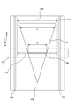
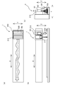
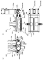
- FIG. 3 It is a conceptual diagram which shows the coating device which concerns on one Embodiment of this invention. It is sectional drawing which shows the pump and discharge width variable apparatus which are employ
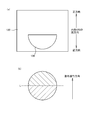
- (A) is sectional drawing of the discharge variable width apparatus shown in FIG. 3
- (b) is a bottom view. It is explanatory drawing which shows the relationship between the surrounding wall of the inner cylinder part in the variable discharge width apparatus shown in FIG. 3, and the discharge port formed in the outer cylinder part.
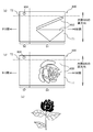
- (A)-(d) is a pattern figure which shows the example of the application pattern by the application
- (A)-(l) is a pattern figure which shows the example of the coating pattern by the coating device shown in FIG. 1, respectively.
- (A)-(g) is a pattern figure which shows the example of the application
- (A), (e) is a developed view of the main part of the inner cylinder according to the modification, and (b) to (d) and (f) to (h) are respectively shown in (a) and (e). It is the pattern figure which showed the example of the application
- (A)-(o) is the pattern figure which showed the example of the application
- (A) to (k) are pattern diagrams showing examples of application patterns that can be applied using the inner cylinder according to FIG.
- (A), (c), (e) is a top view of the application
- (A), (c), (e) is a top view of the application
- (A), (c), (e) is a top view of the application
- FIG. 14 is an apparatus configuration diagram showing a coating apparatus according to a modification, and (b) to (d) are coatings in the first stage, the second stage, and the third stage of coating by the coating apparatus according to (a).
- FIG. It is an apparatus block diagram which shows the structure of the coating device which concerns on a modification, (a) is a top view, (b) is a front view, (c) is a side view. It is an apparatus block diagram which shows the structure of the coating device which concerns on a modification, (a) is a top view, (b) is a front view, (c) is a side view.
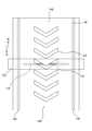
- FIG. 24 It is a front view which shows the nozzle which concerns on a modification.
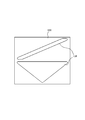
- A is a longitudinal cross-sectional view which shows schematic structure of the discharge width variable apparatus based on a prior art
- (b) is a cross-sectional view of the said discharge width variable apparatus.
- A) is a longitudinal cross-sectional view showing a schematic configuration of the discharge width variable device shown in FIG. 24 with a nozzle attached
- (b) is a cross-sectional view of the discharge width variable device.
- (b) is a developed view of the inner cylinder according to the modified example of (a)
- (c) is an expanded view of the inner cylinder according to (b).
- It is a pattern diagram which shows an example of the discharge pattern at the time of using.
- (A) is an expanded view of the inner cylinder which concerns on a modification
- (b) is a pattern figure which shows the discharge pattern formed using the inner cylinder which concerns on (a).
- the coating apparatus 10 discharge apparatus
- the variable discharge width apparatus 100 can have a configuration in which the discharge width variable device 100 is attached to the industrial robot 20, or a configuration in which the dispensing width device 100 is installed on the conveyor 200 as shown in FIG.
- the coating apparatus 10 can have a configuration in which the discharge width variable device 100 is attached to the industrial robot 20, or a configuration in which the dispensing width device 100 is installed on the conveyor 200 as shown in FIG.
- the embodiment described below first, an example in which the variable discharge width device 100 is installed in the industrial robot 20 as shown in FIG. 1 will be described.
- the coating device 10 includes an industrial robot 20 (moving device), a uniaxial eccentric screw pump 50 (hereinafter also simply referred to as “pump 50”), a discharge width varying device 100, and a control device 170. And.
- the industrial robot 20 is configured by a robot arm or the like.
- a pump 50 is attached to the tip of the arm 22 of the industrial robot 20, and the pump 50 is applied to an object (application object W) to be discharged and applied by operating the industrial robot 20. Can be moved.
- the pump 50 is a device (fluid supply device) provided to pump the fluid from the outside.
- the pump 50 is a so-called rotary displacement pump, and has a configuration in which a stator 66, a rotor 72, a power transmission mechanism 78, and the like are accommodated in a casing 52 as shown in FIG.
- the casing 52 is a metal-made cylindrical member, and a discharge port 54 is provided on one end side in the longitudinal direction.
- a discharge width varying device 100 which will be described in detail later, is attached to the end portion on the side where the discharge port 54 is provided.
- a suction port 64 is provided in the outer peripheral portion of the casing 52. The suction port 64 communicates with the internal space of the casing 52 at the intermediate portion 60 located at the intermediate portion in the longitudinal direction of the casing 52.
- the stator 66 is a member having a substantially cylindrical outer shape formed of an elastic body such as rubber or resin.
- the stator 66 is accommodated in a stator attachment portion 56 located at a position adjacent to the discharge port 54 in the casing 52.
- the outer diameter of the stator 66 is substantially the same as the inner diameter of the stator attachment portion 56. Therefore, the stator 66 is mounted such that the outer peripheral wall thereof is in close contact with the inner peripheral wall of the stator mounting portion 56. Further, one end of the stator 66 is sandwiched between the end portions of the casing 52 by the variable discharge width device 100 described in detail later.
- the inner peripheral wall 70 of the stator 66 has a single-stage or multi-stage female screw shape with n strips.
- the stator 66 has a multistage female screw shape with two threads. More specifically, a through hole 68 extending along the longitudinal direction of the stator 66 and twisted at the above-described pitch is provided inside the stator 66.
- the through hole 68 is formed so that its cross-sectional shape (opening shape) is substantially oval when viewed in cross section at any position in the longitudinal direction of the stator 66.
- the rotor 72 is a metal shaft, and has a single-stage or multi-stage male screw shape with n-1 strips.
- the rotor 72 has a male screw shape that is eccentric by one thread.
- the rotor 72 is formed so that the cross-sectional shape thereof becomes a substantially perfect circle when viewed in cross section at any position in the longitudinal direction.
- the rotor 72 is inserted into the through hole 68 formed in the stator 66 described above, and can be freely eccentrically rotated inside the through hole 68.
- the outer peripheral wall 74 of the rotor 72 and the inner peripheral wall 70 of the stator 66 are brought into close contact with each other at their tangent lines, and the inner peripheral wall 70 of the stator 66 and the outer peripheral wall of the rotor 72 are in contact with each other.
- a fluid conveyance path 76 is formed therebetween.
- the fluid conveyance path 76 extends in a spiral shape in the longitudinal direction of the stator 66 and the rotor 72.
- the fluid conveyance path 76 advances in the longitudinal direction of the stator 66 while rotating in the stator 66. Therefore, when the rotor 72 is rotated, the fluid is sucked into the fluid conveyance path 76 from one end side of the stator 66 and is transferred toward the other end side of the stator 66 in a state of being confined in the fluid conveyance path 76. It is possible to discharge at the other end side of the stator 66.
- the pump 50 of the present embodiment can pump the fluid sucked from the suction port 64 by rotating the rotor 72 in the forward direction and discharge the fluid from the discharge port 54 toward the discharge width varying device 100 described in detail later. It is possible.
- the power transmission mechanism 78 is for transmitting power from the pump driver 96 provided outside the casing 52 to the rotor 72 described above.
- the power transmission mechanism 78 includes a power transmission unit 80 and an eccentric rotation unit 82.
- the power transmission unit 80 is provided on one end side in the longitudinal direction of the casing 52.
- the eccentric rotating part 82 is provided in an intermediate part 60 formed between the power transmission part 80 and the stator mounting part 56.
- the eccentric rotating part 82 is a part that connects the power transmission part 80 and the rotor 72 so that power can be transmitted.
- the eccentric rotating part 82 has a connecting shaft 88 constituted by a conventionally known coupling rod, a screw rod or the like, and connecting bodies 94, 98 constituted by a conventionally known universal joint or the like. Therefore, the eccentric rotating unit 82 can transmit the rotational power generated by operating the pump driving machine 96 to the rotor 72 and rotate the rotor 72 eccentrically.
- the discharge width variable device 100 is capable of discharging the fluid pumped by the pump 50 with a predetermined discharge width. As shown in FIG. 2, the variable discharge width device 100 is connected to the end of the pump 50 described above on the discharge port 54 side. As shown in FIGS. 3 and 4, the discharge width varying device 100 includes a casing 110, an inner cylinder 130, a nozzle 150, and a drive mechanism unit 160 (drive device).
- the casing 110 is hollow and has a cylindrical outer cylinder part 112 (outer cylinder / first structure) and a drive mechanism installation part 114.
- the outer cylinder portion 112 is a cylindrical portion that houses the inner cylinder 130 (second structure), and includes an outer cylinder peripheral portion opening 116 (first opening) and an introduction port 118.
- the drive mechanism installation part 114 is a part in which the components that make up the drive mechanism part 160 are accommodated as will be described in detail later.
- the outer cylinder peripheral part opening 116 provided in the outer cylinder part 112 is provided in the discharge port formation part 122 which makes a part of the peripheral wall 120 of the outer cylinder part 112.
- the outer cylinder peripheral part opening 116 is comprised by the slit-shaped opening, and connects the inside and outside of the outer cylinder part 112. As shown in FIG.
- the outer cylinder peripheral opening 116 is formed so as to extend linearly in the axial direction of the outer cylinder 112, in other words, in a direction (crossing direction) intersecting the circumferential direction of the outer cylinder 112.
- a nozzle 150 which will be described in detail later, is attached to the outer cylinder peripheral opening 116.
- the introduction port 118 is for connecting the discharge port 54 of the pump 50 described above, and is formed in the introduction port forming portion 124 provided on the peripheral wall 120 of the outer cylinder portion 112.
- the introduction port 118 is provided so as to face (adapt) an inner cylinder peripheral portion opening 138 provided in the inner cylinder 130 described in detail later.
- the inner cylinder 130 is housed in an outer cylinder inner space 126 formed inside the outer cylinder portion 112 and is a hollow cylinder having an outer diameter that is substantially the same as the inner diameter of the outer cylinder inner space 126. .
- the inner cylinder 130 is pivotally supported by bearings 132 and 134 at one end side (base end 130a side) and the other end side (connection end 130b side). That is, the inner cylinder 130 is movable relative to the outer cylinder portion 112 by rotation.
- the inner cylinder 130 has a connection end 130 b protruding toward the drive mechanism installation portion 114 formed on one end side of the casing 110, and is connected to the drive mechanism portion 160.
- An inner cylinder peripheral opening 138 (second opening) is formed in the peripheral wall 136 of the inner cylinder 130 so as to communicate between the inside and the outside.
- the inner cylinder peripheral opening 138 is provided at a position facing (facing) the introduction port 118 provided in the outer cylinder 112.
- the inner cylinder peripheral opening 138 is formed such that the opening width d (the length of the inner cylinder 130 in the generatrix direction) continuously changes in the circumferential direction of the inner cylinder 130.
- the inner cylinder peripheral opening 138 has a substantially isosceles triangular opening shape when the inner cylinder 130 is expanded.
- a non-opening 140 is provided at a position deviated in the circumferential direction of the inner cylinder 130 with respect to the inner cylinder peripheral opening 138. Further, as shown in FIG. 5, the opening width d of the inner cylinder peripheral portion opening 138 is smaller than the opening width s of the outer cylinder peripheral portion opening 116 provided in the outer cylinder portion 112 in any part.
- a fluid reservoir 142 for introducing the fluid pumped by the pump 50 is provided inside the inner cylinder 130 (internal space). That is, the inner cylinder 130 is located on the fluid storage part 142 side with respect to the outer cylinder part 112.
- O-rings 144, 146 are provided over the entire circumference of the inner cylinder 130 at the position on the base end 130 a side and the position on the connection end 130 b side with respect to the inner cylinder peripheral opening 138. Is provided.
- the O-rings 144 and 146 are for making a liquid-tight state between the peripheral wall 136 of the inner cylinder 130 and the inner peripheral wall 128 of the outer cylinder portion 112. Therefore, the fluid introduced into the fluid reservoir 142 of the inner cylinder 130 leaks into the region on the base end 130a side and the connection end 130b side of the inner cylinder 130 from the position where at least the O-rings 144 and 146 are provided. do not do.
- the nozzle 150 is attached so as to protrude outward in the radial direction of the outer cylinder portion 112 in the outer cylinder peripheral portion opening 116 of the outer cylinder portion 112 constituting the casing 110 described above.
- the nozzle 150 is a member having an opening area having a shape corresponding to the outer cylinder peripheral opening 116.
- a plurality of partitions 152 are provided inside the nozzle 150 in the longitudinal direction of the nozzle 150.
- the opening area of the nozzle 150 is partitioned so that the partition areas 154 are arranged in the longitudinal direction of the nozzle 150.
- each partition region 154 is a substantially square shape, but can be a substantially round shape, a substantially triangular shape, or a substantially polygonal shape.
- the partition 152 is formed to extend linearly from the opening end side of the nozzle 150 to the outer cylinder peripheral opening 116 side.
- the drive mechanism unit 160 includes a drive unit 162 configured by a motor, a first bevel gear 164 connected to the rotation shaft of the drive unit 162, and a connection end of the inner cylinder 130. And a second bevel gear 166 connected to the 130b side.
- the driving machine 162 is installed so that the rotating shaft protrudes into the driving mechanism installation part 114 of the casing 110. Further, the first bevel gear 164 and the second bevel gear 166 are accommodated in the drive mechanism installation portion 114, and both mesh with each other. Therefore, the inner cylinder 130 can be rotated in the outer cylinder portion 112 by operating the driving device 162. Further, by controlling the rotation amount and the rotation direction of the driving machine 162, the rotation amount of the inner cylinder 130 can be adjusted and the rotation direction can be changed.
- variable discharge width device 100 includes an outer cylinder peripheral opening 116 provided in the outer cylinder 112, and an inner cylinder peripheral opening 138 provided in the inner cylinder 130.
- a communication region 148 in which the two communicate with each other is formed in the overlapping portion.
- discharge width the width D of the communication region 148 (hereinafter referred to as “discharge width”).
- D discharge width
- the discharge width D of the communication region 148 gradually increases, and when the inner cylinder 130 is rotated in the direction of arrow B opposite to this, the discharge width D Gradually shrinks. Further, when the inner cylinder 130 is rotated to a position where the non-opening 140 overlaps with the outer cylinder circumferential opening 116, the outer cylinder circumferential opening 116 is closed by the non-opening 140, that is, the discharge width D is zero. As a result, the fluid cannot be discharged.
- the control device 170 controls position control for controlling the relative position of the pump 50 with respect to the coating object W, speed control for controlling the moving speed of the pump 50 with respect to the coating object W, and controls the amount of fluid supplied to the coating width variable device 100.
- the supply amount control to be performed, the discharge width control to control the discharge width D of the fluid discharged from the discharge width variable device 100, and the like can be performed alone or in combination.
- the control device 170 includes a discharge width control unit 171, a position control unit 172, a speed control unit 173, a supply amount control unit 174, and a synchronization unit 175.
- the control device 170 controls the position (position control) of the pump 50 attached to the tip of the arm 22 by adjusting the position of the industrial robot 20, the angle of the arm 22, the amount of expansion / contraction, and the like by the position control means 172. be able to. Further, the control device 170 can control the moving speed of the pump 50 with respect to the coating object W (speed control) by adjusting the moving speed of the industrial robot 20 and the arm 22 by the speed control means 173.
- control device 170 can control the supply amount of the fluid to the discharge width variable device 100 (supply amount control) by controlling the rotation speed of the pump driving machine 96 with the supply amount control means 174. . Furthermore, the control device 170 adjusts the rotation amount and the rotation direction of the driving device 162 of the variable discharge width device 100 by the discharge width control means 171, and the outer cylinder peripheral portion opening 116 provided in the outer cylinder portion 112 and the inner cylinder. The discharge width D can be increased or decreased by changing the relative position with the inner cylinder peripheral opening 138 provided at 130. Therefore, the control device 170 can control the discharge width D of the fluid (discharge width control) by controlling the operation of the driving device 162.
- control device 170 can synchronize the position control, the speed control, the supply amount control, and the discharge width control described above by the synchronization unit 175. Thereby, applying a fluid with a desired application width to a desired position with respect to the application object W, applying a fluid at a desired speed, gradually changing the discharge width during the application operation, In addition, the fluid can be applied in a desired shape.
- the operation control performed by the control device 170 when the fluid is applied to the coating object W by the coating device 10 will be described with reference to the case where coating is performed using the coating pattern illustrated in FIG. This will be described in detail with reference to the flowchart of FIG.
- the fluid is adjusted while adjusting (changing) the discharge width D at intermediate positions P1 and P2 provided from the start point S to the end point E.
- Apply Specifically, in the section from the starting point S to the intermediate position P1, the discharge width D is adjusted to D1, and the flow rate is controlled by moving the pump 50 and the discharge width varying device 100 by position control while performing supply amount control. Apply animals.
- the discharge width D is changed to D2, and the application is advanced to the intermediate position P2 under the supply amount control and the position control.
- the discharge width D is changed to D1 again, and the application is advanced to the end point E under the supply amount control and the position control.
- step 1 the controller 170 indicates a position (starting point S) where the application starts. Based on the information, the industrial robot 20 and the arm 22 are moved, and the discharge width varying device 100 attached to the tip of the pump 50 is moved to the position of the start point S. Thereafter, when the control flow proceeds to step 2, the control device 170 adjusts the rotation amount and the rotation direction of the driving device 162 and rotates the inner cylinder 130 so that the discharge width D matches the desired application width. Move. In the case of applying with the application pattern of FIG. 8A, if the variable discharge width device 100 exists at the starting point S, the discharge width D is adjusted to D1. Further, when the application of the fluid proceeds and reaches the intermediate position P1 or the intermediate position P2, the discharge width D is adjusted to D2 or D1.
- the discharge width D when the discharge width D is adjusted in step 2, the discharge amount of the fluid changes, so it is also necessary to adjust the supply amount of the fluid to the discharge width variable device 100.
- the discharge width D when the discharge width D is expanded, the fluid discharge amount increases, so the rotational speed of the rotor 72 in the pump 50 is increased so that the fluid supply amount to the discharge width variable device 100 increases.
- the discharge width D when the discharge width D is reduced, the discharge amount of the fluid is reduced, so that the rotational speed of the rotor 72 needs to be reduced. Therefore, when the discharge width D is adjusted in step 2, the supply amount of the fluid to the discharge width variable device 100 is adjusted under the supply amount control in step 3 thereafter.
- step 4 the industrial variable robot 20 and the arm 22 are moved to move the variable discharge width device 100 attached to the tip of the pump 50 according to the coating pattern. Thereby, the fluid is discharged by the discharge width D set in step 2 and applied to the application target W.
- step 5 After the movement of the variable discharge width device 100 is started in step 4, it is determined in step 5 that the variable discharge width device 100 has reached the position where the discharge width D should be changed, specifically, the intermediate position P1 or the intermediate position P2. If confirmed, the control flow is returned to step 2. When the control flow returns to step 2, the coating operation is performed after changing the discharge width D according to the flow of steps 2 to 4 described above.
- step 5 if it is determined in step 5 that the position of the variable discharge width device 100 is not the discharge width change position (intermediate positions P1, P2), the control flow proceeds to step 6.
- step 6 it is confirmed whether or not the variable discharge width device 100 has reached the end point E.
- the control flow is returned to step 4 and the coating operation is continued.
- step 6 when it is confirmed in step 6 that the end point E has been reached, the control flow proceeds to step 7 and the coating operation is stopped. Specifically, the movement of the variable discharge width device 100 and the like and the supply of the fluid by the pump 50 are stopped, and the discharge width D is switched to zero. Thereby, application
- variable discharge width device 100 included in the coating apparatus 10 of the present embodiment moves the outer cylinder portion 112 and the inner cylinder 130 relative to each other, thereby causing the outer cylinder peripheral portion opening 116 and the inner cylinder peripheral portion opening 138 to move. It is possible to adjust the width (length in the crossing direction) of the communication region 148 formed by the overlap and the position where the communication region 148 is formed.
- the nozzle 150 is provided in the outer cylinder peripheral opening 116, the fluid can be discharged at a position very close to the workpiece to be discharged. Therefore, even when a fluid is applied with a wide application width, the fluid can be applied with high accuracy without involving air between the applied fluid and the workpiece.
- a device such as a device capable of blowing air or the like is provided, and measures such as spraying on the applied fluid are taken.
- a device such as the above-described air blowing device is not required, and the device configuration and operation control can be simplified correspondingly.
- the nozzle 150 has an opening area divided into a plurality of partition areas 154 by a plurality of partitions 152.
- the fluid flowing into the nozzle 150 through the outer cylinder peripheral opening 116 reaches the tip of the nozzle 150 without being spread in the width direction within the nozzle 150 and is discharged. Therefore, according to the discharge width variable apparatus 100, it is possible to apply the fluid to the workpiece in a well-defined shape as expected.
- the inner cylinder 130 as the second structural body is disposed inside the outer cylindrical portion 112 as the first structural body, and the inner cylinder 130 is rotated to relatively move both of them.
- the width D can be adjusted. Therefore, according to the discharge width varying device 100, the width and position of the communication region 148 through which the fluid is discharged can be adjusted by controlling the amount and direction of rotation of the inner cylinder 130 with respect to the outer cylinder portion 112. .
- this invention is not limited to this. That is, instead of the outer cylinder portion 112 and the inner cylinder 130, for example, flat plates are provided as the first component and the second component, and openings instead of the outer cylinder peripheral portion opening 116 and the inner cylinder peripheral portion opening 138 are provided on these flat plates. Can be provided. Also in the case of such a configuration, the discharge width D can be adjusted by relatively moving the flat plates corresponding to the first configuration body and the second configuration body.
- the size of the partition region 154 formed on the nozzle 150 described above can be adjusted to an appropriate size in consideration of various factors. For example, the viscosity of the fluid to be discharged is taken into consideration.
- the size of the partition area 154 can be adjusted. More specifically, the nozzle 150 is preferably provided with a partition 152 such that the lower the viscosity of the fluid, the smaller the opening area of the partition region 154. By doing in this way, it becomes possible to suppress dripping when the fluid to be handled has a low viscosity. Moreover, when the fluid handled is high viscosity, it can suppress that a fluid clogs in each division area
- the opening area of the partition region 154 may be different between the width end sides and the center side of the nozzle 150.
- the opening area of each partition region 154 can be optimized while taking into account disturbances such as the characteristics of the fluid and the pressure fluctuation of the supplied fluid, and the control characteristics of the discharge width D can be further improved.
- the partition 152 is formed from the distal end side (opening end side) to the position reaching the proximal end side (outer cylinder peripheral portion opening 116 side). Therefore, the fluid led out through the communication region 148 is surely introduced into the partition region 154 existing at the position to be discharged while suppressing the flow into the partition region 154 at the position where the fluid should not be discharged. Can be discharged. Thereby, the discharge width D and the discharge position of the fluid discharged from the nozzle 150 can be made as expected.
- the partition 152 extends linearly from the distal end side to the proximal end side of the nozzle 150. Therefore, the fluid can be rectified and discharged in the nozzle 150 while preventing the fluid from being clogged in the nozzle 150.
- the partition 152 has a linearly extending shape is shown, but the present invention is not limited to this, and may be a bent shape or the like.
- the variable discharge width device 100 changes the discharge width D by rotating the inner cylinder 130, and almost no change in the internal volume due to the change of the discharge width D occurs. Thereby, it is possible to minimize the occurrence of fluctuations in the discharge pressure with the change in the discharge width D. Moreover, in the coating apparatus 10 of this embodiment, since the pump 50 is employed as the fluid supply device, the fluid can be supplied to the variable discharge width device 100 with a substantially constant supply amount and supply pressure. Therefore, even if the coating device 10 continuously or intermittently changes the coating width (discharge width D), the thickness (film thickness) of the fluid applied to the coating object W and the adhesion of the fluid Fluctuations in coating characteristics such as properties hardly occur, and a fluid can be applied with a constant quality.
- the discharge width varying device 100 includes an O-ring 144, 146 provided at a position closer to the base end 130a side and the connection end 130b side than the inner cylinder peripheral opening 138, so that the inner wall 130 of the inner cylinder 130 and the inner cylinder part 112 can be The space between the peripheral wall 128 is liquid-tight. Further, in the discharge width variable device 100, the inlet 118 for introducing the fluid supplied by the pump 50 is provided at a position facing the inner cylinder peripheral opening 138 in the peripheral wall 136 of the outer cylinder 112. . Furthermore, the opening width d of the inner cylinder peripheral portion opening 138 is smaller than the opening width s of the outer cylinder peripheral portion opening 116 provided in the outer cylinder portion 112 in any part.
- the configuration in which the O-rings 144 and 146 are provided on the inner cylinder 130 is illustrated, but the present invention is not limited to this, and a sealing member such as an O-ring is provided on the outer cylinder portion 112 side. It is good also as a structure which provided.
- the discharge width varying device 100 is provided with O-rings 144 and 146 in order to make the space between the inner cylinder 130 and the outer cylinder portion 112 liquid-tight, but instead of the O-rings 144 and 146, or In addition to the O-rings 144 and 146, other sealing members such as a burr seal and a lip seal may be provided.
- the opening width d of the inner cylinder peripheral opening 138 is formed to be smaller than the opening width s of the outer cylinder peripheral opening 116 provided in the outer cylinder 112 has been described. d and s may be the same.
- the coating apparatus 10 of this embodiment can be implemented in a state where position control, speed control, supply amount control, and discharge width control are synchronized, and the size of the discharge width D of the fluid discharged for application,
- the change speed of the discharge width D, the supply amount (supply speed) of the fluid from the pump 50 to the discharge width variable device 100, the positional relationship between the discharge width variable device 100 and the application object W, and the movement of the discharge width variable device 100 It is possible to adjust so as to be in an appropriate state according to the speed. Thereby, for example, as shown in FIG. 8A, it is possible to apply the fluid with different widths depending on the portion of the application target W.
- the operation in the case where the fluid is applied with the application pattern shown in FIG. 8A is exemplified.
- the application device 10 discharges according to the position, moving speed, and the like of the variable discharge width device 100.
- the width D and the like in addition to the coating pattern of FIG. 8A, the coating pattern shown in FIGS. 8B to 8D and the coating pattern (patterns shown in FIGS. 9A to 9L)
- the fluid can be applied to the application object W by various application patterns.
- the outer cylinder peripheral opening 116 formed in the outer cylinder part 112 is formed by a slit extending linearly in the width direction of the outer cylinder part 112. It is not limited to this. Specifically, instead of the outer cylinder periphery opening 116, slits provided intermittently in the width direction of the outer cylinder part 112, slits formed so as to be inclined, slits having a curved portion, and the opening shape is circular. Alternatively, an oval, rectangular or polygonal opening may be provided. By adopting such a configuration, it becomes possible to discharge the fluid in various forms, and the fluid can be applied by various application patterns.
- the nozzle 150 may be formed in a shape such as an inclined shape or a curved shape.
- the opening shape of the inner cylinder peripheral opening 138 formed in the inner cylinder 130 is not limited to the above-described one as in the case of the outer cylinder peripheral opening 116. It is possible to change to various shapes according to this. That is, the inner cylinder peripheral portion opening 138 may be formed so that the discharge width D in the axial direction and the opening position in the axial direction are changed in the circumferential direction of the inner cylinder 130. Any thing is acceptable.
- the fluid can be applied to the application object by application patterns (patterns) as shown in FIGS. 10 (a) to 10 (g), for example.
- the inner cylinder peripheral opening 138 having a shape as shown in FIG. 11 is provided in the peripheral wall 136, the width and position of the communication region 148 can be adjusted by rotating the inner cylinder 130 in synchronization with the coating speed. It changes sequentially and a fluid can be apply
- the inner cylinder peripheral portion opening 138 is formed in a character shape and the movement of the discharge width varying device 100 and the rotation of the inner cylinder 130 are synchronized, for example, as shown in FIG. Is possible.
- the movement of the variable discharge width device 100 and the rotation of the inner cylinder 130 are synchronized, for example, as shown in FIG.
- the fluid can be applied to the workpiece in a pattern as shown in (b) to (d) or a pattern as shown in FIGS. 13 (f) to (h).
- the inner cylinder peripheral opening 138 is shaped as shown in FIG. 14, and the discharge width control is performed while the position of the coating apparatus 10 in the two-dimensional direction is controlled, so that various types as shown in FIG. 15 and FIG. Fluids can be applied in a variety of two-dimensional patterns.
- the position of the coating apparatus 10 is three-dimensionally controlled so as to be three-dimensionally shown in FIGS.
- the fluid can be applied in a laminated pattern.
- the coating apparatus 10 can be attached to the industrial robot 20 to move the variable discharge width device 100 in three dimensions with respect to the workpiece.
- the present invention is limited to this. It is not something.
- the coating apparatus 10 has a configuration in which a conveyor 200 that transports a workpiece to be coated is provided as a moving device, and the discharge width variable device 100 is installed at a position away from the conveyor 200. It is also good. Also in the case of such a configuration, the position control by adjusting the operation of the conveyor 200 and the discharge width control by the discharge width variable device 100 are synchronized by the control device 170, so that the fluid is applied to the workpiece with a desired application pattern. It is possible to apply to.
- the discharge width varying device 100 provided in the coating device 10 does not have to be single, and a plurality of devices may be provided as shown in FIG.
- a plurality (three in the example of FIG. 20) of variable discharge width devices 100 are arranged in parallel in the conveying direction of the conveyor 200. Accordingly, the fluid is applied by the discharge width varying device 100 arranged on the upstream side of the workpiece conveyance direction, and another fluid is applied to the same or different by the discharge width varying device 100 arranged on the downstream side. It is possible to apply the patterns one after another (see FIGS. 20B to 20D). It is also possible to make the application pattern applied by the upstream discharge variable device 100 different from the application pattern applied by the downstream discharge variable device 100. By doing so, it is possible to form various patterns (monkeys in the illustrated example) as shown in FIG.
- the coating apparatus 10 is movable in a substantially horizontal direction (X and Y directions in the figure) and a height direction (Z direction in the figure) with respect to the work itself or a table on which the work is mounted.
- the moving device 210 may include the variable discharge width device 100.
- the coating apparatus 10 is moved while applying the fluid by moving the coating apparatus 10 in the X and Y directions with respect to the workpiece along a predetermined locus (see the two-dot chain line in FIG. 21A).
- the distance from the workpiece can be maintained at a predetermined distance, and the thickness of the applied fluid can be adjusted.
- a scanner 212 that scans the relative position of the workpiece to which the fluid is applied, the shape of the workpiece, and the like is mounted on the moving device 210 together with the variable discharge width device 100. It is good to have done. With this configuration, it is possible to apply the fluid to the workpiece with an appropriate width and thickness while detecting the relative position to the workpiece to be applied and the shape of the workpiece by the scanner 212.
- a fluid is applied to a workpiece curved in a shape as shown by shading in the figure.
- the relative position with respect to the workpiece and the shape of the workpiece are measured by the scanner 212 while simultaneously moving the variable discharge width device 100 and the scanner 212 in the X direction. That is, the change in the width of the work accompanying the movement in the X direction and the locus of the center of the work are measured.
- the discharge width variable device 100 is grasp how the discharge width variable device 100 should be moved in the X direction while changing the discharge position (trajectory) in the Y direction.
- the discharge variable width device 100 and the scanner 212 are moved again in the X direction on the workpiece.
- the discharge width variable device 100 is calculated based on the relative position of the workpiece, the discharge width D, and the locus, which are measured in advance, taking into account the installation interval in the X direction of the discharge width variable device 100 and the scanner 212.
- the adjustment of the discharge width D and the position adjustment of the discharge width variable device 100 in the Y direction are performed. Thereby, a fluid can be apply
- the fluid is applied to a plurality of workpieces arranged on a table with different thicknesses by the coating device 10 including the moving device 210 and the scanner 212 as in the case shown in FIG. 21. It is an example to apply. Also in this example, first, the variable discharge width device 100 and the scanner 212 are simultaneously moved in the X direction, and the shape and relative position of each workpiece placed on the table are measured by the scanner 212. Thereby, it is grasped at what discharge width D and discharge position the fluid should be discharged. Thereafter, the variable discharge width device 100 and the scanner 212 are moved again in the X direction on the workpiece.
- the discharge width D in the variable discharge width device 100 is adjusted and the position of the variable discharge width device 100 in the Y and Z directions is adjusted based on the previously derived measurement result, and a predetermined locus (FIG. 22 (a) (see the two-dot chain line), and apply the fluid.
- a fluid can be apply
- the discharge variable width apparatus 100 exemplified in the above-described embodiment and modification can discharge the fluid by causing the nozzle 150 to reach a position very close to the workpiece to be coated. Therefore, as described above, in the case where the discharge width varying device 100 is arranged in parallel in the workpiece moving direction and the fluid is applied over a plurality of layers, the nozzle 150 of the discharge width varying device 100 arranged on the upstream side.
- the height of the nozzle 150 of the discharge width varying device 100 arranged at a position adjacent to the downstream side with respect to the height of the nozzle is provided at a position separated upward by an amount corresponding to the thickness of the fluid applied previously. desirable.
- the coating device 10 and the variable discharge width device 100 described above can apply the fluid in various coating patterns by sequentially changing the discharge width D of the fluid. Therefore, the present invention can be applied to, for example, food production apparatuses, tactile printers (printers capable of drawing three-dimensional signs such as Braille and dotted figures), three-dimensional molding apparatuses, road marking forming apparatuses (road printers), and the like.
- food production apparatus in the coating apparatus 10 shown in FIG. 20, food such as cookies can be formed into a desired shape by using a dough such as cookies as a fluid.
- a coating device 10 and a variable discharge width can be used as a device for forming irregularities forming Braille and dotted figures by applying and curing a curable fluid such as an adhesive on the surface of a sheet of paper or a plate.
- the apparatus 100 can be used.
- a curable fluid is applied and cured in a linear or planar desired shape on the surface of a paper or plate using the coating device 10 or the variable discharge width device 100, a tactile map or the like can be obtained.
- a three-dimensional sign can be formed.
- the coating apparatus 10 and the discharge device are used as a three-dimensional modeling apparatus that creates a three-dimensional (three-dimensional) model by applying and curing a curable fluid sequentially on the basis of 3D CAD data or 3DCG data.
- the variable width device 100 can be used.
- the application device 10 and the discharge width variable device 100 are mounted on a moving device that can move on a road such as a vehicle, and an application material for forming a road marking marked on the road is operated on the road while operating the moving device.
- the coating device 10 and the variable discharge width device 100 can be used as a road marking forming device (road printer).
- the coating device 10 (discharge device) can be used not only for the purpose of applying the coating material on the surface but also for the purpose of discharging the coating material into the liquid.
- the nozzle 150 of the coating apparatus 10 is inserted in a direction (Z-axis direction) from the opening side to the bottom side of the container V containing the predetermined liquid L1.
- the length of the nozzle 150 is preferably a length that reaches from the opening side of the container V to the vicinity of the bottom as shown in FIGS.
- the coating apparatus 10 moves the nozzle 150 inserted into the liquid L1 relative to the container V in the Z-axis direction as shown in FIGS. A liquid L2 different from L1 is discharged. Thereby, as shown in FIGS. 26C and 26D, the liquid L2 can be discharged into the liquid L1. Further, by synchronizing the movement of the nozzle 150 in the Z direction and the adjustment of the discharge width (length in the X direction in the drawing) of the liquid L2 by the discharge width varying device 100, a desired pattern (shape) is formed in the liquid L1. ) Can be discharged with the liquid L2.
- the thickness of the pattern of the liquid L2 formed in the liquid L1 by the liquid L2 (the length in the Y direction in the drawing). Can be changed sequentially. Specifically, as shown in FIG. 26 (d), the thickness of the pattern of the liquid L2 can be changed in each part. Thereby, the liquid L2 can be discharged in three dimensions into the liquid L1.
- the relative movement of the nozzle 150 in the Z-axis direction with respect to the container V can be realized by moving either one or both of the nozzle 150 side and the container V side in the Z-axis direction. Further, when the nozzle 150 is relatively moved in the Z-axis direction with respect to the container V, the liquid L2 is twisted spirally in the liquid L1 by rotating either one or both of the nozzle 150 and the container V around the Z-axis. It becomes possible to discharge so that it may become a shape.
- the liquids L1 and L2 can be selected as appropriate. Specifically, for example, by employing a transparent jelly as the liquid L1, and employing another jelly colored as the liquid L2, a jelly having a pattern drawn on the inside can be provided. Further, by adopting a gel-like cosmetic as the liquid L1 and using another cosmetic or other material as the liquid L2, a cosmetic having an excellent design with a pattern drawn therein can be provided.
- the discharge width varying device 100 described above has one outer cylinder portion 112 and one inner cylinder 130, but may be one in which either one or both of the inner and outer cylinders are provided. .
- a coating apparatus 500 and a variable discharge width apparatus 510 shown in FIG. 27 can be provided as a modification of the coating apparatus 10 and the variable discharge width apparatus 100.
- the coating device 500 has a structure in which two pumps 50 (hereinafter also referred to as “first pump 50a” and “second pump 50b” as necessary) are connected to the discharge width variable device 510.
- the variable discharge width device 510 is configured to include two structures corresponding to the variable discharge width device 100 described above in parallel.
- variable discharge width device 510 includes a first variable width mechanism 520 ⁇ / b> A, a second variable width mechanism 520 ⁇ / b> B, and a communication path 530, and a nozzle 150 is attached to a terminal portion of the communication path 530. .
- the first variable width mechanism 520A and the second variable width mechanism 520B are mechanisms that operate on the same operating principle as the variable discharge width device 100. Since the configurations of the first variable width mechanism 520A and the second variable width mechanism 520B are common, both will be collectively referred to as the variable width mechanism 520 below. Further, the configuration corresponding to the first width variable mechanism 520A is illustrated with an A added to the end of the reference numeral, and the configuration corresponding to the second width variable mechanism 520B is illustrated with an additional B added to the end of the reference numeral. To do.
- the variable width mechanism 520 is hollow and has a cylindrical outer cylinder 522 (outer cylinder / first structure), an inner cylinder 524, and a drive mechanism section 525. Similar to the above-described variable discharge width device 100, the variable width mechanism 520 adjusts the relative position between the outer cylinder 522 and the inner cylinder 524 in the circumferential direction, so that the communication region is formed by overlapping holes formed in the two. The width and position can be adjusted.
- the outer cylinder 522 corresponds to the outer cylinder portion 112 (outer cylinder / first structure) in the discharge width varying device 100 described above.
- the outer cylinder 522 is a substantially cylindrical cylinder and has an outer cylinder peripheral opening 526 on the outer periphery.
- the outer cylinder periphery opening 526 is a slit-shaped opening and communicates the inside and outside of the outer cylinder 522.
- the outer cylinder peripheral opening 526 is formed so as to extend linearly in the axial direction of the outer cylinder 522, in other words, in a direction intersecting the circumferential direction of the outer cylinder 522 (cross direction).
- the outer cylinder peripheral opening 526 communicates with the communication path 530.
- the outer cylinder 522 is provided with an inlet (not shown) formed so as to communicate with the pump 50. This introduction port corresponds to the introduction port 118 provided in the outer cylinder portion 112 in the discharge width varying device 100 described above.
- the inner cylinder 524 is a member corresponding to the inner cylinder 130 in the discharge width varying device 100 described above, and is accommodated in the outer cylinder 522.
- the inner cylinder 524 is a hollow and cylindrical member having a space into which a fluid can be introduced inside (inner space).
- the inner cylinder 524 is supported so as to be freely rotatable around the axial center position.
- the inner cylinder 524 is connected to the drive mechanism unit 525.
- the drive mechanism unit 525 corresponds to the drive mechanism unit 160 described above, and can rotate the inner cylinder 524.
- the drive mechanism section 525 includes a drive machine 525a configured by a motor, a first bevel gear 525b connected to the rotation shaft of the drive machine 525a, and a second bevel gear 525c connected to the inner cylinder 524.
- a drive machine 525a configured by a motor
- a first bevel gear 525b connected to the rotation shaft of the drive machine 525a
- a second bevel gear 525c connected to the inner cylinder 524.
- an inner cylinder peripheral portion opening 527 (second opening) is formed so as to communicate between the inside and the outside.
- the inner cylinder peripheral opening 527 is formed so that the opening width d and the opening position continuously change in the circumferential direction of the inner cylinder 524, similarly to the inner cylinder peripheral opening 138 in the discharge width varying device 100 described above. Yes. That is, the inner cylinder peripheral opening 527 has a substantially isosceles triangular opening shape in the unfolded state like the inner cylinder peripheral opening 138 shown in FIG. 5, or the one shown in FIG. 11 or FIG. It can be of an appropriate opening shape.
- variable width mechanism 520 rotates the inner cylinder 524 with respect to the outer cylinder 522 and adjusts the positional relationship between them in the circumferential direction, whereby the inner cylinder peripheral opening 527 and the slit-shaped outer cylinder peripheral opening 526 The width and position of the communication area formed by overlapping can be adjusted.
- the first width variable mechanism 520A and the second width variable mechanism 520B are housed in the case 529, respectively.
- the first variable width mechanism 520 ⁇ / b> A and the second variable width mechanism 520 ⁇ / b> B are arranged in the case 529 so that the outer cylinder peripheral openings 526 ⁇ / b> A and 526 ⁇ / b> B face each other.
- Outer cylinder peripheral part opening 526A, 526B is connected with respect to the communicating path 530, respectively.
- the communication path 530 is a path that communicates in three directions, and can be, for example, a path having a substantially T-shaped or a substantially Y-shaped cross section (in the illustrated example, a substantially T-shaped path).
- the communication passage 530 is formed so as to have the same cross-sectional shape as the opening region of the outer cylinder peripheral opening 526A, 526B in each part.
- Outer passages 526A and 526B are connected to two passages (passages 530a and 530b extending in the left-right direction in the illustrated state) among the passages 530a, 530b and 530c extending in three directions constituting the communication passage 530, respectively.
- the remaining one (the passage 530c extending in the vertical direction in the illustrated state) protrudes downward from the bottom surface of the case 529.
- a nozzle 150 is attached to the passage 530c.
- the first pump 50a is connected to the first width varying mechanism 520A. Therefore, in the first variable width mechanism 520A, the width and position of the communication area formed by the overlap between the outer cylinder peripheral opening 526 and the inner cylinder peripheral opening 527 are adjusted, and the first pump 50a is driven in the forward direction. By supplying the fluid to the first width varying mechanism 520A, the fluid can be discharged at an arbitrary application width and application position.
- the second pump 50b connected to the second variable width mechanism 520B has the ability to supply the coating liquid by being driven in the forward direction, like the first pump 50a. It is used as one that exhibits the ability to reversely flow the coating liquid by being driven in the direction. Therefore, in the second variable width mechanism 520B, the communication area formed by the overlap of the outer cylinder peripheral opening 526 and the inner cylinder peripheral opening 527 is adjusted, and the second pump 50b is driven in the reverse direction in this state. Thus, it is possible to draw in the fluid adhering to the communication path 530 and the nozzle 150.
- the fluid is discharged only in the area where the fluid is not discharged on the first variable width mechanism 520A side. Suction can be performed. Accordingly, the fluid can be sucked on the second width variable mechanism 520B side without disturbing the discharge of the fluid in the first width variable mechanism 520A.
- the second variable width mechanism 520B and the second pump 50b are operated while discharging the fluid in a predetermined pattern by operating the first variable width mechanism 520A and the first pump 50a. By doing so, the fluid can be drawn in and dripping can be prevented. Thereby, it becomes possible to further improve the coating quality.
- variable discharge width variable device 600 shown in FIG. Something like that can be provided.
- the variable discharge width device 600 will be described.
- portions common to the discharge width variable device 100 are denoted by the same reference numerals, and detailed description thereof is omitted.
- the discharge width variable device 600 shown in FIG. 28 is provided with a plurality of inner cylinders 610 and 612 (two in the illustrated example) in place of the inner cylinder 130 inside the single outer cylinder portion 112. This is different from the variable width device 100.
- the inner cylinders 610 and 612 are configured to be arranged inside the outer cylinder part 112 in the longitudinal direction of the outer cylinder part 112.
- Inner cylinder periphery openings 620 and 622 are provided on the peripheral walls 614 and 616 of the inner cylinders 610 and 612, respectively. Each of the inner cylinder peripheral openings 620 and 622 can have an appropriate opening shape.
- Inner cylinder peripheral part opening 620,622 is formed so that opening width d and an opening position may change as it progresses in the circumferential direction of inner cylinder 610,612.
- the inner cylinders 610 and 612 are connected to the drive mechanism units 630 and 632, respectively.
- the drive mechanism units 630 and 632 are the same as the drive mechanism unit 160 and the drive mechanism unit 525 described above, respectively.
- variable discharge width variable device 600 In the discharge width variable device 600 described above, an example in which a plurality of inner cylinders (two inner cylinders 610 and 612 in the illustrated example) are provided is shown, but the present invention is not limited to this, In addition to the cylinders 610 and 612, another inner cylinder may be provided. Further, in the variable discharge width device 600, an example in which a plurality of cylinders (inner cylinders 610 and 612) arranged inside the outer cylinder portion 112 is shown, but the present invention is not limited to this. It is good also as what comprised the outer cylinder part 112 by the some cylinder. Furthermore, the outer cylinder portion 112 may be configured by a plurality of cylinders, while the inner cylinders 610 and 612 in the variable discharge width device 600 are plural.
- variable discharge width device 100 described above has a configuration in which a single (single layer) inner cylinder 130 is provided inside the outer cylinder portion 112, but the present invention is not limited to this.
- a multi-layered inner cylinder portion in which a plurality of cylinders similar to the inner cylinder 130 are provided in the radial direction may be provided.
- a variable discharge width apparatus 700 shown in FIG. 29 can be provided as a variation of the above-described variable discharge width apparatus 100.
- the variable discharge width device 700 will be described.
- portions common to the discharge width variable device 100 are denoted by the same reference numerals, and detailed description thereof is omitted.
- a discharge width varying apparatus 700 shown in FIG. 29 is provided with an inner cylinder portion 710 shown with hatching in FIG. 29A instead of the inner cylinder 130 inside a single outer cylinder portion 112. This is different from the variable discharge width device 100 in that respect.
- the inner cylinder portion 710 includes a plurality of outer layer side inner cylinders 712 and inner layer side inner cylinders 714 (two in the illustrated example) having different outer diameters.
- the inner cylinder portion 710 has a nested configuration in which the outer layer side inner cylinder 712 and the inner layer side inner cylinder 714 are overlapped in the radial direction in multiple layers.
- the outer-layer-side inner cylinder 712 is a cylinder whose outer diameter is the same as or slightly smaller than the inner diameter of the outer cylinder part 112, as with the inner cylinder 130, and the axial center position within the outer cylinder part 112. It can be rotated around the center.
- the inner layer side inner cylinder 714 is a cylinder that is equal to or slightly smaller than the inner diameter of the outer layer side inner cylinder 712, and has an axial center position substantially the same as that of the outer layer side inner cylinder 712 inside the outer layer side inner cylinder 712. The center is rotatable.
- the outer layer side inner cylinder 712 is provided with an outer layer side inner cylinder peripheral opening (not shown). Further, the inner cylinder side inner cylinder 714 is also provided with an inner cylinder peripheral part opening 720.
- the outer-layer-side inner cylinder periphery opening and the inner cylinder periphery opening 720 can each have an appropriate opening shape.
- the outer layer side inner cylinder periphery opening and the inner cylinder periphery opening 720 are formed such that the opening width d and the opening position change as the outer layer side inner cylinder 712 and the inner layer side inner cylinder 714 move in the circumferential direction.
- the outer-layer side inner cylinder 712 and the inner-layer side inner cylinder 714 are connected to separate drive mechanism portions 730 and 732, respectively, and can be independently rotated.
- the drive mechanism units 730 and 732 are the same as the drive mechanism unit 160 and the drive mechanism unit 525 described above, respectively.
- one of the outer layer side inner cylinder 712 and the inner layer side inner cylinder 714 is used as one that contributes to the adjustment of the ejection pattern, and the other does not contribute to the adjustment of the ejection pattern. It is possible to use it.
- the opening (either one of the inner cylinder peripheral opening 720 or 722) is the entire area of the outer cylinder peripheral opening 116.
- the rotation position is adjusted so as to be opened.
- an opening is provided at a position where a desired discharge pattern can be achieved by rotation control.
- the rotation position is adjusted so that one of the partial openings 720 and 722) is reached.
- the number of the inner-layer-side inner cylinder 712 and the inner-layer-side inner cylinder 714 can be increased as compared with the case where only one inner cylinder 130 is provided as in the discharge width varying device 100 described above.
- the fluid can be discharged so as to achieve an application pattern (in this modification, the number of patterns equivalent to that provided with two inner cylinders 130).
- one of a plurality of inner cylinders (the outer layer side inner cylinder 712 and the inner layer side inner cylinder 714) is selectively used for forming a discharge pattern.
- the present invention is not limited to this, and two or more of a plurality of inner cylinders may be used in combination for forming an ejection pattern.
- the relative positions of the outer-layer inner cylinder 712 and the inner-layer inner cylinder 714 are controlled by controlling the amount and direction of rotation of the driving machines 734 and 736 (motors) provided in the drive mechanism units 730 and 732.
- the opening area of the inner cylinder part 710 as a whole can be adjusted by adjusting and adjusting the overlapping state of the inner cylinder peripheral part openings 720 and 722. Therefore, in the discharge width variable device 700, a plurality of inner cylinders (the outer layer side inner cylinder 712 and the inner layer side inner cylinder 714) are used in combination for forming a discharge pattern. A fluid can be discharged with a simple discharge pattern.
- the present invention is limited to this. Is not to be done. That is, the outer cylinder portion 112 may have a multi-layer structure while adopting the inner cylinder 130 having a single layer structure. Moreover, it is good also as a structure which provided the multilayer structure also about the outer cylinder part 112, providing the inner cylinder part 710 of a multilayer structure.
- the above-described coating apparatus 10 can discharge a fluid only at the nozzle 150 provided in the variable discharge width apparatus 100, but the present invention is not limited to this.
- the discharge width variable apparatus 900 is provided with another nozzle 910 in addition to the nozzle 150, and the nozzle 910 can be used instead of the nozzle 150 as appropriate.
- a switching mechanism 920 may be provided.
- configurations of the coating apparatus 800 and the variable discharge width apparatus 900 will be described.
- portions common to the coating apparatus 10 and the variable discharge width apparatus 100 are denoted by the same reference numerals, and detailed description thereof is omitted.
- the discharge width varying device 900 has a slit-like outer cylinder peripheral portion opening 116 provided on the outer peripheral surface of the outer cylindrical portion 112, similarly to the discharge width variable device 100. Further, in the discharge width varying device 900, the supply port 914 (third) is provided at a position on the opposite side of the drive mechanism portion 160 and away from the outer tube peripheral portion opening 116 in the axial direction of the outer tube portion 112. Opening). A nozzle mounting portion 912 is provided at a position corresponding to the supply port 914.
- a nozzle 910 is attached to the nozzle attachment portion 912. As shown by an arrow in FIG. 30A, the nozzle mounting portion 912 is rotatably held with respect to the outer cylinder portion 112, and discharges the fluid supplied from the supply port 914 from the nozzle 910. Can be rotated to an appropriate position. Therefore, by rotating the nozzle mounting portion 912 as appropriate, either the nozzle 150 or the nozzle 910 can be selected to be used for discharging the fluid. Specifically, in the variable discharge width device 900, the nozzle 910 is selected to be used for discharge by having the nozzle 910 extend downward as shown by the solid line in FIG. Can do. In addition, as shown by a two-dot chain line in FIG. 30B, the nozzle 910 can be in a state of being selected for discharge by setting the nozzle 910 in a substantially horizontal orientation.
- the switching mechanism 920 is an operation mechanism for switching to either the nozzle 150 or the nozzle 910 by rotating the nozzle mounting portion 912.
- the switching mechanism 920 may be anything as long as it can rotate the nozzle mounting portion 912.
- the switching mechanism 920 is connected to the nozzle mounting portion 912. Attaching the nozzle by moving the outer cylinder part 112 with a robot arm or the like with the engagement part provided, the engagement part provided on a separately provided platform, and the engagement part engaged with the engagement part
- the portion 912 and the nozzle 910 attached thereto can be rotated with respect to the outer cylinder portion 112 to change the posture.
- a power source such as a motor for rotating the nozzle mounting portion 912 may be separately provided, and the nozzle mounting portion 912 may be rotated by operating this power source.
- the inner cylinder 930 is connected to the drive mechanism section 160 and can be rotated around the axis within the outer cylinder section 112 by operating the driving machine 162. As shown in FIG. 30A, the inner cylinder 930 extends beyond the area where the outer cylinder peripheral opening 116 is formed from the connection side with the drive mechanism section 160 to the area where the nozzle mounting portion 912 is formed. Arranged to reach up to.
- an inner cylinder peripheral opening 932 similar to the above-described inner cylinder peripheral opening 138 is formed in a region S1 (see FIG. 31A) corresponding to the outer cylinder peripheral opening 116.
- a communication hole 934 (fourth opening) is formed in a region S2 (see FIG. 31A) corresponding to the nozzle mounting portion 912.
- the communication hole 934 is provided in a region T2 that is deviated in the circumferential direction of the inner cylinder 930 with respect to the region T1 in which the inner cylinder peripheral opening 932 is formed. It has been. Therefore, by adjusting the rotation position of the inner cylinder 930, it is possible to select which of the nozzles 150 and 910 is to discharge the fluid in the inner cylinder 930. That is, when the inner cylinder 930 is rotated so that the inner cylinder peripheral opening 932 is in a position communicating with the outer cylinder peripheral opening 116, the supply port 914 provided in the outer cylinder 112 is provided with the inner cylinder 930.
- the communication hole 934 is not in communication with the nozzle mounting portion 912. Therefore, in this state, the fluid introduced into the inner cylinder 930 can be discharged from the nozzle 150 attached to the outer cylinder peripheral opening 116, but cannot be discharged from the nozzle 910. Further, when the inner cylinder 930 is rotated so that the communication hole 934 communicates with the supply port 914, the inner cylinder peripheral portion opening 932 is not in communication with the outer cylinder peripheral portion opening 116. Therefore, in this state, the fluid introduced into the inner cylinder 930 can be discharged from the nozzle 910, but cannot be discharged from the nozzle 150.
- the variable discharge width device 900 includes the needle type nozzle 910 in addition to the flat type nozzle 150, and the nozzles 150 and 910 can be properly used as necessary. Therefore, for example, it is possible to draw a predetermined pattern by applying the fluid in a planar manner using the nozzle 150 and drawing the pattern by applying the fluid in a linear shape using the nozzle 910.
- the inner cylinder 930 is coated with a nozzle 150 by forming an inner cylinder peripheral opening 932 having a flower pattern opening shape in the developed state.
- a pattern corresponding to the opening shape of the inner cylinder peripheral opening 932 can be drawn on the object, and a stem or leaf portion can be drawn by the nozzle 910. Therefore, the fluid can be applied with an even more varied application pattern by switching and using a plurality of types of nozzles 150 and 910 like the variable discharge width device 900.
- the fluid is applied in a desired application pattern by forming the opening shape of the inner cylinder peripheral opening 138 formed in the inner cylinder 130 according to the application pattern.
- the size and shape of the application pattern are approximately the same as the application pattern.
- line symmetry mirror symmetry
- the fluid can be applied in the application pattern (see FIG. 32).
- the boundary L is set as shown in FIG. 32 (a).
- An opening having a size and a shape corresponding to the region on one side is formed so that the boundary L faces the axial direction of the inner cylinder 130.
- the inner cylinder 130 has a large peripheral surface area, that is, a large-diameter inner cylinder 130. Need not be used. Therefore, it is possible to reduce the diameter of the inner cylinder 130 and to reduce the size of the variable discharge width device 100 and the like.
- the discharge width variable device and the discharge device of the present invention can be suitably used in general applications for discharging a fluid while changing the discharge width.
- food production apparatuses, tactile printers, three-dimensional molding apparatuses It can be suitably used in various applications and devices such as a road marking device (road printer).
Landscapes
- Coating Apparatus (AREA)
- Application Of Or Painting With Fluid Materials (AREA)
- Physics & Mathematics (AREA)
- Fluid Mechanics (AREA)
- Nozzles (AREA)
- Catching Or Destruction (AREA)
Abstract
Priority Applications (2)
| Application Number | Priority Date | Filing Date | Title |
|---|---|---|---|
| CN201480035005.6A CN105324181B (zh) | 2013-05-28 | 2014-05-19 | 吐出宽度可调装置和吐出装置 |
| KR1020157036660A KR101802049B1 (ko) | 2013-05-28 | 2014-05-19 | 토출 폭 가변 장치 및 토출 장치 |
Applications Claiming Priority (4)
| Application Number | Priority Date | Filing Date | Title |
|---|---|---|---|
| JP2013-112131 | 2013-05-28 | ||
| JP2013112131 | 2013-05-28 | ||
| JP2014-042046 | 2014-03-04 | ||
| JP2014042046A JP6142268B2 (ja) | 2013-05-28 | 2014-03-04 | 吐出幅可変装置、及び吐出装置 |
Publications (1)
| Publication Number | Publication Date |
|---|---|
| WO2014192579A1 true WO2014192579A1 (fr) | 2014-12-04 |
Family
ID=51988614
Family Applications (1)
| Application Number | Title | Priority Date | Filing Date |
|---|---|---|---|
| PCT/JP2014/063243 Ceased WO2014192579A1 (fr) | 2013-05-28 | 2014-05-19 | Unité à largeur de refoulement variable et dispositif de refoulement |
Country Status (5)
| Country | Link |
|---|---|
| JP (1) | JP6142268B2 (fr) |
| KR (1) | KR101802049B1 (fr) |
| CN (1) | CN105324181B (fr) |
| TW (1) | TWI633936B (fr) |
| WO (1) | WO2014192579A1 (fr) |
Cited By (2)
| Publication number | Priority date | Publication date | Assignee | Title |
|---|---|---|---|---|
| CN107250655A (zh) * | 2015-02-16 | 2017-10-13 | 日本精工株式会社 | 润滑脂涂布用喷嘴 |
| CN111495690A (zh) * | 2020-04-26 | 2020-08-07 | Tcl华星光电技术有限公司 | 涂布装置 |
Families Citing this family (8)
| Publication number | Priority date | Publication date | Assignee | Title |
|---|---|---|---|---|
| KR102101150B1 (ko) | 2017-11-08 | 2020-04-17 | 주식회사 엘지화학 | 스마트 윈도우의 제조 방법 |
| WO2021182146A1 (fr) * | 2020-03-11 | 2021-09-16 | 武蔵エンジニアリング株式会社 | Procédé de formation de film liquide plan et appareil de formation de film liquide plan |
| JP7090356B1 (ja) * | 2021-01-14 | 2022-06-24 | 兵神装備株式会社 | 吐出装置、及び吐出システム |
| CN113340785B (zh) * | 2021-06-03 | 2022-12-23 | 鲁东大学 | 一种多功能可视化柱面裂隙渗透装置及其使用方法 |
| JP7784662B2 (ja) * | 2022-01-20 | 2025-12-12 | 国立大学法人 熊本大学 | 塗布装置及び塗布方法 |
| KR102721359B1 (ko) * | 2022-11-11 | 2024-10-25 | 주식회사 티앤알바이오팹 | 대면적 프린팅을 위한 슬릿 노즐 |
| JP2024135145A (ja) * | 2023-03-22 | 2024-10-04 | 兵神装備株式会社 | 吐出装置、塗布システム、及び塗布方法 |
| CN121155784B (zh) * | 2025-11-24 | 2026-02-27 | 四川众兴汽车零部件有限公司 | 一种喷嘴结构和喷嘴组件 |
Citations (4)
| Publication number | Priority date | Publication date | Assignee | Title |
|---|---|---|---|---|
| JPH04313363A (ja) * | 1990-01-09 | 1992-11-05 | Hoechst Ag | 流体の塗布方法および塗布装置 |
| US20030173429A1 (en) * | 2002-03-12 | 2003-09-18 | Wolfgang Puffe | Rotary application head |
| DE10256641A1 (de) * | 2002-12-03 | 2004-06-17 | Kiener Maschinenbau Gmbh | Verfahren zur Einstellung einer Arbeitsbreite einer Düsenanordnung zum Auftragen eines fließfähigen Mediums auf eine Materialbahn und eine Vorrichtung zur Durchführung des Verfahrens |
| JP2012120938A (ja) * | 2010-12-06 | 2012-06-28 | Heishin Engineering & Equipment Co Ltd | 吐出幅可変装置、及び塗布装置 |
Family Cites Families (2)
| Publication number | Priority date | Publication date | Assignee | Title |
|---|---|---|---|---|
| JP3238102B2 (ja) * | 1997-07-04 | 2001-12-10 | 川崎重工業株式会社 | 粘性流体の供給制御装置および方法 |
| JP5702223B2 (ja) * | 2011-05-16 | 2015-04-15 | 武蔵エンジニアリング株式会社 | 膜状塗布ノズル、塗布装置および塗布方法 |
-
2014
- 2014-03-04 JP JP2014042046A patent/JP6142268B2/ja active Active
- 2014-05-08 TW TW103116369A patent/TWI633936B/zh active
- 2014-05-19 CN CN201480035005.6A patent/CN105324181B/zh active Active
- 2014-05-19 WO PCT/JP2014/063243 patent/WO2014192579A1/fr not_active Ceased
- 2014-05-19 KR KR1020157036660A patent/KR101802049B1/ko active Active
Patent Citations (4)
| Publication number | Priority date | Publication date | Assignee | Title |
|---|---|---|---|---|
| JPH04313363A (ja) * | 1990-01-09 | 1992-11-05 | Hoechst Ag | 流体の塗布方法および塗布装置 |
| US20030173429A1 (en) * | 2002-03-12 | 2003-09-18 | Wolfgang Puffe | Rotary application head |
| DE10256641A1 (de) * | 2002-12-03 | 2004-06-17 | Kiener Maschinenbau Gmbh | Verfahren zur Einstellung einer Arbeitsbreite einer Düsenanordnung zum Auftragen eines fließfähigen Mediums auf eine Materialbahn und eine Vorrichtung zur Durchführung des Verfahrens |
| JP2012120938A (ja) * | 2010-12-06 | 2012-06-28 | Heishin Engineering & Equipment Co Ltd | 吐出幅可変装置、及び塗布装置 |
Cited By (5)
| Publication number | Priority date | Publication date | Assignee | Title |
|---|---|---|---|---|
| CN107250655A (zh) * | 2015-02-16 | 2017-10-13 | 日本精工株式会社 | 润滑脂涂布用喷嘴 |
| CN107250655B (zh) * | 2015-02-16 | 2019-09-27 | 日本精工株式会社 | 润滑脂涂布用喷嘴 |
| US10543505B2 (en) | 2015-02-16 | 2020-01-28 | Nsk Ltd. | Nozzle for grease application and methods for using |
| CN111495690A (zh) * | 2020-04-26 | 2020-08-07 | Tcl华星光电技术有限公司 | 涂布装置 |
| CN111495690B (zh) * | 2020-04-26 | 2021-04-27 | Tcl华星光电技术有限公司 | 涂布装置 |
Also Published As
| Publication number | Publication date |
|---|---|
| KR101802049B1 (ko) | 2017-11-27 |
| KR20160013179A (ko) | 2016-02-03 |
| JP2015006655A (ja) | 2015-01-15 |
| TWI633936B (zh) | 2018-09-01 |
| TW201501804A (zh) | 2015-01-16 |
| CN105324181B (zh) | 2017-10-10 |
| JP6142268B2 (ja) | 2017-06-07 |
| CN105324181A (zh) | 2016-02-10 |
Similar Documents
| Publication | Publication Date | Title |
|---|---|---|
| JP6142268B2 (ja) | 吐出幅可変装置、及び吐出装置 | |
| JP5786193B2 (ja) | 吐出幅可変装置、及び塗布装置 | |
| CN113453872B (zh) | 用于弹性材料的增材制造系统、方法和相应部件 | |
| EP2711088B1 (fr) | Buse de pelliculage, dispositif de revêtement et procédé de revêtement | |
| CN204526175U (zh) | 一种多喷嘴3d打印机喷头 | |
| JP6092424B2 (ja) | 動作材料のためのスイッチ | |
| CN108859096B (zh) | 3d打印方法、3d表面打印方法、打印喷头和打印系统 | |
| JP2010104945A (ja) | 交換機能付きノズル、交換機能付きノズル装置及びそれを備える塗布装置 | |
| JP6445369B2 (ja) | 塗工装置および塗膜形成システム | |
| KR101813476B1 (ko) | 웹 리프터/스태빌라이저 및 방법 | |
| KR20140011282A (ko) | 도포 장치 및 도포 방법 | |
| JP5924871B2 (ja) | 流体を基層上に吐出する装置 | |
| EP3463684A1 (fr) | Systèmes de revêtement à matrice à cames | |
| JP2011183340A (ja) | ダイヘッド | |
| JP2009262094A (ja) | 筒体の塗装方法 | |
| JP5892351B2 (ja) | 吐出幅可変装置、及び塗布装置 | |
| KR20130090269A (ko) | 듀얼 디스펜서 | |
| CN117698114B (zh) | 一种面向fdm3d打印的变温微流控辅助打印装置及方法 | |
| JP2011125760A (ja) | 液体滴下装置 | |
| KR101355387B1 (ko) | 정밀 유량 제어가 가능한 피스톤 펌프 | |
| JP2024135145A (ja) | 吐出装置、塗布システム、及び塗布方法 | |
| JP2005262081A5 (fr) | ||
| GB2412713A (en) | Fluid control |
Legal Events
| Date | Code | Title | Description |
|---|---|---|---|
| WWE | Wipo information: entry into national phase |
Ref document number: 201480035005.6 Country of ref document: CN |
|
| 121 | Ep: the epo has been informed by wipo that ep was designated in this application |
Ref document number: 14804737 Country of ref document: EP Kind code of ref document: A1 |
|
| NENP | Non-entry into the national phase |
Ref country code: DE |
|
| ENP | Entry into the national phase |
Ref document number: 20157036660 Country of ref document: KR Kind code of ref document: A |
|
| 122 | Ep: pct application non-entry in european phase |
Ref document number: 14804737 Country of ref document: EP Kind code of ref document: A1 |