WO2014192595A1 - Dispositif à vis - Google Patents
Dispositif à vis Download PDFInfo
- Publication number
- WO2014192595A1 WO2014192595A1 PCT/JP2014/063365 JP2014063365W WO2014192595A1 WO 2014192595 A1 WO2014192595 A1 WO 2014192595A1 JP 2014063365 W JP2014063365 W JP 2014063365W WO 2014192595 A1 WO2014192595 A1 WO 2014192595A1
- Authority
- WO
- WIPO (PCT)
- Prior art keywords
- rolling
- ball
- rolling element
- path
- nut
- Prior art date
- Legal status (The legal status is an assumption and is not a legal conclusion. Google has not performed a legal analysis and makes no representation as to the accuracy of the status listed.)
- Ceased
Links
Images




Classifications
-
- F—MECHANICAL ENGINEERING; LIGHTING; HEATING; WEAPONS; BLASTING
- F16—ENGINEERING ELEMENTS AND UNITS; GENERAL MEASURES FOR PRODUCING AND MAINTAINING EFFECTIVE FUNCTIONING OF MACHINES OR INSTALLATIONS; THERMAL INSULATION IN GENERAL
- F16H—GEARING
- F16H25/00—Gearings comprising primarily only cams, cam-followers and screw-and-nut mechanisms
- F16H25/18—Gearings comprising primarily only cams, cam-followers and screw-and-nut mechanisms for conveying or interconverting oscillating or reciprocating motions
- F16H25/20—Screw mechanisms
- F16H25/22—Screw mechanisms with balls, rollers, or similar members between the co-operating parts; Elements essential to the use of such members
- F16H25/2204—Screw mechanisms with balls, rollers, or similar members between the co-operating parts; Elements essential to the use of such members with balls
- F16H25/2214—Screw mechanisms with balls, rollers, or similar members between the co-operating parts; Elements essential to the use of such members with balls with elements for guiding the circulating balls
-
- F—MECHANICAL ENGINEERING; LIGHTING; HEATING; WEAPONS; BLASTING
- F16—ENGINEERING ELEMENTS AND UNITS; GENERAL MEASURES FOR PRODUCING AND MAINTAINING EFFECTIVE FUNCTIONING OF MACHINES OR INSTALLATIONS; THERMAL INSULATION IN GENERAL
- F16H—GEARING
- F16H25/00—Gearings comprising primarily only cams, cam-followers and screw-and-nut mechanisms
- F16H25/18—Gearings comprising primarily only cams, cam-followers and screw-and-nut mechanisms for conveying or interconverting oscillating or reciprocating motions
- F16H25/20—Screw mechanisms
- F16H25/22—Screw mechanisms with balls, rollers, or similar members between the co-operating parts; Elements essential to the use of such members
-
- F—MECHANICAL ENGINEERING; LIGHTING; HEATING; WEAPONS; BLASTING
- F16—ENGINEERING ELEMENTS AND UNITS; GENERAL MEASURES FOR PRODUCING AND MAINTAINING EFFECTIVE FUNCTIONING OF MACHINES OR INSTALLATIONS; THERMAL INSULATION IN GENERAL
- F16H—GEARING
- F16H25/00—Gearings comprising primarily only cams, cam-followers and screw-and-nut mechanisms
- F16H25/18—Gearings comprising primarily only cams, cam-followers and screw-and-nut mechanisms for conveying or interconverting oscillating or reciprocating motions
- F16H25/20—Screw mechanisms
- F16H25/22—Screw mechanisms with balls, rollers, or similar members between the co-operating parts; Elements essential to the use of such members
- F16H25/2204—Screw mechanisms with balls, rollers, or similar members between the co-operating parts; Elements essential to the use of such members with balls
- F16H25/2214—Screw mechanisms with balls, rollers, or similar members between the co-operating parts; Elements essential to the use of such members with balls with elements for guiding the circulating balls
- F16H25/2219—Axially mounted end-deflectors
-
- F—MECHANICAL ENGINEERING; LIGHTING; HEATING; WEAPONS; BLASTING
- F16—ENGINEERING ELEMENTS AND UNITS; GENERAL MEASURES FOR PRODUCING AND MAINTAINING EFFECTIVE FUNCTIONING OF MACHINES OR INSTALLATIONS; THERMAL INSULATION IN GENERAL
- F16H—GEARING
- F16H25/00—Gearings comprising primarily only cams, cam-followers and screw-and-nut mechanisms
- F16H25/18—Gearings comprising primarily only cams, cam-followers and screw-and-nut mechanisms for conveying or interconverting oscillating or reciprocating motions
- F16H25/20—Screw mechanisms
- F16H25/24—Elements essential to such mechanisms, e.g. screws, nuts
Definitions
- the present invention relates to a screw device in which a rolling element is interposed between a screw shaft and a nut so as to be able to roll and the rolling element circulates.
- Threading devices such as ball screws and roller screws include screw shafts, nuts, balls interposed between the screw shafts and nuts, rolling elements such as rollers, and circulation parts that circulate the rolling elements infinitely.
- the screw device has a feature that light motion can be obtained by rolling motion of a rolling element, and is widely used as a mechanical element that converts rotational motion into linear motion or converts linear motion into rotational motion.
- a spiral rolling element rolling groove is formed on the outer peripheral surface of the screw shaft.
- a spiral load rolling element rolling groove facing the rolling element rolling groove of the screw shaft is formed on the inner peripheral surface of the nut.
- a large number of rolling elements are arranged so as to be able to roll in the spiral rolling rolling element rolling path between the rolling element rolling groove of the screw shaft and the loaded rolling element rolling groove of the nut.
- the nut is provided with a circulating component for circulating the rolling elements.
- a return path that connects one end and the other end of the spiral loaded rolling element rolling groove is formed in the circulating component.
- a straight return path is arranged in a tangential direction of the spiral load rolling element rolling path at the boundary between the spiral loaded rolling element rolling path and the return path. That is, when viewed from the axial direction of the nut, it is common to arrange a straight return path in the tangential direction of the circular load rolling element rolling path.
- the rolling elements move along a spiral loaded rolling element rolling path while receiving a load. And it leaves a load rolling-element rolling path, enters into a straight return path, and moves on a straight return path.
- the rolling element moves in a spiral path, so that centrifugal force acts on the rolling element.
- the rolling element moves along a linear track, so that centrifugal force does not act on the rolling element. For this reason, a change of centrifugal force abruptly occurs in the rolling elements that shift from the load rolling element rolling path to the return path or from the return path to the load rolling element rolling path.
- the rolling element receives a load and moves along the spiral trajectory with its position determined.
- the rolling element since the rolling element moves along the return path having a larger inner diameter than the diameter of the rolling element when entering the return path, the rolling element can freely move in the return path (there is play around the rolling element) ) To move. Due to this, the center of the rolling element is shifted between the rolling element that has hit the inner wall surface of the return path and the rolling element that has entered the rolling element rolling path. For this reason, a sudden change in the position of the rolling element occurs at the boundary between the return path and the load rolling element rolling path, and when the rolling element clogs, the trajectory of the rolling element in the return path becomes zigzag. .
- the present invention provides a screw device that can smooth the movement of a rolling element by suppressing a sudden force change or position change from occurring on the rolling element at the boundary between a loaded rolling element rolling path and a return path. The purpose is to provide.
- the present invention provides a screw shaft having a spiral rolling element rolling groove on the outer peripheral surface, and a spiral load rolling element rolling groove facing the rolling element rolling groove on the inner peripheral surface.
- a nut having a return path connecting one end and the other end of a spiral load rolling element rolling path between the rolling element rolling groove of the screw shaft and the load rolling element rolling groove of the nut; and the load
- the return path has a track center line of the rolling elements in the return path Is larger than the radius of curvature of the track center line of the rolling element in the loaded rolling element rolling path, and the radius of curvature of the track center line of the rolling element in the return path gradually increases as the distance from the load rolling element rolling path increases.
- the radius of curvature increases gradually or gradually. Parts wherein the is provided.
- the radius of curvature of the track center line of the return path gradually or stepwise increases as the distance from the rolling element rolling path increases, so that the rolling element is loaded from the return path while increasing the acting centrifugal force. It enters into the rolling element rolling path and goes out from the loaded rolling element rolling path to the return path while reducing the acting centrifugal force. For this reason, it can suppress that the centrifugal force which acts on a rolling element before and behind the boundary of a return path and a load rolling element rolling path changes rapidly.
- the track center line of the rolling element is bent in the return path, centrifugal force acts on the rolling element that moves along the return path.
- the rolling element moves along the return path while being pressed against the outer periphery of the return path by centrifugal force. For this reason, it becomes easy to align rolling elements on a return path, and it can suppress that a sudden change of a position occurs in rolling elements before and behind a boundary.
- the track center line of the rolling element is bent in the return path, even when the rolling element is clogged, the force that presses the rolling element toward the outer periphery of the return path is applied to the rolling element, and the rolling elements are aligned in the return path. It becomes easy.
- FIG. 4A The perspective view of the screw device of this embodiment
- FIG. 4B is a perspective view of the nut body viewed from the opposite direction to FIG.
- FIG. 7 (a) (b) shows the conventional tangential scoop, FIG.7 (c). Indicates the curvature radius change of this embodiment
- FIG. 8A and FIG. 8B show conventional tangential scooping
- FIG. 8C and FIG. 8D compare the rotation of the ball between the conventional tangential scooping and the radius of curvature change according to the present embodiment. Indicates the curvature radius change of this embodiment
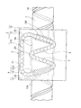
- FIG. 1 is a side view of the screw device
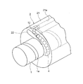
- FIG. 2 is a perspective view of the screw device
- FIG. 3 is a front view of the screw device viewed from the axial direction.
- the screw device includes a screw shaft 1, a nut 2 in which an opening 2a through which the screw shaft 1 passes is formed, and a plurality of balls 4 as rolling elements interposed between the screw shaft 1 and the nut 2 so as to be capable of rolling motion. .
- a ball rolling groove 1 a as a spiral rolling element rolling groove is formed on the outer peripheral surface of the screw shaft 1.
- the ball rolling groove 1a has a certain lead. In this embodiment, a single ball rolling groove 1a is shown, but the number of the ball rolling grooves 1a can be two or three.
- the cross-sectional shape of the ball rolling groove 1a is formed in a Gothic arch groove shape combining two arcs.
- the ball 4 contacts the ball rolling groove 1a of the screw shaft 1 at two points.
- the screw shaft 1 is made of steel.
- the surface of the ball rolling groove 1a is subjected to heat treatment and grinding using a grindstone so that the ball 4 rolls smoothly.
- a loaded ball rolling groove 2 b is formed as a spiral loaded rolling element rolling groove facing the ball rolling groove 1 a of the screw shaft 1.
- the number of leads and strips of the loaded ball rolling groove 2b is equal to the number of leads and strips of the ball rolling groove 1a.
- the cross-sectional shape of the load ball rolling groove 2b is also formed in a Gothic arch groove shape combining two arcs.
- the ball 4 contacts the load ball rolling groove 2b of the nut 2 at two points.
- the nut 2 (excluding circulating parts) is made of steel.
- the surface of the loaded ball rolling groove 2b is subjected to heat treatment and grinding using a grindstone so that the ball 4 rolls smoothly.
- a spiral loaded ball rolling path 3 is formed as a loaded rolling element rolling path.
- the clearance between the load ball rolling groove 2 b of the nut 2 and the ball rolling groove 1 a of the screw shaft 1 is smaller than the diameter of the ball 4, and the ball 4 is formed between the nut 2 and the screw shaft 1 in the load ball rolling path 3. Receiving compression load between.
- a return path 5 that connects one end and the other end of the spiral load ball rolling path 3 is formed.
- a plurality of balls 4 are arranged on the load ball rolling path 3 and the return path 5.
- a spacer (not shown) may be interposed between the balls 4.
- the ball 4 rolls while receiving a load between the ball rolling groove 1 a of the screw shaft 1 and the loaded ball rolling groove 2 b of the nut 2, and the center line of the ball 4 spirals. Become.
- the center line of the ball 4 deviates from the spiral.
- the inner diameter of the return path 5 (excluding the return path 5 immediately after exiting the loaded ball rolling path 3 as will be described later) is larger than the outer diameter of the ball 4, and the ball 4 can receive a load in the return path 5. Instead, it is pushed by the subsequent ball 4 to move.
- the ball 4 rolls along the loaded ball rolling path 3 while receiving a load.
- the ball 4 that has rolled to one end of the loaded ball rolling groove 2b of the nut 2 enters the return path 5 and is released from the load. After moving along the return path 5, the ball 4 returns to the other end of the loaded ball rolling groove 2b.
- the nut 2 includes a nut main body 21 in which the load ball rolling groove 2b is formed, and circulation parts 22 that are attached to both ends of the nut main body 21 in the axial direction.
- the nut body 21 is formed with a through hole 21a extending in the axial direction.
- a direction change path 12 is formed in the circulation component 22 attached to the nut body 21.
- the nut body 21 is formed with an outer peripheral side 13b of the curvature radius changing portion 13 by extending the load ball rolling groove 2b.
- the outer peripheral side 13b of the curvature radius changing portion 13 is shown by hatching for easy understanding (the outer peripheral side 13b of the curvature radius changing portion 13 is shown as a separate body from the nut main body 21; The outer peripheral side 13b of the portion 13 is integral with the nut body 21).
- the direction change path 12 of the circulation component 22 is connected to the through hole 21 a and the curvature radius changing portion 13.
- the through hole 21 a of the nut body 21, the direction changing path 12 of the circulating component 22, and the curvature radius changing portion 13 constitute the return path 5.
- the return path 5 is provided with a radius-of-curvature changing portion 13 continuously to the load ball rolling path 3.
- the track center line 3a of the ball 4 in the loaded ball rolling path 3 is indicated by a one-dot chain line, and the track center line 13a of the ball 4 in the curvature radius changing portion 13 is indicated by a bold line.
- the radius of curvature of the track center line 13 a of the ball 4 is equal to or greater than the radius of curvature of the track center line 3 a of the ball 4 in the loaded ball rolling path 3 and the distance from the loaded ball rolling path 3 increases ( In other words, the radius of curvature of the track center line 13a of the ball 4 increases gradually or stepwise as it approaches the direction change path 12.
- the track center line 13 a of the ball 4 is shifted outward from the track center line 3 a of the ball 4 in the loaded ball rolling path 3.
- the center of curvature of the track center line 13a of the ball 4 is located on the screw shaft 1 side.
- the tangential direction of the track center line 13a of the curvature radius changing portion 13 and the tangential direction of the track center line 3a of the load ball rolling path 3 coincide. That is, the track center line 13a of the curvature radius changing portion 13 is a curve having a lead. Moreover, in this connection location P1, the radius of curvature of the track center line 13a of the curvature radius changing portion 13 is equal to the radius of curvature of the track center line 3a of the load ball rolling path 3 or larger than the radius of curvature of the track center line 3a. As shown in FIG.
- the direction changing path 12 of the circulating component 22 as viewed from the axial direction of the nut 2 is formed linearly.
- the radius of curvature of the track center line 13a of the radius-of-curvature changing portion 13 becomes infinite at the connection point P2 between the circulation component 22 and the direction change path 12.
- the length of the radius-of-curvature changing portion 13 (the length of the track center line 13a from P1 to P2) is at least twice the ball diameter.
- P1 exists on a horizontal line that crosses the center of the nut 2 in the height direction, but approaches the circulating component 22 according to the trajectory of the trajectory centerline 13a of the curvature radius changing portion 13. It can also be separated from the circulating component 22.
- the ball 4 moves along the outer peripheral side 13 b of the curvature radius changing portion 13 formed on the nut 2.
- the track center line 13 a of the ball 4 in the curvature radius changing portion 13 coincides with the locus of the center of the ball 4 moving along the outer peripheral side 13 b of the curvature radius changing portion 13 of the nut 2.
- the ball 4 moves while being sandwiched between the loaded ball rolling groove 2 b of the nut 2 and the ball rolling groove 1 a of the screw shaft 1.
- the track center line 3a of the ball 4 coincides with the center line of the loaded ball rolling path 3 and is circular.
- the radius of curvature of the track center line 3a of the ball 4 in the loaded ball rolling path 3 is 1 ⁇ 2 of BCD (Ball CircleCDiameter).
- the orbit center line 13a of the ball 4 is a relaxation curve or a composite curve in which a plurality of arcs having different radii of curvature are combined.
- the relaxation curve is a curve used on an expressway or the like, and is a curve whose curvature continuously changes in proportion to the curve length. The relaxation curve will be described later.
- the compound curve is a curve obtained by combining two or more arcs such as radius R1 and radius R2 (which has a relation of R1 ⁇ R2).
- the outer peripheral side 13 b of the curvature radius changing portion 13 is formed on the nut 2.
- a portion 13C2 close to the load ball rolling path 3 on the inner peripheral side 13C of the curvature radius changing portion 13 is formed by the outer peripheral surface of the screw shaft 1, and a portion 13C1 away from the load ball rolling path 3 is formed in the circulating component 22.
- the outer peripheral side 13b of the curvature radius changing portion 13 is continuous with the load ball rolling groove 2b of the nut 2, and the ball 4 immediately after entering the outer peripheral side 13b of the curvature radius changing portion 13 from the load ball rolling groove 2b is also present.
- the load acts in the same manner as the ball 4 in the loaded ball rolling groove 2b.
- the ball 4 moving on the outer peripheral side 13b of the curvature radius changing portion 13 is gradually released from the load as it moves away from the loaded ball rolling groove 2b.
- the ball is completely released from the load in the middle of the curvature radius changing portion 13 (in the present embodiment, in the middle of the portion 13C2 close to the loaded ball rolling path 3) and enters the circulation component 22 in an unloaded state.
- FIG. 4A shows a perspective view of the nut body 21 viewed from the same direction as FIG. 2, and FIG. 4B shows a perspective view of the nut body 21 viewed from the opposite direction to FIG.
- a recess 31 in which the circulating component 22 is mounted is formed on the end surface of the nut body 21 in the axial direction.
- the recess 31 is connected to the through hole 21a.
- the direction changing path 12 of the circulating component 22 is connected to the through hole 21a.
- the outer peripheral side 13 b of the curvature radius changing portion 13 is formed by extending the load ball rolling groove 2 b.
- the cross-sectional shape of the outer peripheral side 13b of the curvature radius changing portion 13 is formed into a Gothic arch groove shape combining two arcs.
- the ball 4 contacts the outer peripheral side 13b of the curvature radius changing portion 13 of the nut 2 at two points.
- the concave portion 31 is also connected to the outer peripheral side 13 b of the curvature radius changing portion 13, and when the circulating component 22 is attached to the concave portion 31, the direction changing path 12 of the circulating component 22 is connected to the outer peripheral side 13 b of the curvature radius changing portion 13.
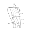
- FIG. 5 shows a perspective view of the circulation component 22.
- the circulating component 22 includes a main body portion 32 that is fitted in the concave portion 31 of the nut main body 21, and an extension portion 33 that is in contact with the inner peripheral surface of the nut 2.
- a direction changing path 12 is formed in the main body portion 32.
- the cross-sectional shape of the direction change path 12 is a circle having a radius larger than the radius of the ball 4.
- the extension portion 33 is formed thin by removing the lower portion of the main body portion 32.
- the extension portion 33 is formed with an inner peripheral side 13 c 1 of the curvature radius changing portion 13.
- the cross-sectional shape of the inner peripheral side 13 c 1 of the curvature radius changing portion 13 is a semicircle having a radius larger than the radius of the ball 4.
- the extension portion 33 constitutes the curvature radius changing portion 13 having a closed cross section in cooperation with the outer peripheral side 13b of the curvature radius changing portion 13 of the nut 2.
- a scooping portion 34 that scoops up the ball 4 is formed at the tip of the extension portion 33.
- the ball 4 is held in the circulating component 22 by the scooping portion 34.
- the outer peripheral side 13b of the curvature radius changing portion 13 of the nut 2 extends beyond the scooping portion 34 of the circulating component 22 (see FIG. 3).
- FIG. 6 is an explanatory diagram showing a relaxation curve (clothoid curve).
- the relaxation curve from the start point P 0 to the end point P 1 can be expressed by the following four parameters.
- h Length of the curve from the start point P 0 to the end point P 1 ⁇ 0 : Tangent angle at the start point P 0 ⁇ v : Increment of arc of tangent angle ⁇ u : Increment of clothoid of tangent angle
- the unit of the three angles is radian in the following formula.
- the point P on the relaxation curve can be obtained by Equation 1 using the dimensionless displacement S as a variable when the y-axis is the imaginary axis (j-axis).
- ⁇ is the tangential direction of the curve at point P
- S is the value obtained by dividing the length s of the curve from start point P 0 to point P by h.
- Curvature c v of the curve is determined by the number 2.
- the reduction ratio that is, the curvature change rate c u is obtained by Equation 3.
- the curvature change rate c u is a constant value. That is, the relaxation curve is a curve in which the curvature changes linearly (in a linear expression) with respect to the length of the curve, and by using this, a smooth curve in which the curvature changes continuously can be obtained.
- the manufacturing method of the outer peripheral side 13b of the curvature radius changing portion 13 is as follows.
- the loaded ball rolling groove 2b of the nut 2 is ground by applying a small-diameter grindstone to the loaded ball rolling groove 2b of the nut 2 and rotating the grindstone.
- the grinding wheel is moved in the axial direction of the nut 2 while rotating the nut 2.
- the spiral load ball rolling groove 2b can be ground. If the grindstone is further moved in the radial direction of the nut 2 along the relaxation curve after grinding the load ball rolling groove 2b of the nut 2, the outer peripheral side 13b of the curvature radius changing portion 13 can be ground.
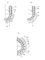
- FIG. 7 shows a comparison of the centrifugal force Pc acting on the ball 4 between the conventional tangential direction wrinkle and the curvature radius change wrinkle of the present embodiment.
- 7 (a) and 7 (b) show a conventional tangential scoop
- FIG. 7 (c) shows a curvature radius scoop of the present embodiment.
- FIG. 7A in the case of conventional tangential scooping, the track center line 3a of the ball 4 in the loaded ball rolling path 3 is a spiral, and the track center line 41a of the ball 4 in the return path 41 is a straight line. Become.
- the ball 4 travels in a spiral tangential direction from the loaded ball rolling path 3 to the return path 41.
- a constant centrifugal force Pc acts on the ball 4 moving on the loaded ball rolling path 3.
- the centrifugal force does not act on the ball 4 moving on the return path 41. For this reason, the centrifugal force acting on the ball 4 moving from the load ball rolling path 3 to the return path 41 or the ball 4 moving from the return path 41 to the load ball rolling path 3 changes abruptly.
- the ball 4 moves along the spiral trajectory in a state where the position is determined, whereas when entering the return path 41, it is larger than the ball diameter. Since the ball 4 moves in the cylinder, the ball 4 can freely move and move in the return path 41. For this reason, there is a shift in the center of the ball 4 between the state where it hits the cylindrical wall of the return path 41 and the position determined by the loaded ball rolling path 3, and there is a sudden change in the position of the ball 4 at the boundary 42. Arise. When the ball 4 is clogged, the track center line 41a of the ball 4 in the return path 41 becomes zigzag and the track center line 41a is not continuous.
- the radius of curvature of the track center line 13a of the radius-of-curvature changing portion 13 gradually changes, so that the acting centrifugal force The ball 4 enters the load ball rolling path 3 from the return path 5 while increasing, and the centrifugal force acting decreases from the load ball rolling path 3 to the return path 5. For this reason, it can suppress that the centrifugal force which acts on the ball
- the outer peripheral side 13b of the curvature radius changing portion 13 of the return path 5 is formed by extending the load ball rolling groove 2b of the nut 2, the ball is also formed at the boundary 43 between the load ball rolling path 3 and the return path 5.
- 4 orbit centerlines 3a and 13a are continuous, and the ball 4 smoothly moves on the boundary 43.
- the track center line 13a of the ball 4 is bent in the return path 5, a centrifugal force acts on the ball 4 moving on the return path 5. Since the balls 4 move along the return path 5 while being pressed against the outer peripheral side 13b of the return path 5 by the centrifugal force, the balls 4 are easily aligned in the return path 5. Even when the ball 4 is clogged, the force that presses the ball 4 against the outer peripheral side 13 b of the return path 5 works, and the balls 4 are easily aligned in the return path 5.
- FIG. 8 is a comparison of the rotation of the ball 4 between the conventional tangential direction and the curvature radius change according to the present embodiment.
- 8 (a) and 8 (b) show the conventional tangential direction scooping
- FIGS. 8 (c) and 8 (d) show the curvature radius scooping of this embodiment.
- FIG. 8A in the case of conventional tangential scooping, when the screw shaft 1 is rotated counterclockwise, the ball 4 moves along the spiral trajectory while rotating clockwise in the load ball rolling path 3. However, the ball 4 does not rotate in the cylindrical return path 41.
- FIG. 8 (b) when entering the loaded ball rolling path 3 from the return path 41, the ball 4 suddenly rotates from a state where it does not rotate, and the rotation state of the ball 4 changes abruptly. .
- the screw device according to the present embodiment further provides the following effects.
- the curvature radius changing portion 13 can be easily manufactured.
- the ball 4 can be rotated with the rotation of the screw shaft 1.
- the remaining portion 13C1 on the inner peripheral side of the curvature radius changing portion 13 is formed in the circulating component 22 to prevent excessive play around the ball 4 even if the curvature radius of the curvature radius changing portion 13 is increased. it can.
- the load ball rolling groove 2b of the nut body 21 and the cross-sectional shape of the outer peripheral side 13b of the curvature radius changing portion 13 into a Gothic arch groove shape that contacts the ball 4 at two points, the load ball rolling path 3 And the contact point of the ball before and after the boundary 43 of the return path 5 can be matched.
- the relaxation curve having a lead on the track center line of the radius of curvature change portion (that is, the tangential direction of the track center line of the radius of curvature change portion and the load at the connection point between the radius of curvature change portion and the load ball rolling path).
- the tangential direction of the track center line of the ball rolling path is perfectly matched), but if the load ball rolling path and the curvature radius change part can be smoothly connected, the track center line of the curvature radius change part has a lead.
- There may be no relaxation curve (for example, the orbital center line of the radius-of-curvature changing portion is arranged in a plane perpendicular to the axis of the nut).
- the outer peripheral side of the curvature radius changing portion is formed by extending the load ball rolling groove of the nut body
- the outer peripheral side of the curvature radius changing portion can also be formed in the circulating part.
- the nut circulation structure is an end deflector type (a system in which a circulation part in which a through hole is formed in the nut body and direction change paths 12 are formed at both ends in the axial direction of the nut body) is described.
- the nut circulation structure may be a return pipe type (a system in which a return pipe having a return path formed in the nut body is mounted).
- the cross-sectional shape of the load ball rolling groove of the nut main body and the cross-sectional shape of the outer peripheral side of the curvature radius changing portion is formed into a Gothic arch groove shape composed of two arcs.
- the shape can also be formed into a circular arc groove shape consisting of a single arc.
- rollers can be used as rolling elements.
Landscapes
- Engineering & Computer Science (AREA)
- General Engineering & Computer Science (AREA)
- Mechanical Engineering (AREA)
- Transmission Devices (AREA)
Abstract
Cette invention concerne un dispositif à vis conçu de façon à empêcher un brusque changement d'une force agissant sur des corps roulants ou un brusque changement de la position des corps roulants à la frontière entre le trajet de roulement hélicoïdal des corps roulants et le trajet de retour du dispositif à vis, de manière à assurer un déplacement régulier des corps roulants. Une section de changement de rayon de courbure (13) est disposée dans le trajet de retour (5) d'un dispositif à vis. Vue dans le sens axial d'un écrou (2), la section de changement de rayon de courbure de la ligne centrale du trajet (13a) des corps roulants (4) dans le trajet de retour (5) est supérieure ou égale au rayon de courbure de la ligne centrale du trajet (3a) des corps roulants dans un trajet de roulement chargé des corps roulants (3), et le rayon de courbure de la ligne centrale de trajet (13a) des corps roulants (4) dans le trajet de retour (5) va croissant de manière progressive ou par incréments à mesure que la distance de la section de changement de rayon de courbure au trajet de roulement chargé des corps roulants (3) augmente.
Priority Applications (3)
| Application Number | Priority Date | Filing Date | Title |
|---|---|---|---|
| US14/890,657 US9568078B2 (en) | 2013-05-31 | 2014-05-20 | Screw device |
| DE112014002636.0T DE112014002636T5 (de) | 2013-05-31 | 2014-05-20 | Gewindevorrichtung |
| CN201480030731.9A CN105247245B (zh) | 2013-05-31 | 2014-05-20 | 丝杠装置 |
Applications Claiming Priority (2)
| Application Number | Priority Date | Filing Date | Title |
|---|---|---|---|
| JP2013-114802 | 2013-05-31 | ||
| JP2013114802A JP6244108B2 (ja) | 2013-05-31 | 2013-05-31 | ねじ装置 |
Publications (1)
| Publication Number | Publication Date |
|---|---|
| WO2014192595A1 true WO2014192595A1 (fr) | 2014-12-04 |
Family
ID=51988628
Family Applications (1)
| Application Number | Title | Priority Date | Filing Date |
|---|---|---|---|
| PCT/JP2014/063365 Ceased WO2014192595A1 (fr) | 2013-05-31 | 2014-05-20 | Dispositif à vis |
Country Status (6)
| Country | Link |
|---|---|
| US (1) | US9568078B2 (fr) |
| JP (1) | JP6244108B2 (fr) |
| CN (2) | CN107630996B (fr) |
| DE (1) | DE112014002636T5 (fr) |
| TW (1) | TWI615566B (fr) |
| WO (1) | WO2014192595A1 (fr) |
Cited By (2)
| Publication number | Priority date | Publication date | Assignee | Title |
|---|---|---|---|---|
| WO2016114022A1 (fr) * | 2015-01-16 | 2016-07-21 | 日立オートモティブシステムズ株式会社 | Dispositif de direction assistée |
| US10371239B2 (en) | 2015-01-16 | 2019-08-06 | Hitachi Automotive Systems, Ltd. | Power steering device |
Families Citing this family (6)
| Publication number | Priority date | Publication date | Assignee | Title |
|---|---|---|---|---|
| JP2015161315A (ja) * | 2014-02-26 | 2015-09-07 | 株式会社ショーワ | ボールねじおよび操舵装置 |
| DE102015214859B4 (de) * | 2015-08-04 | 2017-12-14 | Schaeffler Technologies AG & Co. KG | Kugelgewindetrieb |
| JP6381703B2 (ja) | 2017-02-23 | 2018-08-29 | Thk株式会社 | ねじ装置 |
| JP6559817B1 (ja) * | 2018-02-08 | 2019-08-14 | Thk株式会社 | 転動体ねじ装置 |
| CN113767234B (zh) * | 2020-04-02 | 2023-11-14 | 日本精工株式会社 | 滚珠丝杠装置 |
| JP7877815B2 (ja) * | 2022-05-13 | 2026-06-23 | 日本精工株式会社 | ボールねじ装置 |
Citations (4)
| Publication number | Priority date | Publication date | Assignee | Title |
|---|---|---|---|---|
| JPS506963A (fr) * | 1973-05-26 | 1975-01-24 | ||
| JP2001141019A (ja) * | 1999-09-03 | 2001-05-25 | Nsk Ltd | ボールねじ装置 |
| JP2010025129A (ja) * | 2008-07-15 | 2010-02-04 | Thk Co Ltd | ボールねじ |
| JP2010025301A (ja) * | 2008-07-24 | 2010-02-04 | Jtekt Corp | ボールねじ |
Family Cites Families (15)
| Publication number | Priority date | Publication date | Assignee | Title |
|---|---|---|---|---|
| DE10042610B4 (de) * | 1999-09-03 | 2005-01-13 | Nsk Ltd. | "Kugelumlaufspindelvorrichtung" |
| US6675669B2 (en) * | 2000-08-23 | 2004-01-13 | Nsk Ltd. | Ball screw apparatus |
| JP2002181155A (ja) * | 2000-12-14 | 2002-06-26 | Nsk Ltd | ボールねじ |
| JP2003074663A (ja) * | 2001-09-05 | 2003-03-12 | Nsk Ltd | ボールねじ |
| JP2004019905A (ja) * | 2002-06-20 | 2004-01-22 | Nsk Ltd | 直動装置 |
| DE102004023353A1 (de) * | 2004-05-12 | 2005-12-08 | Ina-Schaeffler Kg | Kugelgewindetrieb |
| JP2006046530A (ja) * | 2004-08-05 | 2006-02-16 | Nsk Ltd | ボールねじ装置 |
| JP5252279B2 (ja) * | 2008-08-21 | 2013-07-31 | Smc株式会社 | ボールねじ機構 |
| CN101676576B (zh) * | 2008-09-16 | 2012-03-07 | 上银科技股份有限公司 | 滚珠螺杆模块及其使用的循环装置 |
| US20100139433A1 (en) * | 2008-12-07 | 2010-06-10 | Yan-Yu Chen | Ball screw with a circulation member |
| US20110303036A1 (en) * | 2009-01-06 | 2011-12-15 | Hiwin Technologies Corp. | Ball return device for ball screw device |
| JP2012112432A (ja) | 2010-11-24 | 2012-06-14 | Nsk Ltd | リターンチューブ及びその製造方法、並びにボールねじ |
| DE202011000240U1 (de) * | 2011-02-01 | 2011-06-01 | Hiwin Technologies Corp. | Kugelumlaufspindel mit einem Rücklaufelement |
| FR2980254B1 (fr) * | 2011-09-21 | 2014-05-23 | Skf Ab | Systeme de vis a billes muni d'un moyen de retenue d'un element de deviation des billes |
| DE102012213856B4 (de) * | 2012-05-10 | 2019-08-08 | Schaeffler Technologies AG & Co. KG | Spindelmutter für einen Kugelgewindetrieb und Elektromechanischer Bremskraftverstärker |
-
2013
- 2013-05-31 JP JP2013114802A patent/JP6244108B2/ja active Active
-
2014
- 2014-05-20 DE DE112014002636.0T patent/DE112014002636T5/de active Pending
- 2014-05-20 CN CN201711111226.9A patent/CN107630996B/zh active Active
- 2014-05-20 WO PCT/JP2014/063365 patent/WO2014192595A1/fr not_active Ceased
- 2014-05-20 US US14/890,657 patent/US9568078B2/en active Active
- 2014-05-20 CN CN201480030731.9A patent/CN105247245B/zh active Active
- 2014-05-29 TW TW103118761A patent/TWI615566B/zh active
Patent Citations (4)
| Publication number | Priority date | Publication date | Assignee | Title |
|---|---|---|---|---|
| JPS506963A (fr) * | 1973-05-26 | 1975-01-24 | ||
| JP2001141019A (ja) * | 1999-09-03 | 2001-05-25 | Nsk Ltd | ボールねじ装置 |
| JP2010025129A (ja) * | 2008-07-15 | 2010-02-04 | Thk Co Ltd | ボールねじ |
| JP2010025301A (ja) * | 2008-07-24 | 2010-02-04 | Jtekt Corp | ボールねじ |
Cited By (4)
| Publication number | Priority date | Publication date | Assignee | Title |
|---|---|---|---|---|
| WO2016114022A1 (fr) * | 2015-01-16 | 2016-07-21 | 日立オートモティブシステムズ株式会社 | Dispositif de direction assistée |
| JPWO2016114022A1 (ja) * | 2015-01-16 | 2017-08-24 | 日立オートモティブシステムズ株式会社 | パワーステアリング装置 |
| US10309502B2 (en) | 2015-01-16 | 2019-06-04 | Hitachi Automotive Systems, Ltd. | Power steering device |
| US10371239B2 (en) | 2015-01-16 | 2019-08-06 | Hitachi Automotive Systems, Ltd. | Power steering device |
Also Published As
| Publication number | Publication date |
|---|---|
| TWI615566B (zh) | 2018-02-21 |
| DE112014002636T5 (de) | 2016-03-03 |
| CN105247245A (zh) | 2016-01-13 |
| TW201508194A (zh) | 2015-03-01 |
| US9568078B2 (en) | 2017-02-14 |
| CN105247245B (zh) | 2017-12-12 |
| JP6244108B2 (ja) | 2017-12-06 |
| US20160091066A1 (en) | 2016-03-31 |
| CN107630996A (zh) | 2018-01-26 |
| CN107630996B (zh) | 2020-10-09 |
| JP2014234834A (ja) | 2014-12-15 |
Similar Documents
| Publication | Publication Date | Title |
|---|---|---|
| JP6244108B2 (ja) | ねじ装置 | |
| JP5255503B2 (ja) | 転動体ねじ装置 | |
| JP5132547B2 (ja) | ボールねじ装置 | |
| WO2007046321A1 (fr) | Dispositif a vis a billes | |
| JP2005299754A (ja) | ねじ装置及びその製造方法 | |
| CN101874167B (zh) | 滚柱丝杠及滚柱丝杠中滚柱的循环方法 | |
| WO2012081143A1 (fr) | Dispositif de vis à billes | |
| JP6559199B2 (ja) | ねじ装置 | |
| JP6187109B2 (ja) | ボールねじ | |
| JP5004312B2 (ja) | 駒式ボールねじ | |
| WO2007126025A1 (fr) | Vis a rouleau et procede de conception de passage de retour de rouleau non charge pour vis a rouleau | |
| WO2015045983A1 (fr) | Roue de meulage destinée à meuler une gorge hélicoïdale d'un arbre à vis pour une vis à billes et procédé de formation d'une gorge hélicoïdale | |
| JP2004068882A (ja) | ころねじ装置 | |
| CN101203698A (zh) | 滚柱螺杆及其制造方法 | |
| CN100529472C (zh) | 滚柱丝杠 | |
| JP2008157374A (ja) | ボールねじ機構 | |
| JP2004138214A (ja) | ボールねじ装置および該装置の製造方法 | |
| JP2003239967A (ja) | 直動装置 | |
| JP2005256937A (ja) | ボールねじ | |
| JP6221482B2 (ja) | ボール螺子装置及びこれを備えた電動パワーステアリング装置 | |
| JP2004068866A (ja) | ボールねじ装置 | |
| WO2025022524A1 (fr) | Dispositif de vis à billes | |
| JP2003247620A (ja) | ローラーねじ機構 | |
| JP2006242252A (ja) | ボールねじ機構 | |
| JP2006336690A (ja) | 直動装置 |
Legal Events
| Date | Code | Title | Description |
|---|---|---|---|
| 121 | Ep: the epo has been informed by wipo that ep was designated in this application |
Ref document number: 14803823 Country of ref document: EP Kind code of ref document: A1 |
|
| WWE | Wipo information: entry into national phase |
Ref document number: 14890657 Country of ref document: US |
|
| WWE | Wipo information: entry into national phase |
Ref document number: 112014002636 Country of ref document: DE |
|
| 122 | Ep: pct application non-entry in european phase |
Ref document number: 14803823 Country of ref document: EP Kind code of ref document: A1 |