WO2014193103A1 - Robot de nettoyage de conduit - Google Patents
Robot de nettoyage de conduit Download PDFInfo
- Publication number
- WO2014193103A1 WO2014193103A1 PCT/KR2014/004302 KR2014004302W WO2014193103A1 WO 2014193103 A1 WO2014193103 A1 WO 2014193103A1 KR 2014004302 W KR2014004302 W KR 2014004302W WO 2014193103 A1 WO2014193103 A1 WO 2014193103A1
- Authority
- WO
- WIPO (PCT)
- Prior art keywords
- air
- robot
- pipe
- dust
- electric motor
- Prior art date
- Legal status (The legal status is an assumption and is not a legal conclusion. Google has not performed a legal analysis and makes no representation as to the accuracy of the status listed.)
- Ceased
Links
Images




Classifications
-
- B—PERFORMING OPERATIONS; TRANSPORTING
- B08—CLEANING
- B08B—CLEANING IN GENERAL; PREVENTION OF FOULING IN GENERAL
- B08B9/00—Cleaning hollow articles by methods or apparatus specially adapted thereto
- B08B9/02—Cleaning pipes or tubes or systems of pipes or tubes
- B08B9/027—Cleaning the internal surfaces; Removal of blockages
- B08B9/032—Cleaning the internal surfaces; Removal of blockages by the mechanical action of a moving fluid, e.g. by flushing
-
- B—PERFORMING OPERATIONS; TRANSPORTING
- B08—CLEANING
- B08B—CLEANING IN GENERAL; PREVENTION OF FOULING IN GENERAL
- B08B9/00—Cleaning hollow articles by methods or apparatus specially adapted thereto
- B08B9/02—Cleaning pipes or tubes or systems of pipes or tubes
- B08B9/027—Cleaning the internal surfaces; Removal of blockages
- B08B9/04—Cleaning the internal surfaces; Removal of blockages using cleaning devices introduced into and moved along the pipes
- B08B9/049—Cleaning the internal surfaces; Removal of blockages using cleaning devices introduced into and moved along the pipes having self-contained propelling means for moving the cleaning devices along the pipes, i.e. self-propelled
-
- F—MECHANICAL ENGINEERING; LIGHTING; HEATING; WEAPONS; BLASTING
- F24—HEATING; RANGES; VENTILATING
- F24F—AIR-CONDITIONING; AIR-HUMIDIFICATION; VENTILATION; USE OF AIR CURRENTS FOR SCREENING
- F24F13/00—Details common to, or for air-conditioning, air-humidification, ventilation or use of air currents for screening
- F24F13/02—Ducting arrangements
-
- F—MECHANICAL ENGINEERING; LIGHTING; HEATING; WEAPONS; BLASTING
- F24—HEATING; RANGES; VENTILATING
- F24F—AIR-CONDITIONING; AIR-HUMIDIFICATION; VENTILATION; USE OF AIR CURRENTS FOR SCREENING
- F24F2221/00—Details or features not otherwise provided for
- F24F2221/22—Cleaning ducts or apparatus
Definitions
- the present invention relates to a robot for cleaning a duct, and in more detail, in order to be able to suck and remove dust generated while easily cleaning various foreign substances including the dust accumulated inside the duct on the inner wall surface.
- the developed duct cleaning robot is a robot for cleaning a duct, and in more detail, in order to be able to suck and remove dust generated while easily cleaning various foreign substances including the dust accumulated inside the duct on the inner wall surface.
- ducts are for ventilation and blowing. As air enters and exits, various foreign matters contained in the air gradually accumulate in the ducts, and this becomes a proper requirement for various molds or bacteria to grow over time.
- harmful elements such as dust or foreign matter accumulated in the duct can be introduced into the room through the duct during ventilation or air purification, which can cause diseases of the bronchial system, causing harmful effects on the human body and polluting indoor air. It is the cause.
- the ducts installed on the ceiling of buildings or subways supply cool air during the summer season to cool and air-condition the platform.
- the wind is supplied during the summer, the cold air is supplied to air the platform again.
- the accumulated dust is ejected to the platform with cold air, causing discomfort to people or diseases of the circulatory system.
- the present invention has been developed in order to solve the above problems, the object is to develop a duct cleaning robot that can effectively collect the dust collected when the dust accumulated by the compressed air in the air.
- the present invention provides a duct cleaning robot for cleaning the inside by injecting a high-pressure air to the inside of the duct through a robot controlled electric vehicle equipped with a wheel;
- a robot electric vehicle having four or more wheels driven by an internal motor and having a camera mounted at the front and the rear;
- a control unit having a compressor and having a controller for controlling the robot train and an electric wire and an air pipe for controlling the robot train;
- Two or more bellows-type suction pipes extending from the front to the front of the robot train, a manifold for collecting the air sucked from the rear of the two or more suction pipes into a space, and mounted at the rear of the robot train.
- a dust collecting unit having a filter therein, a connecting pipe connecting the manifold and the dust collecting unit, and several air spray nozzles for injecting air inclined toward the rear dust collecting unit in the middle of the connecting pipe; ;
- Two or more air injection pipes extending from the front of the robot electric vehicle in the front direction, an air pipe mounting portion to which the end of the air pipe is mounted from the rear of the robot electric vehicle, and the air supplied by branching the air into two or more Air supply pipe line for supplying and supplying to the injection pipe, an air discharge pipe line branched from the air supply pipe line and connected to the several air spray nozzles, and an adjustment screw mounting hole having a thread formed on the inner circumferential surface through the air discharge pipe line from the rear side.
- an injection device configured to be mounted to the adjustment screw mounting hole and configured to include an adjustment screw that adjusts the air entering and exiting the air discharge pipe.
- a long flow pipe-type air spray pipe which is mounted at the end of the air injection pipe and branched in two directions, is composed of a flexible material that is bent well and is mounted at one end of the branch of the injection connector. It is characterized in that the mounting.
- the injector is characterized in that it further comprises a motor for rotating the adjustment screw.
- the present invention sprays high-pressure air to blow out dust and foreign matter accumulated in the duct into the air and sucks it again to filter out only dust and foreign matter by the dust collector to increase the cleaning efficiency of the duct and separately inside the duct. There is no need to vent the foreign matter by blowing air to the outside.
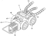
- Figure 2 is a front perspective view showing a robot electric vehicle according to an embodiment of the present invention
- FIG. 3 is a rear perspective view showing a robot electric vehicle according to an embodiment of the present invention.
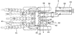
- FIG. 4 is a conceptual diagram showing the structure of the dust collector and injector according to an embodiment of the present invention
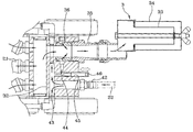
- FIG. 5 is a partially enlarged view showing the structure of a dust collecting device and an injection device according to an embodiment of the present invention
- FIG. 6 is a front perspective view showing a robot electric vehicle according to another embodiment of the present invention.
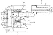
- Figure 8 is a partially enlarged view showing the structure of the dust collector and injector according to another embodiment of the present invention.
- FIG. 1 is a state diagram used according to an embodiment of the present invention
- Figure 2 is a front perspective view showing a robot electric vehicle according to an embodiment of the present invention
- Figure 3 is a rear view showing a robot electric vehicle according to an embodiment of the present invention
- 4 is a conceptual view showing the structure of the dust collector and the injector according to an embodiment of the present invention
- Figure 5 is a partial enlarged view showing the structure of the dust collector and the injector according to an embodiment of the present invention.
- the duct cleaning robot having a wheel (11) and to clean the inside by spraying a high-pressure air into the inside of the duct (10) through the robot controlled electric vehicle (1) wired;
- a robot electric vehicle 1 having four or more wheels 11 driven by an internal motor and having cameras 12 and 13 mounted on the front and the rear;
- a control unit (2) having a compressor and having a controller (21) for controlling the robot train (1) and an electric wire and an air pipe (22) for controlling the robot train (1);
- Two or more bellows-type suction pipes 31 extending in the front direction from the front of the robot electric vehicle 1 and a manifold for collecting the air sucked from the rear of the two or more suction pipes 31 into one space.
- a dust collecting part (34) mounted at the rear of the robot train (1) and having a filter (33) therein, and a connecting pipe (35) connecting the manifold (32) and the dust collecting part (34).
- a dust collector (3) composed of several air spray nozzles (36) for injecting air inclined toward the rear dust collector in the middle of the connecting pipe (35);
- the duct cleaning robot is characterized in that it comprises an injection device (4) consisting of a control screw 46 for adjusting the air entering and exiting the air discharge line (44).
- the first feature of the present application is that a dust collecting device 3 capable of separately collecting dust is provided, and a means for driving the dust collecting device 3 is supplied with an air supplied by using the spare air in the injector 4. This can be said to be able to spray and collect at the same time.
- the air discharged from the air discharge pipe path 44 is connected to a passage that surrounds the connecting fan 35 in a ring shape, and when the plurality of air spray nozzles 36 inject air to the rear, the suction pipe ( 31) air containing dust and foreign substances is sucked through.
- the cross section through which the air of the air discharge line 44 passes is changed according to the degree to which the adjustment screw 46 is inserted, and as a result, the amount of discharge can be adjusted.
- the cameras 12 and 13 are used to check the state of cleaning. When the dust is too much and the front camera 12 cannot check, the rear camera 13 can check the cleaning state. If the condition is not good, reverse and clean again.
- FIG. 6 is a front perspective view showing a robot electric vehicle according to another embodiment of the present invention
- Figure 7 is a state diagram according to another embodiment of the present invention
- the air injection pipe 41 is mounted on the end of the air in two directions
- a branched injection connector 47 and a long tubular flow-type air injection pipe 48 made of a flexible material that is well bent and mounted at one end of the injection connector 47 are additionally mounted.
- An example is given.
- the inside of the duct 10 is particularly a lot of dust and foreign matter is accumulated on the bottom surface can be buried in the side wall and ceiling, in particular more dust and foreign matter is present in the corner.
- the air injection pipe 41 in order to remove the dust and foreign matter in this portion, it is preferable to direct the air injection pipe 41 in a variety of directions, but the high-pressure air is regularly sprayed in one direction is not effective to shake off the accumulated dust.
- the flow-type air spray pipe 46 is formed, which is made of a material such as cloth, and when the air is sprayed, it has a property of immediately preceding it, but when it is attached to the resistance, the direction is sharply turned to face the other direction and the resistance. If you do this, the direction will be reversed again.
- FIG. 8 is a partially enlarged view showing the structure of the dust collector and the injector according to another embodiment of the present invention, wherein the injector 4 is further provided with a motor 49 for rotating the adjusting screw 46.
- An embodiment is characterized by the above.
- the above embodiment is a proposed embodiment for determining whether to increase the air injection amount or the intake amount while monitoring the internal situation through a camera, and to control and adjust the motor 49 remotely.
- suction pipe 32 manifold
Landscapes
- Engineering & Computer Science (AREA)
- Mechanical Engineering (AREA)
- Cleaning In General (AREA)
- Nozzles (AREA)
Abstract
La présente invention porte sur un robot de nettoyage de conduit développé pour nettoyer facilement divers types de substances étrangères, notamment la poussière accumulée à l'intérieur d'un conduit, avant que les substances étrangères durcissent sur la surface de paroi interne et aspirer et enlever la poussière produite. Le robot de nettoyage de conduit projette de l'air à haute pression à l'intérieur d'un conduit et nettoie l'intérieur à l'aide d'un charriot à moteur électrique de robot doté de roues et commandé avec fil. Le robot de nettoyage de conduit comprend : un chariot à moteur électrique de robot ayant au moins quatre roues, qui sont entraînées par un moteur interne, et des caméras montées sur les côtés avant et arrière, respectivement ; une unité de commande ayant un dispositif de commande, qui a un compresseur et qui commande le chariot à moteur électrique de robot et un fil et un conduit d'air conçus pour commander le chariot à moteur électrique de robot ; un dispositif de dépoussiérage comprenant au moins deux conduits d'admission de type cymbale s'étendant à partir de l'avant du chariot à moteur électrique de robot vers l'avant, une rampe destinée à faire converger l'air, qui a été pris à partir de l'arrière des au moins deux conduits d'admission, dans un espace, une unité de dépoussiérage montée sur l'arrière du chariot à moteur électrique de robot et contenant un filtre, un conduit de raccordement pour le raccordement de la rampe et de l'unité de dépoussiérage et un certain nombre de buses de projection d'air servant à projeter de l'air de façon oblique, au milieu du conduit de raccordement, en direction de l'unité de dépoussiérage à l'arrière ; et un dispositif de projection comprenant au moins deux tubes de projection d'air s'étendant à partir de l'avant du chariot à moteur électrique de robot vers l'avant, une unité de montage de conduit d'air, sur laquelle une extrémité du conduit d'air est montée à l'arrière du chariot à moteur électrique de robot, une conduite d'apport d'air servant à diviser l'air apporté en au moins deux courants et à raccorder/apporter les courants aux conduits de projection d'air, une conduite d'évacuation d'air partant en dérivation de la conduite d'apport d'air destinée à être raccordée aux buses de projection d'air, un trou de montage de vis de réglage s'étendant à travers la conduite d'évacuation d'air à partir de l'arrière et ayant un filetage formé sur sa surface périphérique interne et une vis de réglage montée dans le trou de montage de vis de réglage de façon à ce qu'une extrémité de la vis de réglage règle l'air qui est introduit dans la conduite d'évacuation d'air/évacué de cette dernière.
Priority Applications (1)
| Application Number | Priority Date | Filing Date | Title |
|---|---|---|---|
| CN201480028972.XA CN105473242B (zh) | 2013-05-30 | 2014-05-14 | 管道清洁机器人 |
Applications Claiming Priority (2)
| Application Number | Priority Date | Filing Date | Title |
|---|---|---|---|
| KR10-2013-0061423 | 2013-05-30 | ||
| KR1020130061423A KR101338381B1 (ko) | 2013-05-30 | 2013-05-30 | 덕트 청소용 로봇 |
Publications (1)
| Publication Number | Publication Date |
|---|---|
| WO2014193103A1 true WO2014193103A1 (fr) | 2014-12-04 |
Family
ID=49987606
Family Applications (1)
| Application Number | Title | Priority Date | Filing Date |
|---|---|---|---|
| PCT/KR2014/004302 Ceased WO2014193103A1 (fr) | 2013-05-30 | 2014-05-14 | Robot de nettoyage de conduit |
Country Status (3)
| Country | Link |
|---|---|
| KR (1) | KR101338381B1 (fr) |
| CN (1) | CN105473242B (fr) |
| WO (1) | WO2014193103A1 (fr) |
Cited By (2)
| Publication number | Priority date | Publication date | Assignee | Title |
|---|---|---|---|---|
| US9518390B1 (en) * | 2016-01-05 | 2016-12-13 | Albert Chao | Self propelled blower |
| CN114440696A (zh) * | 2022-03-30 | 2022-05-06 | 湖南文理学院 | 一种基于紧凑式微通道换热器的空气清洁系统 |
Families Citing this family (8)
| Publication number | Priority date | Publication date | Assignee | Title |
|---|---|---|---|---|
| WO2016190494A1 (fr) * | 2015-05-22 | 2016-12-01 | 한국항공우주연구원 | Procédé et appareil d'élimination de substances étrangères |
| CN108421780B (zh) * | 2018-03-15 | 2020-09-18 | 苏州热工研究院有限公司 | 一种蒸汽发生器的清洗和视频检查装置及其使用方法 |
| CN109176450B (zh) * | 2018-10-12 | 2020-04-28 | 清华四川能源互联网研究院 | 主从机器人系统 |
| KR102017063B1 (ko) * | 2018-12-24 | 2019-09-02 | 주식회사 이지건축 | 공동주택용 전기배선 케이블 리더 |
| KR102188609B1 (ko) | 2018-12-28 | 2020-12-09 | (주)디엠비에이치 | 집진 청소용 로봇 |
| KR102153672B1 (ko) | 2020-05-19 | 2020-09-09 | 주식회사 더브라이트 | 덕트 청소용 로봇 제어 방법, 장치, 및 시스템 |
| KR102736460B1 (ko) * | 2023-04-10 | 2024-11-29 | (주)제이티피솔루션 | 배관 내 파우더 융해 및 흡입 작업이 동시에 가능한 배관 클리닝 장치 |
| CN117773974B (zh) * | 2024-02-23 | 2024-05-03 | 北京信莱能源技术有限公司 | 一种风电叶片内窥检测巡检机器人 |
Citations (4)
| Publication number | Priority date | Publication date | Assignee | Title |
|---|---|---|---|---|
| JPH0699154A (ja) * | 1992-09-22 | 1994-04-12 | Tokyo Koken Kk | 空調用ダクト清掃装置 |
| KR200328747Y1 (ko) * | 2003-07-02 | 2003-10-01 | 대우조선해양 주식회사 | 파이프 청소장치 |
| KR100676689B1 (ko) * | 2005-11-25 | 2007-02-01 | 차희천 | 덕트용 흡출식 청소로봇 |
| JP2009274037A (ja) * | 2008-05-16 | 2009-11-26 | Hiroaki Ito | 空調ダクト内の清掃装置 |
Family Cites Families (5)
| Publication number | Priority date | Publication date | Assignee | Title |
|---|---|---|---|---|
| JPH0315188Y2 (fr) * | 1985-08-21 | 1991-04-03 | ||
| JP2945862B2 (ja) * | 1995-12-15 | 1999-09-06 | アタカ工業株式会社 | ダクト内サンプリング装置 |
| JP2005163619A (ja) * | 2003-12-02 | 2005-06-23 | Smc Corp | 真空発生用ユニット |
| CN1907583A (zh) * | 2005-08-05 | 2007-02-07 | 金银龙 | 一种多功能管道清扫机器人 |
| CN201579232U (zh) * | 2009-11-17 | 2010-09-15 | 上海北大方正科技电脑系统有限公司 | 一种计算机设备清洁器 |
-
2013
- 2013-05-30 KR KR1020130061423A patent/KR101338381B1/ko active Active
-
2014
- 2014-05-14 WO PCT/KR2014/004302 patent/WO2014193103A1/fr not_active Ceased
- 2014-05-14 CN CN201480028972.XA patent/CN105473242B/zh active Active
Patent Citations (4)
| Publication number | Priority date | Publication date | Assignee | Title |
|---|---|---|---|---|
| JPH0699154A (ja) * | 1992-09-22 | 1994-04-12 | Tokyo Koken Kk | 空調用ダクト清掃装置 |
| KR200328747Y1 (ko) * | 2003-07-02 | 2003-10-01 | 대우조선해양 주식회사 | 파이프 청소장치 |
| KR100676689B1 (ko) * | 2005-11-25 | 2007-02-01 | 차희천 | 덕트용 흡출식 청소로봇 |
| JP2009274037A (ja) * | 2008-05-16 | 2009-11-26 | Hiroaki Ito | 空調ダクト内の清掃装置 |
Cited By (2)
| Publication number | Priority date | Publication date | Assignee | Title |
|---|---|---|---|---|
| US9518390B1 (en) * | 2016-01-05 | 2016-12-13 | Albert Chao | Self propelled blower |
| CN114440696A (zh) * | 2022-03-30 | 2022-05-06 | 湖南文理学院 | 一种基于紧凑式微通道换热器的空气清洁系统 |
Also Published As
| Publication number | Publication date |
|---|---|
| KR101338381B1 (ko) | 2013-12-06 |
| CN105473242B (zh) | 2017-06-09 |
| CN105473242A (zh) | 2016-04-06 |
Similar Documents
| Publication | Publication Date | Title |
|---|---|---|
| KR101338381B1 (ko) | 덕트 청소용 로봇 | |
| KR101530637B1 (ko) | 환기배관 청소장치 | |
| KR100810152B1 (ko) | 미세먼지 청소차 | |
| JP2015000387A (ja) | 空調ダクト内洗浄システム | |
| FR2858204B1 (fr) | Robot et systeme epurateur d'air | |
| JPH0810189A (ja) | 吸着式壁面洗浄装置 | |
| WO2013191465A1 (fr) | Robot de nettoyage ayant une fonction de stérilisation du sol | |
| BR0016691B1 (pt) | sistema de sucÇço respiratària. | |
| JP2017013025A (ja) | 空調ダクト内洗浄システム | |
| CN1060681C (zh) | 液体喷雾空气净化装置 | |
| JP4237466B2 (ja) | ダクト内洗浄システム | |
| KR20170103211A (ko) | 전열교환기에 적용되는 환기 덕트의 청소 장치 및 청소 방법 | |
| KR102210119B1 (ko) | 비산방지 기능을 가지는 건물외벽 무인 도장장치 | |
| CN107816003A (zh) | 清扫车 | |
| CN207954161U (zh) | 一种木工车间的除尘系统 | |
| CN216554000U (zh) | 一种供风除尘系统 | |
| WO2011031036A2 (fr) | Robot de nettoyage à retour d'air d'évacuation équipé d'un générateur d'anions désinfectants | |
| CN100366139C (zh) | 棉花收获机行装置的输送结构 | |
| CN212914958U (zh) | 一种建筑工程施工降尘装置 | |
| CN2900104Y (zh) | 中央空调风管清洗机器人 | |
| US20120260455A1 (en) | Reflux-type exhaust robot cleaning device | |
| CN214406336U (zh) | 一种化妆品车间用除尘换气装置 | |
| CN110940027A (zh) | 一种除尘加湿新风系统 | |
| CN2421529Y (zh) | 通风管清洁用的吸尘装置 | |
| CN106500208A (zh) | 杀菌装置以及空调系统 |
Legal Events
| Date | Code | Title | Description |
|---|---|---|---|
| WWE | Wipo information: entry into national phase |
Ref document number: 201480028972.X Country of ref document: CN |
|
| 121 | Ep: the epo has been informed by wipo that ep was designated in this application |
Ref document number: 14804903 Country of ref document: EP Kind code of ref document: A1 |
|
| NENP | Non-entry into the national phase |
Ref country code: DE |
|
| 122 | Ep: pct application non-entry in european phase |
Ref document number: 14804903 Country of ref document: EP Kind code of ref document: A1 |