WO2014196151A1 - 排水処理装置 - Google Patents
排水処理装置 Download PDFInfo
- Publication number
- WO2014196151A1 WO2014196151A1 PCT/JP2014/002760 JP2014002760W WO2014196151A1 WO 2014196151 A1 WO2014196151 A1 WO 2014196151A1 JP 2014002760 W JP2014002760 W JP 2014002760W WO 2014196151 A1 WO2014196151 A1 WO 2014196151A1
- Authority
- WO
- WIPO (PCT)
- Prior art keywords
- carrier
- waste water
- filtration membrane
- drainage
- filtration
- Prior art date
- Legal status (The legal status is an assumption and is not a legal conclusion. Google has not performed a legal analysis and makes no representation as to the accuracy of the status listed.)
- Ceased
Links
Images

Classifications
-
- B—PERFORMING OPERATIONS; TRANSPORTING
- B01—PHYSICAL OR CHEMICAL PROCESSES OR APPARATUS IN GENERAL
- B01D—SEPARATION
- B01D61/00—Processes of separation using semi-permeable membranes, e.g. dialysis, osmosis or ultrafiltration; Apparatus, accessories or auxiliary operations specially adapted therefor
- B01D61/14—Ultrafiltration; Microfiltration
- B01D61/18—Apparatus therefor
-
- B—PERFORMING OPERATIONS; TRANSPORTING
- B01—PHYSICAL OR CHEMICAL PROCESSES OR APPARATUS IN GENERAL
- B01D—SEPARATION
- B01D65/00—Accessories or auxiliary operations, in general, for separation processes or apparatus using semi-permeable membranes
- B01D65/08—Prevention of membrane fouling or of concentration polarisation
-
- C—CHEMISTRY; METALLURGY
- C02—TREATMENT OF WATER, WASTE WATER, SEWAGE, OR SLUDGE
- C02F—TREATMENT OF WATER, WASTE WATER, SEWAGE, OR SLUDGE
- C02F3/00—Biological treatment of water, waste water, or sewage
- C02F3/02—Aerobic processes
- C02F3/08—Aerobic processes using moving contact bodies
- C02F3/085—Fluidized beds
-
- C—CHEMISTRY; METALLURGY
- C02—TREATMENT OF WATER, WASTE WATER, SEWAGE, OR SLUDGE
- C02F—TREATMENT OF WATER, WASTE WATER, SEWAGE, OR SLUDGE
- C02F3/00—Biological treatment of water, waste water, or sewage
- C02F3/02—Aerobic processes
- C02F3/12—Activated sludge processes
- C02F3/1236—Particular type of activated sludge installations
- C02F3/1268—Membrane bioreactor systems
- C02F3/1273—Submerged membrane bioreactors
-
- B—PERFORMING OPERATIONS; TRANSPORTING
- B01—PHYSICAL OR CHEMICAL PROCESSES OR APPARATUS IN GENERAL
- B01D—SEPARATION
- B01D2315/00—Details relating to the membrane module operation
- B01D2315/06—Submerged-type; Immersion type
-
- B—PERFORMING OPERATIONS; TRANSPORTING
- B01—PHYSICAL OR CHEMICAL PROCESSES OR APPARATUS IN GENERAL
- B01D—SEPARATION
- B01D2321/00—Details relating to membrane cleaning, regeneration, sterilization or to the prevention of fouling
- B01D2321/18—Use of gases
- B01D2321/185—Aeration
-
- B—PERFORMING OPERATIONS; TRANSPORTING
- B01—PHYSICAL OR CHEMICAL PROCESSES OR APPARATUS IN GENERAL
- B01D—SEPARATION
- B01D65/00—Accessories or auxiliary operations, in general, for separation processes or apparatus using semi-permeable membranes
- B01D65/02—Membrane cleaning or sterilisation ; Membrane regeneration
- B01D65/04—Membrane cleaning or sterilisation ; Membrane regeneration with movable bodies, e.g. foam balls
-
- C—CHEMISTRY; METALLURGY
- C02—TREATMENT OF WATER, WASTE WATER, SEWAGE, OR SLUDGE
- C02F—TREATMENT OF WATER, WASTE WATER, SEWAGE, OR SLUDGE
- C02F3/00—Biological treatment of water, waste water, or sewage
- C02F2003/001—Biological treatment of water, waste water, or sewage using granular carriers or supports for the microorganisms
- C02F2003/003—Biological treatment of water, waste water, or sewage using granular carriers or supports for the microorganisms using activated carbon or the like
-
- C—CHEMISTRY; METALLURGY
- C02—TREATMENT OF WATER, WASTE WATER, SEWAGE, OR SLUDGE
- C02F—TREATMENT OF WATER, WASTE WATER, SEWAGE, OR SLUDGE
- C02F3/00—Biological treatment of water, waste water, or sewage
- C02F3/02—Aerobic processes
- C02F3/12—Activated sludge processes
- C02F3/20—Activated sludge processes using diffusers
- C02F3/201—Perforated, resilient plastic diffusers, e.g. membranes, sheets, foils, tubes, hoses
-
- Y—GENERAL TAGGING OF NEW TECHNOLOGICAL DEVELOPMENTS; GENERAL TAGGING OF CROSS-SECTIONAL TECHNOLOGIES SPANNING OVER SEVERAL SECTIONS OF THE IPC; TECHNICAL SUBJECTS COVERED BY FORMER USPC CROSS-REFERENCE ART COLLECTIONS [XRACs] AND DIGESTS
- Y02—TECHNOLOGIES OR APPLICATIONS FOR MITIGATION OR ADAPTATION AGAINST CLIMATE CHANGE
- Y02W—CLIMATE CHANGE MITIGATION TECHNOLOGIES RELATED TO WASTEWATER TREATMENT OR WASTE MANAGEMENT
- Y02W10/00—Technologies for wastewater treatment
- Y02W10/10—Biological treatment of water, waste water, or sewage
Definitions
- the present invention relates to a waste water treatment apparatus for treating organic waste water using activated sludge carried on a carrier.
- an apparatus of this type comprises an aeration tank for aeration of sewage to perform activated sludge treatment, and a filtration membrane apparatus provided in the aeration tank for solid-liquid separation of the activated sludge mixture in the tank by filtration. And a suction pump connected to the filtration membrane device for sucking the filtrate by the same member to flow out to the outside, and a suction pump provided in a suction path connecting the filtration membrane device and the suction pump And a pressure gauge for measuring suction negative pressure.
- Patent No. 3142792 JP 2000-197895 A Japanese Patent Laid-Open No. 2002-192184
- a resin filtration membrane made of a resin material such as polyolefin is adopted as the filtration membrane, and when the rigid one having a large specific gravity is adopted as the carrier, the carrier is a filtration membrane. There is a risk that the filter membrane may be destroyed by contacting with.
- the resin filter membrane may be broken by the impact of the support as described above. Further, the carrier may be caught between the filtration membranes, or the carrier may be in contact with the wall surface of the treatment tank to be crushed, and the treatment of the carrier in the crushed portion may be complicated.
- the present invention has been made in view of such problems, and an object of the present invention is to provide a waste water treatment apparatus whose treatment efficiency is improved by using a carrier.
- the waste water treatment apparatus of the present invention comprises a treatment tank in which waste water containing activated sludge is stored, a hard filtration membrane to be immersed in the waste water, and a gas for generating a gas under the hard filtration membrane inside the waste water.
- a hard carrier comprising a hard material having a specific gravity larger than that of water is added to the drainage contained in the treatment tank, and the activated sludge is carried on the hard carrier.
- a small-sized hard material having a specific gravity larger than that of water is employed as a material of a carrier that carries microorganisms contained in activated sludge. Therefore, the carrier is substantially uniformly dispersed in the drainage without the carrier floating on the upper surface of the drainage, and the treatment efficiency of the drainage is improved.
- the waste water treatment apparatus 10 of the present invention comprises a treatment tank 12 in which waste water 24 is stored, a filtration membrane 16 immersed in the waste water 24, and a diffuser 28 disposed below the treatment tank 12 to generate air 30. And a pump 18 that communicates with the filtration membrane 16 via a pipe to apply suction pressure.
- pipes connecting the respective elements are indicated by thick solid lines.
- the function of the waste water treatment apparatus 10 of this embodiment is to reduce the organic substances contained in the waste water 24 with the activated sludge contained in the treatment tank 12 and further to take out the filtered water 26 filtered by the filtration membrane 16 to the outside. There is. Therefore, the filtered water 26 after being treated by the waste water treatment apparatus 10 according to the present embodiment contains less organic matter as compared with the waste water 24 to be introduced, and further contains almost no organic solid matter. It is a state. Furthermore, in the present embodiment, the carrier is added to the waste water stored in the treatment tank 12, whereby the microorganisms contained in the activated sludge 32 are maintained at a high concentration, and the treatment efficiency is high.
- the waste water 24 to be treated in the present embodiment is one in which organic substances are contained in water at a high concentration, and specifically, general sewage including manure and the like, waste water discharged from a food factory and the like, and the like.
- the treatment tank 12 is a container made of metal or resin made of stainless steel or the like, and has a role of storing the drainage 24 to be filtered, the filtration membrane 16 and the like. Sludge treatment and filtration treatment of the drainage 24 are performed in the treatment tank 12.
- the filtration membrane 16 is a flat membrane filtration membrane here, and is immersed in the drainage 24 stored in the processing tank 12.
- the filtration membrane 16 is in a state in which the filtration surface that substantially performs filtration is entirely immersed in the drainage 24.
- the internal space of the filtration membrane 16 communicates with the pump 18 via a pipe, and the drainage 18 is filtered by the filtration membrane 16 by the pump 18 applying a predetermined suction pressure to the internal space of the filtration membrane 16 .
- filtered water which is the filtered waste water 24 is taken out of the processing tank 12.
- a resin material, ceramic, sintered metal, a metal plate provided with fine filtration holes, or the like is employed as a material of the filtration membrane 16. Although only one filtration membrane 16 is immersed in the drainage 24 in FIG. 1A, in practice, a plurality of filtration membranes 16 separated by a predetermined distance are immersed in the drainage 24.
- the aeration unit 28 is disposed below the filtration membrane 16 inside the treatment tank 12 and has a role of generating the air 30.
- the specific shape of the aeration unit 28 is a tube-like shape provided with a hole at the top.
- the role of the aeration unit 28 is to supply the oxygen to the drainage 24 by generating the air 30 inside the drainage 24 and to flow the carrier added to the drainage 24.
- a negative pressure is applied from the pump 18 to the filtration membrane 16 so that the pressure measured by the pressure gauge 20 becomes constant, whereby the filtered water 26 in which the drainage 24 is filtered by the filtration membrane 16 is used as a pipe. It is taken out outside via.
- the suction pressure applied from the pump 18 to the internal space of the filtration membrane 16 is, for example, about 10 kPa.
- carrier 23 is added to drainage 24 in order to improve the efficiency of biologically treating drainage 24 stored in treatment tank 12 with activated sludge.
- the carrier 23 is a particle for supporting useful microorganisms contained in the activated sludge 32.
- the microbes constituting the activated sludge 32 are carried on the surface of the carrier 23, whereby a large amount of activated sludge 32 is retained inside the treatment tank 12 to increase the treatment efficiency.
- a material having a specific gravity larger than that of water ie, a specific gravity larger than 1 is employed as the carrier 23.
- an inorganic material having a certain hardness or more is employed as a material of the carrier 23.
- a soft resin material is employed as the material of the carrier 23
- the carrier 23 of this embodiment is made of a hard material having high hardness, the carrier 23 is unlikely to be cracked. Further, even if a crack is generated in the carrier 23 and the microorganism enters the crack, the carrier 23 is not expanded by the generated gas, and the floating of the carrier 23 due to the expansion is prevented.
- a specific material of the carrier 23 it is possible to adopt activated carbon, foam glass, zeolite, silica or the like.
- the carrier 23 made of a hard material by employing the carrier 23 made of a hard material, the effect of suppressing the blocking of the filtration membrane 16 can be obtained. Specifically, since the filtration membrane 16 employed in the present embodiment has extremely fine filtration holes, there is a risk that fine particles and activated sludge contained in the waste water 24 may clog the filtration holes and the flux obtained may decrease. There is.
- the air 30 is raised inside the drainage 24 by diffusing the air 30 from the aeration unit 28 below the filtration membrane 16 inside the drainage 24. As a result, a water flow from the lower side to the upper side is generated inside the drainage 24, and the carrier 23 is also moved upward from the lower side along this. Along with this movement, the carrier 23 with high hardness comes into contact with the filtration surface of the filtration membrane 16, and the particles adhering to the filtration surface are separated, and clogging of the filtration holes is suppressed.
- the size of the carrier 23 is a range in which the inside of the drainage 24 can float even if the specific gravity is larger than that of water.
- the width of the carrier 23 is preferably 0.1 ⁇ m to 0.5 ⁇ m.
- the width of the carrier 23 is smaller than this range, the carrier 23 is too small compared to the microorganisms constituting the activated sludge, and the function of supporting the microorganisms is not exhibited.
- the width of the carrier 23 is larger than this range, the carrier 23 to which the activated sludge 32 adheres may be precipitated near the bottom surface of the processing tank 12 and the processing efficiency of the activated sludge may be reduced.
- the shape of the carrier 23 is not particularly limited, but a spherical shape, a hexahedron, or a shape approximating these shapes is adopted. A void may or may not be present inside the carrier 23.
- the filtration membrane 16 is made of a hard material such as ceramic. Therefore, even if the carrier stirred by the above-described aeration treatment contacts the filter surface 16A, the filter surface 16A is not broken by the contact of the carrier 23.
- FIG. 2 (A) It is sectional drawing which expands and shows the part enclosed with the dotted line circle in FIG. 2 (A) with reference to FIG. 2 (B).
- a sludge layer 22 composed of a carrier 23 carrying activated sludge may be formed on the surface of the filtration surface 16A.
- the size of the filter hole 16C provided in the filter surface 16A is smaller than that of the carrier 23. Therefore, there is little possibility that the filter holes 16C may be blocked by the filter holes 16C.
- a plurality of filtration membranes 16D, 16E, 16F are arranged such that their filtration surfaces face the drainage 24 stored in the processing tank 12.
- air 30 is generated in the drainage 24 from the air diffusion holes 17A and the like provided in the air diffusion portion 28, but the air diffusion holes 17A are disposed at places suitable for the stirring of the carrier 23.
- air gaps 17A are provided in the gap between the filtration membrane 16D disposed on the leftmost side on the paper surface and the side wall of the processing tank 12 so that the air 30 intrudes. That is, the aeration holes 17A of the aeration unit 28 are disposed below the gap. As a result, the air 30 rises between the filter membrane 16D and the side wall of the processing tank, whereby the carrier 23 also moves upward with the water flow of the drainage 24 directed upward. Therefore, the effect of stirring the carrier 23 inside the drainage 24 is obtained.
- air pores 17B and 17C are provided below the gaps between the filtration membranes 16D, 16E and 16F. Further, air-blowing pores 17D are disposed below the gap between the filtration membrane 16F disposed at the right end and the side wall of the processing tank 12.
- the drainage 24 is introduced into the inside of the processing tank 12 from the outside.
- the waste water to be purified and treated in the present embodiment is one in which organic matter to be removed such as sewage is contained in water. Sewage itself may be introduced into the treatment tank 12, but sewage from which large solids have been removed by precipitation treatment or the like may be introduced into the treatment tank 12.
- the treatment tank 12 is provided with a filtration membrane 16 for filtering the sewage, and the filtration membrane 16 is entirely immersed in the drainage 24.
- the carrier 23 is introduced into the drainage 24 so that the air 30 is generated from the aeration unit 28.
- the amount of air 30 generated may be similar to that of a conventional membrane separation activated sludge method.
- the air 30 rises, the drainage 24 and the activated sludge and the carrier 23 contained in the drainage 24 are agitated inside the treatment tank 12.
- oxygen is supplied to the drainage 24 and the activity of the activated sludge 32 becomes active.
- the activated sludge 32 is supported on the surface of the carrier 23, the activated sludge is concentrated, and the treatment efficiency is improved.
- the carrier 23 of this embodiment is composed of fine particles having a specific gravity of greater than 1, the carrier 23 does not rise to the liquid surface of the drainage 24, and the carrier 23 is well stirred together with the flow of the drainage 24. Ru.
- a hard material such as activated carbon is employed as the material of the carrier 23.
- a hard ceramic is also employed as the filtration membrane 16, the filtration membrane is brought into contact with the filtration membrane. 16 is prevented from being damaged.
- a negative pressure is applied to the internal space of the filtration membrane 16 by the pump 18 to take out the filtered water 26 filtered by the filtration membrane 16 out of the system.
- the negative pressure provided by the pump 18 is controlled by the pressure gauge 20 to be in a predetermined range. Thereafter, the filtered water taken out is discharged to the outside through precipitation treatment, disinfection treatment and the like.
- waste water treatment apparatus 12 treatment tank 14 pump 16 filtration membrane 16A filtration surface 16B void 16C filtration holes 16D, 16E, 16F filtration membranes 17, 17A, 17B, 17C, 17D air sparging 18 pump 20 pressure gauge 22 sludge layer 23 carrier 24 Waste water 26 Filtered water 28 Aeration unit 30 Air 32 Activated sludge
Landscapes
- Engineering & Computer Science (AREA)
- Water Supply & Treatment (AREA)
- Chemical & Material Sciences (AREA)
- Life Sciences & Earth Sciences (AREA)
- Chemical Kinetics & Catalysis (AREA)
- Biodiversity & Conservation Biology (AREA)
- Microbiology (AREA)
- Hydrology & Water Resources (AREA)
- Environmental & Geological Engineering (AREA)
- Organic Chemistry (AREA)
- Separation Using Semi-Permeable Membranes (AREA)
- Biological Treatment Of Waste Water (AREA)
Abstract
担体を用いることで処理効率が向上された排水処理装置を提供する。 本発明の排水処理装置10は、処理タンク12に貯留された排水24に浸漬された濾過膜16と、濾過膜16の下方で空気30を発生させる散気部28とを備え、担体23に担持された活性汚泥32により排水処理を行なっている。本発明で用いる担体23は、比重が水よりも大きい微粒子であるため、散気部28の作用により良好に撹拌されて、担体23の機能を十分に発揮する。
Description
本発明は、担体に担持された活性汚泥を用いて有機性排水を処理する排水処理装置に関する。
汚水処理装置として、活性汚泥を用いたものが従来から知られている。具体的には、この種の装置は、汚水に曝気を施して活性汚泥処理を行わせる曝気槽と、この曝気槽に設けられ槽内の活性汚泥混合液を濾過により固液分離する濾過膜装置と、この濾過膜装置に接続されて同部材による濾液を吸引して外部へ流出させるための吸引ポンプと、濾過膜装置と吸引ポンプとを結ぶ吸引経路に設けられ濾過膜装置にかかる吸引ポンプの吸引負圧を測定するための圧力計とを備えている。
また、活性汚泥による排水処理の効率を高めるために、処理槽に貯留された排水に活性炭等の担体を添加し、この担体に各種有機物やバクテリアを担持させる技術が知られている(下記特許文献1、特許文献2、特許文献3)。
特許文献1では、排水に粉末炭素系吸着剤を添加することにより、生物処理による下水処理に加えて、排水の脱臭処理等も可能としている。
特許文献2では、処理槽の内部にて排水に粒状活性炭を添加し、この活性炭の表面に好気性微生物を吸着させ、これにより排水の生物処理を行なっている。
特許文献3では、活性汚泥を用いた生物処理に際し、粉末活性炭を排水に添加することで、色度やCODを分解している。
しかしながら、上記した特許文献に記載された発明では、濾過膜としてポリオレフィン等の樹脂材料から成る樹脂製濾過膜が採用されており、担体として比重の大きい硬質のものを採用した場合、担体が濾過膜に接触することで濾過膜が破壊されてしまう恐れがあった。
また、活性汚泥処理を行う処理槽にて濾過処理を行う場合、粉末状の活性炭を担体として使用すると、この活性炭が濾過膜に堆積することで濾過抵抗となってしまう。更に、活性炭が小さすぎると汚泥とともに破棄されてしまい、その後に新たに担体を補充する必要があり経済性が悪い。
一方、幅が数mm程度の活性炭から成る大型の担体を使用することも考えるが、このようにすると、上記のように樹脂製濾過膜が担体の衝撃で破壊されてしまう恐れがある。更に、濾過膜同士の間に担体が挟まったり、処理タンクの壁面に担体が接触して破砕され、この破砕された部分の担体の処理が煩雑となる恐れがあった。
本発明は、このような問題点を鑑みてなされたものであり、本発明の目的は、担体を用いることで処理効率が向上された排水処理装置を提供することに有る。
本発明の排水処理装置は、活性汚泥を含む排水が貯留される処理タンクと、前記排水に浸漬される硬質濾過膜と、前記排水の内部にて前記硬質濾過膜の下方で気体を発生させる気体発生手段とを備え、水よりも比重が大きい硬質材料から成る硬質担体を前記処理タンクに収納される前記排水に添加し、前記活性汚泥は前記硬質担体に担持されることを特徴とする。
本発明では、活性汚泥に含まれる微生物を担持する担体の材料として、比重が水よりも大きい小型の硬質材料を採用している。よって、担体が排水上面に浮遊すること無く、排水に担体が略均一に分散された状態が実現され、排水の処理効率が向上される。
図1を参照して、本形態に係る排水処理装置10の構成を説明する。
本発明の排水処理装置10は、排水24が貯留される処理タンク12と、排水24に浸漬された濾過膜16と、処理タンク12の下方に配置されて空気30を発生させる散気部28と、濾過膜16とパイプを経由して連通して吸引圧を与えるポンプ18とを主要に備えている。尚、この図1では、各要素を接続するパイプを太い実線で示している。
本形態の排水処理装置10の機能は、処理タンク12に含まれる活性汚泥で、排水24に含まれる有機性物質を減少させ、更に、濾過膜16で濾過された濾過水26を外部に取り出すことに有る。よって、本形態の排水処理装置10で処理された後の濾過水26は、導入される排水24と比較すると、含有される有機性物質が少なく、更に、有機性固形物が殆ど含まれていない状態である。更に本形態では、処理タンク12に貯留された排水に担体を添加しており、これにより活性汚泥32に含まれる微生物が高濃度に維持されて処理効率が高くなっている。
本形態で処理される排水24は、有機性物質が高濃度に水に含まれたものであり、具体的には、糞尿等を含む一般下水、食品工場等から排出される排水等である。
処理タンク12は、ステンレス等から成る金属または樹脂製の容器であり、濾過される排水24および濾過膜16等を収納する役割を有する。排水24の汚泥処理および濾過処理は処理タンク12で行われる。
濾過膜16は、ここでは平膜の濾過膜であり、処理タンク12に収納された排水24に浸漬されている。ここで、濾過膜16は、実質的に濾過を行う濾過面が全面的に排水24に浸漬される状態となっている。濾過膜16の内部空間は、パイプを経由してポンプ18と連通しており、ポンプ18が濾過膜16の内部空間に所定の吸引圧を加える事で、濾過膜16により排水24が濾過される。これにより、濾過された排水24である濾過水が処理タンク12から取り出される。
濾過膜16の材料としては、樹脂材料、セラミック、焼結金属、細かい濾過孔が設けられた金属板等が採用される。図1(A)では1つのみの濾過膜16が排水24に浸漬されているが、実際は、所定の間隔で離間された複数の濾過膜16が排水24に浸漬される。
散気部28は、処理タンク12の内部に於いて濾過膜16の下方に配置されており、空気30を発生させる役割を有する。散気部28の具体的形状は、上部に孔部が設けられた管の如き形状である。散気部28の役割は、空気30を排水24の内部で発生させることで、排水24に酸素を供給し、排水24に添加された担体を流動させることに有る。
ここでは、圧力計20で計測される圧力が一定となるように、ポンプ18から濾過膜16に負圧が加えられ、これにより、排水24が濾過膜16で濾過された濾過水26がパイプを経由して外部に取り出される。濾過膜16の内部空間にポンプ18から付与される吸引圧は例えば10kPa程度である。
図1(B)を参照して、本形態では、処理タンク12に貯留された排水24を活性汚泥で生物的に処理する効率を向上させるために、担体23を排水24に添加している。ここで、担体23とは、活性汚泥32に含まれる有用な微生物を担持するための粒子である。この図に示すように担体23の表面には活性汚泥32を構成する微生物が担持されており、これにより多くの活性汚泥32を処理タンク12の内部に留まらせて、処理効率が高くなる。
本形態では、担体23として、水よりも比重が大きい(即ち比重が1よりも大きい)材料を採用している。これにより、活性汚泥32を担持した担体23が排水24の液面に浮遊することによる浄化機能の低下が抑制される。即ち、比重が大きい担体23を採用することにより、活性汚泥32を担持した担体23を排水24に分散させた状態にすることが可能となる。
担体23の材料としては、一定以上の硬度を有する無機材料が採用される。担体23の材料として、例えば柔らかい樹脂材料が採用されると、この樹脂材料に発生したクラックから内部に微生物が侵入し、この微生物が発するガスにより膨張した担体が液面に浮上してしまう問題が発生する。本形態の担体23は、硬度が高い硬質材料から成るので、担体23にクラックが発生しづらい。また、担体23にクラックが発生し、このクラックに微生物が進入したとしても、発生したガスで担体23が膨張しないので、この膨張による担体23の浮き上がりは防止されている。具体的な担体23の材料としては、活性炭、発泡ガラス、ゼオライト、シリカ等を採用することが可能である。
更に本形態では、硬質材料から成る担体23を採用することで、濾過膜16の閉塞が抑制される効果が得られる。具体的には、本形態で採用される濾過膜16は、極めて微細な濾過孔を有するため、排水24に含まれる微粒子や活性汚泥がこの濾過孔に詰まり、得られるフラックスが減少してしまう恐れがある。これに際して本形態では、排水24の内部における濾過膜16の下方で散気部28から空気30を散気することで、空気30を排水24の内部で上昇させている。これにより、排水24の内部にて、下方から上方への水流が発生し、これに沿って担体23も下方から上方に移動している。この移動に伴い、硬度が高い担体23が濾過膜16の濾過面に接触し、濾過面に付着した粒子が離れて濾過孔の閉塞が抑制される。
担体23の大きさとしては、比重が水よりも大きい場合であっても排水24の内部を浮遊することが可能な範囲とされる。具体的には、担体23の幅は、0.1μm以上0.5μm以下が好適である。担体23の幅をこの範囲とすることにより、担体23がコロイドの如く振る舞うように成り、担体23を電気化学的に排水24の内部で分散させることができる。一方、担体23の幅がこの範囲よりも小さいと、活性汚泥を構成する微生物に比して担体23が小さすぎ、微生物を担持する機能が発揮されない。また、担体23の幅がこの範囲よりも大きくなると、活性汚泥32が付着した担体23が処理タンク12の底面付近に沈殿してしまい、活性汚泥の処理効率が低下する恐れがある。
担体23の形状は特に問われないが、球形、六面体または、これらの形状に近似する形状が採用される。担体23の内部に空隙は存在しても良いし、存在しなくても良い。
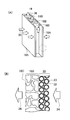
図2(A)を参照して、平膜状のセラミック濾過膜が濾過膜16として採用された場合、紙面上にて左右方向に対向する主面が濾過面16Aとなる。この濾過面16Aの全体に濾過孔が形成されている。また、濾過膜16の内部には縦方向に細長く直方体形状に伸びる多数の空隙部16B(内部空間)が形成されている。これらの空隙部16Bは、濾過膜16の上端部付近に接続するパイプと連通している。そして、濾過面16Aに形成された濾過孔は空隙部16Bと連通している。よって、濾過時には、濾過面16Aを透過した被処理水である濾過水が、空隙部16Bを経由してパイプに供給される。
上記したように、濾過膜16はセラミック等の硬質材料から成る。よって、上記した散気処理により撹拌された担体が濾過面16Aに接触しても、担体23の接触により濾過面16Aが破損することは無い。
図2(B)を参照して、図2(A)にて点線の円で囲んだ部分を拡大して示す断面図である。この図に示すように、濾過面16Aの表面に、活性汚泥を担持した担体23から成る汚泥層22が形成されても良い。この場合、濾過面16Aの閉塞を防止するために、濾過水を濾過膜16に注入して汚泥層22を濾過面16Aから離脱させる逆洗が必要となる。ここで、濾過面16Aに設けられる濾過孔16Cの大きさは、担体23よりも小さい。よって、濾過孔16Cにより濾過孔16Cが閉塞する恐れは小さい。
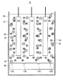
図3を参照して、排水処理装置10を更に詳述する。ここでは、処理タンク12に貯留された排水24に、複数の濾過膜16D、16E、16Fが、互いの濾過面が対向するように配置されている。複数の濾過膜を備えることで、装置全体としてのフラックスが大きく確保される。
本形態では、散気部28に設けた散気孔17A等から排水24に空気30を発生させているが、散気孔17Aの場所は、担体23の撹拌に適した箇所に配置される。
具体的には、紙面上にて最も左側に配置された濾過膜16Dと処理タンク12の側壁との間隙に、空気30が侵入するように、散気孔17Aが設けられている。即ち、散気部28の散気孔17Aは、この間隙の下方に配置されている。これにより、濾過膜16Dと処理タンクの側壁との間で、空気30が上昇し、これにより上方向に向く排水24の水流と共に、担体23も上方に移動する。よって、排水24の内部で担体23が撹拌される効果が得られる。
同様に、濾過膜16D、16Eおよび16F同士の間隙の下方に、散気孔17B、17Cが設けられている。更に、右端に配置された濾過膜16Fと処理タンク12の側壁との間隙の下方に散気孔17Dが配置されている。
上記した各図を参照して、上記した排水処理装置10を用いて排水を浄化する方法を説明する。
先ず、図1(A)を参照して、処理タンク12の内部に外部から排水24を導入する。本形態で浄化処理される排水は、下水等の有機性の被除去物が水に含まれたものである。下水そのものが処理タンク12に導入されても良いが、沈殿処理等により大型の固形物が除去処理された下水が処理タンク12に導入されても良い。処理タンク12には、下水を濾過処理するための濾過膜16が備えられており、この濾過膜16は全体的に排水24に浸漬された状態となる。
その後、排水24に担体23を導入して、散気部28から空気30を発生させる。発生される空気30の量は、通常の膜分離活性汚泥法と同程度で良い。これにより、空気30が上昇することにより、処理タンク12の内部で排水24、これに含まれる活性汚泥および担体23が撹拌される。また、空気30が排水24に散気されることにより、排水24に酸素が供給されて活性汚泥32の活動が活発に成る。これにより、担体23の表面に活性汚泥32が担持され、活性汚泥が濃縮されて処理効率が向上する。
上記したように、本形態の担体23は、比重が1よりも大きい微粒子から成るので、担体23が排水24の液面に浮上することが無く、排水24の流動と共に担体23は良好に撹拌される。
本形態では、上記したように、担体23の材料として活性炭等の硬質材料が採用されているが、濾過膜16としても硬質なセラミックが採用されているので、担体23が接触することにより濾過膜16が破損することが防止されている。
上記のように担体23に活性汚泥32が十分に担持されたら、ポンプ18で濾過膜16の内部空間に負圧を与えることにより、濾過膜16で濾過された濾過水26を系外に取り出す。ポンプ18で与えられる負圧は圧力計20で所定の範囲となるように制御される。取り出された濾過水は、その後に、沈殿処理、消毒処理等を経て外部に放出される。
10 排水処理装置
12 処理タンク
14 ポンプ
16 濾過膜
16A 濾過面
16B 空隙部
16C 濾過孔
16D,16E,16F 濾過膜
17,17A,17B,17C,17D 散気孔
18 ポンプ
20 圧力計
22 汚泥層
23 担体
24 排水
26 濾過水
28 散気部
30 空気
32 活性汚泥
12 処理タンク
14 ポンプ
16 濾過膜
16A 濾過面
16B 空隙部
16C 濾過孔
16D,16E,16F 濾過膜
17,17A,17B,17C,17D 散気孔
18 ポンプ
20 圧力計
22 汚泥層
23 担体
24 排水
26 濾過水
28 散気部
30 空気
32 活性汚泥
Claims (5)
- 活性汚泥を含む排水が貯留される処理タンクと、
前記排水に浸漬される硬質濾過膜と、
前記排水の内部にて前記硬質濾過膜の下方で気体を発生させる気体発生手段と、を備え、
水よりも比重が大きい硬質材料から成る硬質担体を前記処理タンクに収納される前記排水に添加し、前記活性汚泥は前記硬質担体に担持されることを特徴とする排水処理装置。 - 前記硬質濾過膜は、セラミックから成ることを特徴とする請求項1に記載の排水処理装置。
- 前記硬質担体は、無機材料から成ることを特徴とする請求項1に記載の排水処理装置。
- 前記硬質担体は、活性炭、ゼオライト、シリカまたは発泡ガラスから成ることを特徴とする請求項1に記載の排水処理装置。
- 前記硬質担体の幅は、0.1μm以上0.5μm以下であることを特徴とする請求項1に記載の排水処理装置。
Applications Claiming Priority (2)
| Application Number | Priority Date | Filing Date | Title |
|---|---|---|---|
| JP2013117285A JP6151578B2 (ja) | 2013-06-03 | 2013-06-03 | 排水処理装置 |
| JP2013-117285 | 2013-06-03 |
Publications (1)
| Publication Number | Publication Date |
|---|---|
| WO2014196151A1 true WO2014196151A1 (ja) | 2014-12-11 |
Family
ID=52007812
Family Applications (1)
| Application Number | Title | Priority Date | Filing Date |
|---|---|---|---|
| PCT/JP2014/002760 Ceased WO2014196151A1 (ja) | 2013-06-03 | 2014-05-26 | 排水処理装置 |
Country Status (3)
| Country | Link |
|---|---|
| JP (1) | JP6151578B2 (ja) |
| TW (1) | TWI526404B (ja) |
| WO (1) | WO2014196151A1 (ja) |
Cited By (2)
| Publication number | Priority date | Publication date | Assignee | Title |
|---|---|---|---|---|
| US9333464B1 (en) | 2014-10-22 | 2016-05-10 | Koch Membrane Systems, Inc. | Membrane module system with bundle enclosures and pulsed aeration and method of operation |
| USD779632S1 (en) | 2015-08-10 | 2017-02-21 | Koch Membrane Systems, Inc. | Bundle body |
Families Citing this family (3)
| Publication number | Priority date | Publication date | Assignee | Title |
|---|---|---|---|---|
| KR101969522B1 (ko) * | 2017-10-25 | 2019-04-16 | (주)인바이어플랜텍 | 산업폐수의 중금속 처리 시스템 |
| JP7004043B1 (ja) * | 2020-08-21 | 2022-02-10 | 株式会社明電舎 | セラミック平膜 |
| JP7004042B1 (ja) | 2020-08-21 | 2022-02-10 | 株式会社明電舎 | セラミック平膜 |
Citations (13)
| Publication number | Priority date | Publication date | Assignee | Title |
|---|---|---|---|---|
| JPH05317897A (ja) * | 1992-04-08 | 1993-12-03 | Hitachi Plant Eng & Constr Co Ltd | 汚泥消化方法 |
| JPH0924373A (ja) * | 1995-07-12 | 1997-01-28 | Kawasaki Steel Corp | 有機性物質を含む排水の処理方法および排水処理装置 |
| JPH0957292A (ja) * | 1995-08-24 | 1997-03-04 | Mitsubishi Rayon Co Ltd | 廃水処理装置 |
| JPH0957289A (ja) * | 1995-08-30 | 1997-03-04 | Mitsubishi Kakoki Kaisha Ltd | 流動床式生物処理装置 |
| JPH0966292A (ja) * | 1995-09-01 | 1997-03-11 | Kawasaki Steel Corp | 有機性物質を含む排水の処理方法 |
| JPH09150148A (ja) * | 1995-11-30 | 1997-06-10 | Mitsubishi Kakoki Kaisha Ltd | 浸漬濾過膜処理装置 |
| JPH09308883A (ja) * | 1996-05-21 | 1997-12-02 | Ebara Corp | 水の生物処理装置 |
| JPH1080624A (ja) * | 1996-09-06 | 1998-03-31 | Hitachi Plant Eng & Constr Co Ltd | 膜濾過方法 |
| JPH10314554A (ja) * | 1997-05-16 | 1998-12-02 | Hitachi Metals Ltd | 膜分離活性汚泥法 |
| JP2002361237A (ja) * | 2001-06-08 | 2002-12-17 | Ebara Corp | Cod含有排水の処理方法及び装置 |
| JP2005074357A (ja) * | 2003-09-02 | 2005-03-24 | Ngk Insulators Ltd | 膜分離活性汚泥法における膜洗浄方法 |
| JP2005230785A (ja) * | 2004-02-23 | 2005-09-02 | Sumitomo Heavy Ind Ltd | 生物学的廃水処理装置及び生物学的廃水処理方法 |
| WO2011132497A1 (ja) * | 2010-04-19 | 2011-10-27 | 株式会社明電舎 | 膜ユニット及び膜分離装置 |
Family Cites Families (9)
| Publication number | Priority date | Publication date | Assignee | Title |
|---|---|---|---|---|
| JPH0738789B2 (ja) * | 1987-03-02 | 1995-05-01 | 三機工業株式会社 | メンブレンバイオリアクタ装置 |
| FR2737202B1 (fr) * | 1995-07-25 | 1997-10-17 | Omnium Traitement Valorisa | Installation pour le traitement biologique des eaux en vue de leur potabilisation |
| JP3385306B2 (ja) * | 1997-02-28 | 2003-03-10 | 株式会社クラレ | 排水処理装置 |
| JP3142792B2 (ja) * | 1997-03-14 | 2001-03-07 | 川崎重工業株式会社 | 炭素系吸着剤を用いる廃水処理方法 |
| JP4696326B2 (ja) * | 1999-01-12 | 2011-06-08 | 栗田工業株式会社 | 超純水製造装置におけるtoc成分除去装置 |
| JP2001062488A (ja) * | 1999-08-24 | 2001-03-13 | Ebara Corp | 窒素含有廃液の処理方法及び装置 |
| JP4150975B2 (ja) * | 2004-04-21 | 2008-09-17 | 株式会社日立プラントテクノロジー | 排水処理装置 |
| WO2007086240A1 (ja) * | 2006-01-25 | 2007-08-02 | Kuraray Co., Ltd. | 固定化担体を利用した排水処理方法 |
| DE102006008453A1 (de) * | 2006-02-17 | 2007-08-23 | Itn Nanovation Ag | Reinigungsverfahren für Abwässer |
-
2013
- 2013-06-03 JP JP2013117285A patent/JP6151578B2/ja active Active
-
2014
- 2014-05-26 WO PCT/JP2014/002760 patent/WO2014196151A1/ja not_active Ceased
- 2014-05-26 TW TW103118227A patent/TWI526404B/zh not_active IP Right Cessation
Patent Citations (13)
| Publication number | Priority date | Publication date | Assignee | Title |
|---|---|---|---|---|
| JPH05317897A (ja) * | 1992-04-08 | 1993-12-03 | Hitachi Plant Eng & Constr Co Ltd | 汚泥消化方法 |
| JPH0924373A (ja) * | 1995-07-12 | 1997-01-28 | Kawasaki Steel Corp | 有機性物質を含む排水の処理方法および排水処理装置 |
| JPH0957292A (ja) * | 1995-08-24 | 1997-03-04 | Mitsubishi Rayon Co Ltd | 廃水処理装置 |
| JPH0957289A (ja) * | 1995-08-30 | 1997-03-04 | Mitsubishi Kakoki Kaisha Ltd | 流動床式生物処理装置 |
| JPH0966292A (ja) * | 1995-09-01 | 1997-03-11 | Kawasaki Steel Corp | 有機性物質を含む排水の処理方法 |
| JPH09150148A (ja) * | 1995-11-30 | 1997-06-10 | Mitsubishi Kakoki Kaisha Ltd | 浸漬濾過膜処理装置 |
| JPH09308883A (ja) * | 1996-05-21 | 1997-12-02 | Ebara Corp | 水の生物処理装置 |
| JPH1080624A (ja) * | 1996-09-06 | 1998-03-31 | Hitachi Plant Eng & Constr Co Ltd | 膜濾過方法 |
| JPH10314554A (ja) * | 1997-05-16 | 1998-12-02 | Hitachi Metals Ltd | 膜分離活性汚泥法 |
| JP2002361237A (ja) * | 2001-06-08 | 2002-12-17 | Ebara Corp | Cod含有排水の処理方法及び装置 |
| JP2005074357A (ja) * | 2003-09-02 | 2005-03-24 | Ngk Insulators Ltd | 膜分離活性汚泥法における膜洗浄方法 |
| JP2005230785A (ja) * | 2004-02-23 | 2005-09-02 | Sumitomo Heavy Ind Ltd | 生物学的廃水処理装置及び生物学的廃水処理方法 |
| WO2011132497A1 (ja) * | 2010-04-19 | 2011-10-27 | 株式会社明電舎 | 膜ユニット及び膜分離装置 |
Cited By (5)
| Publication number | Priority date | Publication date | Assignee | Title |
|---|---|---|---|---|
| US9333464B1 (en) | 2014-10-22 | 2016-05-10 | Koch Membrane Systems, Inc. | Membrane module system with bundle enclosures and pulsed aeration and method of operation |
| US9956530B2 (en) | 2014-10-22 | 2018-05-01 | Koch Membrane Systems, Inc. | Membrane module system with bundle enclosures and pulsed aeration and method of operation |
| US10702831B2 (en) | 2014-10-22 | 2020-07-07 | Koch Separation Solutions, Inc. | Membrane module system with bundle enclosures and pulsed aeration and method of operation |
| USD779632S1 (en) | 2015-08-10 | 2017-02-21 | Koch Membrane Systems, Inc. | Bundle body |
| USD779631S1 (en) | 2015-08-10 | 2017-02-21 | Koch Membrane Systems, Inc. | Gasification device |
Also Published As
| Publication number | Publication date |
|---|---|
| JP6151578B2 (ja) | 2017-06-21 |
| TW201446662A (zh) | 2014-12-16 |
| TWI526404B (zh) | 2016-03-21 |
| JP2014233686A (ja) | 2014-12-15 |
Similar Documents
| Publication | Publication Date | Title |
|---|---|---|
| WO2014196151A1 (ja) | 排水処理装置 | |
| CN104903255A (zh) | 有机排水处理装置的运转方法及有机排水处理装置 | |
| JP5128417B2 (ja) | 含油廃水処理方法 | |
| KR100827641B1 (ko) | 미세다공판을 설치한 접촉산화조 | |
| JP5853342B2 (ja) | 固液分離モジュールおよび、固液分離方法 | |
| JP2009119354A (ja) | 生物処理装置および生物処理方法 | |
| JP4591678B2 (ja) | 生物処理装置 | |
| JP3491125B2 (ja) | 浄水処理装置 | |
| JPH09308883A (ja) | 水の生物処理装置 | |
| CN213680013U (zh) | 一种活性污泥污水处理装置 | |
| JP6110216B2 (ja) | 排水処理装置 | |
| JP6267567B2 (ja) | 野菜の洗浄排水ろ過装置 | |
| JPH10165041A (ja) | 水槽の水を循環濾過するための濾過槽および濾過方法 | |
| CN104220384B (zh) | 横置型膜过滤装置 | |
| JP2003053368A (ja) | 膜分離活性汚泥処理装置 | |
| JP4181501B2 (ja) | 生物膜濾過装置及び方法 | |
| JP2003170185A (ja) | ろ過装置を備えた浄化槽及びろ材による被処理水の浄化方法 | |
| JP2021184702A (ja) | 高密度・高速成長養殖のための閉鎖循環型飼育水浄化システム | |
| JP6169907B2 (ja) | コークス炉排水の処理装置、コークス炉排水の処理方法 | |
| JP3333116B2 (ja) | 膜分離装置 | |
| JP2014240050A (ja) | 生物接触濾過装置 | |
| JP6708864B2 (ja) | Voc汚染水の浄化処理方法 | |
| JP2011056384A (ja) | 膜分離装置 | |
| JP2006055814A (ja) | 浮上分離方法及び装置 | |
| CN204058055U (zh) | 移动床生物膜反应装置 |
Legal Events
| Date | Code | Title | Description |
|---|---|---|---|
| 121 | Ep: the epo has been informed by wipo that ep was designated in this application |
Ref document number: 14806971 Country of ref document: EP Kind code of ref document: A1 |
|
| NENP | Non-entry into the national phase |
Ref country code: DE |
|
| 122 | Ep: pct application non-entry in european phase |
Ref document number: 14806971 Country of ref document: EP Kind code of ref document: A1 |