WO2014196382A1 - Dispositif d'amortissement de vibrations - Google Patents
Dispositif d'amortissement de vibrations Download PDFInfo
- Publication number
- WO2014196382A1 WO2014196382A1 PCT/JP2014/063708 JP2014063708W WO2014196382A1 WO 2014196382 A1 WO2014196382 A1 WO 2014196382A1 JP 2014063708 W JP2014063708 W JP 2014063708W WO 2014196382 A1 WO2014196382 A1 WO 2014196382A1
- Authority
- WO
- WIPO (PCT)
- Prior art keywords
- chamber
- rectifying
- liquid
- mounting member
- vibration isolator
- Prior art date
- Legal status (The legal status is an assumption and is not a legal conclusion. Google has not performed a legal analysis and makes no representation as to the accuracy of the status listed.)
- Ceased
Links
Images


Classifications
-
- F—MECHANICAL ENGINEERING; LIGHTING; HEATING; WEAPONS; BLASTING
- F16—ENGINEERING ELEMENTS AND UNITS; GENERAL MEASURES FOR PRODUCING AND MAINTAINING EFFECTIVE FUNCTIONING OF MACHINES OR INSTALLATIONS; THERMAL INSULATION IN GENERAL
- F16F—SPRINGS; SHOCK-ABSORBERS; MEANS FOR DAMPING VIBRATION
- F16F13/00—Units comprising springs of the non-fluid type as well as vibration-dampers, shock-absorbers, or fluid springs
- F16F13/04—Units comprising springs of the non-fluid type as well as vibration-dampers, shock-absorbers, or fluid springs comprising both a plastics spring and a damper, e.g. a friction damper
- F16F13/06—Units comprising springs of the non-fluid type as well as vibration-dampers, shock-absorbers, or fluid springs comprising both a plastics spring and a damper, e.g. a friction damper the damper being a fluid damper, e.g. the plastics spring not forming a part of the wall of the fluid chamber of the damper
- F16F13/08—Units comprising springs of the non-fluid type as well as vibration-dampers, shock-absorbers, or fluid springs comprising both a plastics spring and a damper, e.g. a friction damper the damper being a fluid damper, e.g. the plastics spring not forming a part of the wall of the fluid chamber of the damper the plastics spring forming at least a part of the wall of the fluid chamber of the damper
- F16F13/10—Units comprising springs of the non-fluid type as well as vibration-dampers, shock-absorbers, or fluid springs comprising both a plastics spring and a damper, e.g. a friction damper the damper being a fluid damper, e.g. the plastics spring not forming a part of the wall of the fluid chamber of the damper the plastics spring forming at least a part of the wall of the fluid chamber of the damper the wall being at least in part formed by a flexible membrane or the like
- F16F13/105—Units comprising springs of the non-fluid type as well as vibration-dampers, shock-absorbers, or fluid springs comprising both a plastics spring and a damper, e.g. a friction damper the damper being a fluid damper, e.g. the plastics spring not forming a part of the wall of the fluid chamber of the damper the plastics spring forming at least a part of the wall of the fluid chamber of the damper the wall being at least in part formed by a flexible membrane or the like characterised by features of partitions between two working chambers
- F16F13/107—Passage design between working chambers
Definitions
- the present invention relates to a vibration isolator that is applied to, for example, automobiles and industrial machines and absorbs and attenuates vibrations of a vibration generating unit such as an engine.
- a cylindrical first attachment member connected to one of the vibration generating portion and the vibration receiving portion, a second attachment member connected to the other, and both of these attachments
- An elastic body for connecting the members and a partition member that divides the liquid chamber in the first mounting member enclosing the liquid into a main liquid chamber having the elastic body as a part of a wall surface and a sub liquid chamber. Configurations with which are provided are known.
- the partition member is formed with a restriction passage that communicates the main liquid chamber and the sub liquid chamber.
- both the mounting members are relatively displaced while elastically deforming the elastic body, and the vibration is generated by changing the liquid pressure in the main liquid chamber and flowing the restricted passage through the liquid. Absorbed and attenuated.
- the main liquid chamber may become negative pressure.
- the main liquid chamber can be negatively pressured even when large amplitude vibration is input. Suppressing configurations are known.
- the valve body since the valve body is provided, the structure is complicated, and the tuning of the valve body is difficult.
- the valve body may be unexpectedly opened, which may affect the damping performance, or a desired characteristic may not be obtained when the valve body deteriorates over time.
- an abnormal sound such as a hitting sound accompanying opening and closing of the valve body is generated, which may affect the riding comfort performance.
- the present invention has been made in view of the above-described circumstances, and can be easily manufactured with a simple structure, and can exhibit stable damping performance over a long period of time while suppressing the generation of abnormal noise.
- An object is to provide a vibration isolator capable of suppressing pressure.
- a first aspect of the vibration isolator includes a cylindrical first mounting member connected to one of the vibration generating unit and the vibration receiving unit, a second mounting member connected to the other, and these An elastic body that connects the two mounting members, and a liquid chamber in the first mounting member in which a liquid is sealed, are divided into a main liquid chamber and a sub liquid chamber having the elastic body as a part of a wall surface.
- a partition member, and the partition member is formed with a restricting passage that communicates the main liquid chamber and the sub liquid chamber, and the partition member includes the main liquid chamber or
- a rectifying chamber that communicates the sub-liquid chamber and the restriction passage is provided, and the rectifying chamber rectifies the liquid into a swirling flow according to the flow velocity of the liquid flowing into the inside.
- the vibration isolator of the present invention it is possible to easily manufacture with a simple structure, and to suppress negative pressure of the main liquid chamber while exhibiting stable damping performance over a long period while suppressing the generation of abnormal noise. it can.
- FIG. 2 is a cross-sectional view taken along line AA shown in FIG.
- FIG. 3 is a cross-sectional view taken along the line BB shown in FIG. 1.
- the vibration isolator 10 includes a cylindrical first mounting member 11 connected to one of the vibration generating unit and the vibration receiving unit, and a second mounting connected to the other of the vibration generating unit and the vibration receiving unit.
- the member 12, an elastic body 13 that elastically connects the first and second mounting members 11, 12, and the interior of the first mounting member 11 are divided into a main liquid chamber 14 and a sub liquid chamber 15 described later.
- a partition member 16 Each of these members is formed in a circular shape or an annular shape when viewed from above, and is disposed coaxially with the first mounting member 11.
- the second mounting member 12 is connected to an engine as a vibration generating unit, while the first mounting member 11 is used as a vibration receiving unit via a bracket or the like (not shown).
- the vibration isolator 10 When the vibration isolator 10 is mounted on, for example, an automobile, the second mounting member 12 is connected to an engine as a vibration generating unit, while the first mounting member 11 is used as a vibration receiving unit via a bracket or the like (not shown).
- the second mounting member 12 is formed in a columnar shape, and is disposed in the first mounting member 11 at one end opening in the axial direction of the first mounting member 11.
- the elastic body 13 is bonded to one end opening of the first mounting member 11 and the outer peripheral surface of the second mounting member 12 to close the first mounting member 11 from one end side in the axial direction.
- An internal thread portion is formed on one end surface of the second mounting member 12. Further, one axial end portion of the second mounting member 12 protrudes outward in the axial direction from the one end opening surface in the axial direction of the first mounting member 11.
- a diaphragm 19 is disposed at the other end opening in the axial direction of the first mounting member 11.
- the diaphragm 19 is formed in a circular shape when viewed from above, and is an inverted rod-shaped body that opens toward the other end side in the axial direction. Further, the outer peripheral edge of the diaphragm 19 is vulcanized and bonded to the inner peripheral surface of the ring plate 19a over the entire periphery.
- the ring plate 19a is fitted into the other end opening of the first mounting member 11, so that the diaphragm 19 closes the first mounting member 11 from the other end side in the axial direction.
- the liquid chamber 17 includes a main liquid chamber 14 in which the partition member 16 has an elastic body 13 in a part of the partition wall and an internal volume is changed by deformation of the elastic body 13, and a diaphragm 19 in a part of the partition wall.
- the sub-liquid chamber 15 has an inner volume which is changed by deformation of the diaphragm 19.
- the vibration isolator 10 is a compression type that is attached and used so that the main liquid chamber 14 is positioned on the upper side in the vertical direction and the sub liquid chamber 15 is positioned on the lower side in the vertical direction.
- the partition member 16 is provided with a restriction passage 21 that communicates the main liquid chamber 14 and the sub liquid chamber 15 and a rectifying chamber 22 that communicates the main liquid chamber 14 or the sub liquid chamber 15 and the restriction passage 21.
- the restriction passage 21 has a vibration of a normal magnitude assumed to be input from the vibration generating unit, such as idle vibration (for example, a frequency of 18 Hz to 30 Hz, an amplitude of ⁇ 0.5 mm or less), or a frequency lower than that of the idle vibration.
- Liquid column resonance (resonance) is generated with respect to an input of normal vibration such as engine shake vibration (for example, frequency is 14 Hz or less and amplitude is larger than ⁇ 0.5 mm).
- the resonance frequency of the restriction passage 21 is set to the normal vibration frequency.
- the resonance frequency of the restriction passage 21 is set (tuned) based on, for example, the flow path length and the flow passage cross-sectional area of the restriction passage 21.
- the restriction passage 21 includes a circumferential groove 21 a formed on the outer peripheral surface of the partition member 16, and a communication hole 21 b that communicates the circumferential groove 21 a with the main liquid chamber 14.
- the circumferential groove 21 a extends along the circumferential direction of the first mounting member 11.
- the circumferential groove 21 a is closed from the outside in the radial direction of the first mounting member 11 by the rubber film 18 covered on the inner peripheral surface of the first mounting member 11.
- the rubber film 18 is formed integrally with the elastic body 13, and the inner peripheral surface of the first mounting member 11 is covered with the elastic body 13 and the rubber film 18 over the entire area.
- the communication hole 21b communicates one end of the circumferential end portions of the circumferential groove 21a with the main liquid chamber 14.
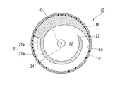
- the rectifying chamber 22 is disposed on the inner side in the radial direction than the restriction passage 21 and is disposed coaxially with the axis O of the first mounting member 11.
- the rectifying chamber 22 communicates with the auxiliary liquid chamber 15 and the restriction passage 21 and communicates with the main liquid chamber 14 through the restriction passage 21.
- a rectifying opening 23 and a circulation opening 24 are provided on the wall surface of the rectifying chamber 22 .
- the rectifying opening 23 is disposed on the inner peripheral surface of the rectifying chamber 22 and opens in the circumferential direction toward the rectifying chamber 22.
- the rectifying opening 23 communicates with the other end of the circumferential ends of the circumferential groove 21a.
- One rectifying opening 23 may be provided, and a plurality of rectifying openings 23 may be provided at intervals in the circumferential direction.
- a plurality of restriction passages 21 may be provided correspondingly.
- the distribution opening 24 is directly connected to the auxiliary liquid chamber 15.
- the circulation opening 24 opens in the rectifying chamber 22 in the axial direction, and is located on the inner side in the radial direction than the rectifying opening 23.
- the flow opening 24 is formed in a circular shape in a plan view when the vibration isolator 10 is viewed from the axial direction, and is arranged coaxially with the axis O.
- the rectifying chamber 22 rectifies the liquid L into a swirling flow according to the flow velocity of the liquid L flowing into the inside.
- the rectifying chamber 22 rectifies the liquid L flowing into the inside from the main liquid chamber 14 side into a swirling flow.
- the rectifying chamber 22 rectifies the liquid L flowing into the inside from the restriction passage 21 into a swirling flow.
- the rectifying chamber 22 rectifies the swirling flow by causing the liquid L flowing into the rectifying opening 23 to flow along the inner peripheral surface of the rectifying chamber 22.
- the liquid L rectified into the swirl flow in the rectifying chamber 22 flows out of the rectifying chamber 22 from the circulation opening 24.
- both the attachment members 11 and 12 are relatively displaced while elastically deforming the elastic body 13, so that the liquid pressure in the main liquid chamber 14 fluctuates, and the liquid in the main liquid chamber 14 changes.
- L attempts to flow between the main liquid chamber 14 and the sub liquid chamber 15 through the restriction passage 21 and the rectifying chamber 22.
- the rectifying chamber 22 rectifies the liquid L into a swirling flow according to the flow velocity of the liquid L flowing into the inside, so that when the normal vibration described above is input, the liquid L is in the rectifying chamber 22.
- the liquid L can be rectified into the swirl flow in the rectifying chamber 22 when a large vibration having an amplitude larger than the normal vibration is input while suppressing the rectification into the swirl flow.
- the liquid L when a normal vibration is input, the liquid L is prevented from being rectified into a swirling flow in the rectifying chamber 22, and the liquid L is smoothly circulated through the restriction passage 21 to effectively absorb the vibration. And can be attenuated.
- the liquid L when a large vibration is input, the liquid L is rectified into a swirl flow in the rectification chamber 22.
- pressure loss occurs in the liquid L due to centrifugal force based on this swirling flow, energy loss due to the formation of this swirling flow, energy loss due to friction between the liquid L and the wall surface of the rectifying chamber 22, and the like. As a result, the flow rate of the liquid L is reduced.
- the vibration isolator 10 As a result, it is possible to suppress the outflow of the excessive liquid L from the main liquid chamber 14 and to suppress local negative pressure in the main liquid chamber 14.
- the vibration isolator 10 there is no need to install a movable member such as the valve body shown in the prior art. Therefore, it is possible to reduce abnormal noise caused by the negative pressure in the main liquid chamber 14. That is, in the vibration isolator 10, for example, an abnormal sound accompanying the operation of the movable member, and a hitting sound generated between the movable member and the fixed member to which the movable member is fixed are not generated.
- the vibration isolator 10 by providing the rectifying chamber 22 instead of the valve body as in the prior art, this vibration is suppressed when normal vibration is input. While absorbing and attenuating, negative pressure in the main liquid chamber 14 can be suppressed when a large vibration is input. As a result, it can be easily manufactured with a simple structure and can exhibit stable damping performance over a long period of time. Therefore, it is possible to provide a vibration isolator having excellent ride comfort performance.
- the rectifying chamber 22 rectifies the liquid L flowing into the inside from the main liquid chamber 14 side into a swirling flow
- the rectifying chamber 22 turns the liquid L flowing into the inside from the sub liquid chamber 15 side into a swirling flow.
- the negative pressure in the main liquid chamber 14 can be suppressed with high responsiveness. That is, even when the liquid L flowing into the sub liquid chamber 15 from the side is rectified into a swirl flow, the resonance loss of the liquid L is reduced by causing the pressure loss in the liquid L as described above, and the liquid L It is possible to reduce the flow rate of the liquid L flowing between the liquid chambers 14 and 15 per unit time by reducing the reciprocating speed of the liquid chamber.
- the rectifying chamber 22 may rectify the liquid L flowing into the inside from the restriction passage 21 into a swirling flow.
- the rectifying chamber 22 rectifies the liquid L flowing into the inside from the restriction passage 21 into a swirling flow, the liquid L whose flow velocity and flow direction are stabilized by flowing through the restriction passage 21 It becomes possible to rectify into a swirl flow in the rectifying chamber 22, and this liquid can be accurately rectified into a swirl flow while maintaining a simple configuration.
- the rectifying chamber 22 is arranged coaxially with the first mounting member 11, and a rectifying opening 23 that opens in the circumferential direction of the first mounting member 11 toward the inside of the rectifying chamber 22 is provided on the wall surface of the rectifying chamber 22.
- the rectifying chamber 22 may rectify the liquid L that has flowed into the rectifying opening 23 along the inner peripheral surface of the rectifying chamber 22 into a swirling flow.
- the rectifying chamber 22 rectifies the liquid L that has flowed into the inside of the rectifying opening 23 into a swirling flow by flowing along the inner peripheral surface of the rectifying chamber 22, so that the liquid L can be simplified.
- the structure can reliably rectify the swirl flow.
- the wall surface of the rectifying chamber 22 is provided with a flow opening 24 through which the liquid L rectified into the swirling flow in the rectifying chamber 22 flows out of the rectifying chamber 22. It opens in the axial direction of the 1st attachment member 11, and may be located inside the radial direction of the 1st attachment member 11 rather than the rectification
- the flow opening 24 opens in the rectifying chamber 22 in the axial direction, and is positioned on the inner side in the radial direction than the rectifying opening 23, so that the flow is rectified into a swirl flow in the rectifying chamber 22.
- the liquid L can be retained in the rectifying chamber 22 for a long time until the liquid L flows out from the circulation opening 24. Thereby, the flow resistance between the main liquid chamber 14 and the sub liquid chamber 15 through the rectifying chamber 22 and the restriction passage 21 can be reliably increased.
- the flow opening 24 opens in the rectifying chamber 22 in the axial direction and is positioned on the inner side in the radial direction than the rectifying opening 23.
- the liquid rectified into the swirl flow may be changed as appropriate to another configuration for flowing out of the rectifying chamber.
- the rectifying chamber 22 rectifies the liquid L that has flowed into the inside from the restriction passage 21 into a swirl flow.
- the restriction passage is disposed so as to communicate the flow opening and the auxiliary liquid chamber, and the rectifying opening is directly connected to the main liquid chamber, and the liquid rectified into the swirl flow in the rectifying chamber is You may be comprised so that it may flow in in a restriction
- straightening chamber 22 rectifies
- the partition member may be disposed in a state where the partition member is reversed in the axial direction, and the rectifying chamber may be configured to rectify the liquid that has flowed into the sub liquid chamber side into a swirl flow.
- the generation of the swirling flow in the rectifying chamber can reduce the resonance magnification of the liquid reciprocating between the main liquid chamber and the sub liquid chamber, thereby preventing the flow velocity from increasing more than necessary.
- the rectifying chambers are installed on both sides of the main liquid chamber side and the sub liquid chamber side in the partition member, and the rectifying chambers flow into the liquid from the main liquid chamber side and from the sub liquid chamber side to the inside. Both liquids may be rectified into a swirl flow. In this case, negative pressure in the main liquid chamber can be reliably suppressed.
- the main liquid chamber 14 and the sub liquid chamber 15 have different structures, but the present invention is not limited to this, and the main liquid chamber 14 and the sub liquid chamber 15 May have the same structure.
- the compression type is shown as the vibration isolator 10
- the suspension type anti-vibration used so that the main liquid chamber 14 is positioned on the lower side in the vertical direction and the auxiliary liquid chamber 15 is positioned on the upper side in the vertical direction. It can also be applied to a vibration device.
- the vibration isolator 10 according to the present invention is not limited to use for an engine mount of a vehicle, and can be applied to other than the engine mount.
- the present invention can be applied to a mount of a generator mounted on a construction machine, or can be applied to a mount of a machine installed in a factory or the like.
- the vibration isolator of the present invention it is possible to easily manufacture with a simple structure, and to suppress negative pressure of the main liquid chamber while exhibiting stable damping performance over a long period while suppressing the generation of abnormal noise. it can.
Landscapes
- Engineering & Computer Science (AREA)
- General Engineering & Computer Science (AREA)
- Mechanical Engineering (AREA)
- Combined Devices Of Dampers And Springs (AREA)
Abstract
La présente invention concerne un dispositif d'amortissement de vibrations (10) pourvu : d'un premier élément de montage cylindrique (11) relié soit à une section de génération de vibrations soit à une section de réception de vibrations ; d'un second élément de montage (12) relié à l'autre section ; d'un corps élastique (13) servant à relier les deux éléments de montage (11, 12) ; et d'un élément de séparation (16) servant à diviser une chambre (17) de liquide, qui est située à l'intérieur du premier élément de montage (11) et dans laquelle est isolé un liquide (L), en une chambre principale (14) de liquide comportant une surface de paroi, dont une partie comprend le corps élastique (13), et en une chambre secondaire (15) de liquide. L'élément de séparation (16) comporte, formé en son sein, un passage de limitation (21) servant à raccorder la chambre principale (14) de liquide et la chambre secondaire (15) de liquide. L'élément de séparation (16) est pourvu d'une chambre de régulation d'écoulement (22) servant à raccorder la chambre principale (14) de liquide ou la chambre secondaire (15) de liquide et le passage de limitation (21). La chambre de régulation d'écoulement (22) convertit l'écoulement du liquide (L), qui s'écoule dans la chambre de régulation d'écoulement (22), en un flux turbulent conformément à la vitesse d'écoulement du liquide (L).
Applications Claiming Priority (2)
| Application Number | Priority Date | Filing Date | Title |
|---|---|---|---|
| JP2013-116891 | 2013-06-03 | ||
| JP2013116891 | 2013-06-03 |
Publications (1)
| Publication Number | Publication Date |
|---|---|
| WO2014196382A1 true WO2014196382A1 (fr) | 2014-12-11 |
Family
ID=52008033
Family Applications (1)
| Application Number | Title | Priority Date | Filing Date |
|---|---|---|---|
| PCT/JP2014/063708 Ceased WO2014196382A1 (fr) | 2013-06-03 | 2014-05-23 | Dispositif d'amortissement de vibrations |
Country Status (1)
| Country | Link |
|---|---|
| WO (1) | WO2014196382A1 (fr) |
Cited By (6)
| Publication number | Priority date | Publication date | Assignee | Title |
|---|---|---|---|---|
| EP3130819A4 (fr) * | 2014-04-08 | 2017-05-31 | Bridgestone Corporation | Dispositif d'amortissement des vibrations |
| WO2017221818A1 (fr) * | 2016-06-23 | 2017-12-28 | 株式会社ブリヂストン | Dispositif d'amortissement de vibrations |
| WO2017222014A1 (fr) * | 2016-06-22 | 2017-12-28 | 株式会社ブリヂストン | Dispositif d'amortissement de vibrations |
| EP3617546A4 (fr) * | 2017-04-27 | 2021-01-20 | Bridgestone Corporation | Dispositif d'amortissement de vibrations |
| CN113727874A (zh) * | 2019-04-17 | 2021-11-30 | 株式会社普利司通 | 隔振装置 |
| US11428290B2 (en) * | 2017-12-26 | 2022-08-30 | Prospira Corporation | Vibration isolating device |
Citations (3)
| Publication number | Priority date | Publication date | Assignee | Title |
|---|---|---|---|---|
| JPS6073147A (ja) * | 1983-09-30 | 1985-04-25 | Nissan Motor Co Ltd | 流体入りマウント装置 |
| JPS61101137U (fr) * | 1984-12-10 | 1986-06-27 | ||
| JPS6228543A (ja) * | 1985-07-25 | 1987-02-06 | コンテイネンタル・グミ−ウエルケ・アクチエンゲゼルシヤフト | 減圧減衰式弾性軸受 |
-
2014
- 2014-05-23 WO PCT/JP2014/063708 patent/WO2014196382A1/fr not_active Ceased
Patent Citations (3)
| Publication number | Priority date | Publication date | Assignee | Title |
|---|---|---|---|---|
| JPS6073147A (ja) * | 1983-09-30 | 1985-04-25 | Nissan Motor Co Ltd | 流体入りマウント装置 |
| JPS61101137U (fr) * | 1984-12-10 | 1986-06-27 | ||
| JPS6228543A (ja) * | 1985-07-25 | 1987-02-06 | コンテイネンタル・グミ−ウエルケ・アクチエンゲゼルシヤフト | 減圧減衰式弾性軸受 |
Cited By (13)
| Publication number | Priority date | Publication date | Assignee | Title |
|---|---|---|---|---|
| US9926996B2 (en) | 2014-04-08 | 2018-03-27 | Bridgestone Corporation | Vibration-damping device |
| EP3130819A4 (fr) * | 2014-04-08 | 2017-05-31 | Bridgestone Corporation | Dispositif d'amortissement des vibrations |
| US20190176605A1 (en) * | 2016-06-22 | 2019-06-13 | Bridgestone Corporation | Vibration-damping device |
| WO2017222014A1 (fr) * | 2016-06-22 | 2017-12-28 | 株式会社ブリヂストン | Dispositif d'amortissement de vibrations |
| CN109312812A (zh) * | 2016-06-22 | 2019-02-05 | 株式会社普利司通 | 防振装置 |
| EP3477149A4 (fr) * | 2016-06-22 | 2019-06-26 | Bridgestone Corporation | Dispositif d'amortissement de vibrations |
| CN109073033A (zh) * | 2016-06-23 | 2018-12-21 | 株式会社普利司通 | 隔振装置 |
| WO2017221818A1 (fr) * | 2016-06-23 | 2017-12-28 | 株式会社ブリヂストン | Dispositif d'amortissement de vibrations |
| US10760641B2 (en) | 2016-06-23 | 2020-09-01 | Bridgestone Corporation | Vibration damping device |
| EP3617546A4 (fr) * | 2017-04-27 | 2021-01-20 | Bridgestone Corporation | Dispositif d'amortissement de vibrations |
| US11448286B2 (en) | 2017-04-27 | 2022-09-20 | Prospira Corporation | Vibration-damping device |
| US11428290B2 (en) * | 2017-12-26 | 2022-08-30 | Prospira Corporation | Vibration isolating device |
| CN113727874A (zh) * | 2019-04-17 | 2021-11-30 | 株式会社普利司通 | 隔振装置 |
Similar Documents
| Publication | Publication Date | Title |
|---|---|---|
| JP6245646B2 (ja) | 防振装置 | |
| JP6395323B2 (ja) | 防振装置 | |
| JP6196682B2 (ja) | 防振装置 | |
| JP6134629B2 (ja) | 防振装置 | |
| JP6274927B2 (ja) | 防振装置 | |
| WO2014196382A1 (fr) | Dispositif d'amortissement de vibrations | |
| WO2016027606A1 (fr) | Dispositif d'amortissement des vibrations | |
| CN106460999A (zh) | 隔振装置 | |
| WO2013176117A1 (fr) | Dispositif d'amortissement de vibration | |
| WO2018198444A1 (fr) | Dispositif d'amortissement de vibrations | |
| JP7350628B2 (ja) | 防振装置 | |
| JP6355242B2 (ja) | 防振装置 | |
| JP7350627B2 (ja) | 防振装置 | |
| JP6028099B2 (ja) | 防振装置 | |
| JP7145165B2 (ja) | 防振装置 | |
| JP4906768B2 (ja) | 防振装置 | |
| KR20180064721A (ko) | 차량의 엔진 마운트 | |
| JP6674334B2 (ja) | 防振装置 | |
| JP6995113B2 (ja) | 防振装置 | |
| JP2017227295A (ja) | 防振装置 | |
| WO2018225289A1 (fr) | Dispositif anti-vibrations | |
| JP6155122B2 (ja) | 防振装置 | |
| WO2014196520A1 (fr) | Dispositif amortisseur de vibrations | |
| WO2019117062A1 (fr) | Dispositif d'amortissement de vibrations | |
| JP6654792B2 (ja) | 防振装置 |
Legal Events
| Date | Code | Title | Description |
|---|---|---|---|
| 121 | Ep: the epo has been informed by wipo that ep was designated in this application |
Ref document number: 14807729 Country of ref document: EP Kind code of ref document: A1 |
|
| NENP | Non-entry into the national phase |
Ref country code: DE |
|
| 122 | Ep: pct application non-entry in european phase |
Ref document number: 14807729 Country of ref document: EP Kind code of ref document: A1 |
|
| NENP | Non-entry into the national phase |
Ref country code: JP |