WO2014199422A1 - Dispositif de conversion de puissance - Google Patents
Dispositif de conversion de puissance Download PDFInfo
- Publication number
- WO2014199422A1 WO2014199422A1 PCT/JP2013/065915 JP2013065915W WO2014199422A1 WO 2014199422 A1 WO2014199422 A1 WO 2014199422A1 JP 2013065915 W JP2013065915 W JP 2013065915W WO 2014199422 A1 WO2014199422 A1 WO 2014199422A1
- Authority
- WO
- WIPO (PCT)
- Prior art keywords
- power
- voltage
- power converter
- converter
- power generation
- Prior art date
- Legal status (The legal status is an assumption and is not a legal conclusion. Google has not performed a legal analysis and makes no representation as to the accuracy of the status listed.)
- Ceased
Links
Images




Classifications
-
- H—ELECTRICITY
- H02—GENERATION; CONVERSION OR DISTRIBUTION OF ELECTRIC POWER
- H02M—APPARATUS FOR CONVERSION BETWEEN AC AND AC, BETWEEN AC AND DC, OR BETWEEN DC AND DC, AND FOR USE WITH MAINS OR SIMILAR POWER SUPPLY SYSTEMS; CONVERSION OF DC OR AC INPUT POWER INTO SURGE OUTPUT POWER; CONTROL OR REGULATION THEREOF
- H02M7/00—Conversion of AC power input into DC power output; Conversion of DC power input into AC power output
- H02M7/42—Conversion of DC power input into AC power output without possibility of reversal
- H02M7/44—Conversion of DC power input into AC power output without possibility of reversal by static converters
- H02M7/48—Conversion of DC power input into AC power output without possibility of reversal by static converters using discharge tubes with control electrode or semiconductor devices with control electrode
- H02M7/483—Converters with outputs that each can have more than two voltages levels
- H02M7/49—Combination of the output voltage waveforms of a plurality of converters
-
- H—ELECTRICITY
- H02—GENERATION; CONVERSION OR DISTRIBUTION OF ELECTRIC POWER
- H02J—ELECTRIC POWER NETWORKS; CIRCUIT ARRANGEMENTS OR SYSTEMS FOR SUPPLYING OR DISTRIBUTING ELECTRIC POWER; SYSTEMS FOR STORING ELECTRIC ENERGY
- H02J2101/00—Supply or distribution of decentralised, dispersed or local electric power generation
- H02J2101/20—Dispersed power generation using renewable energy sources
- H02J2101/22—Solar energy
- H02J2101/24—Photovoltaics
-
- H—ELECTRICITY
- H02—GENERATION; CONVERSION OR DISTRIBUTION OF ELECTRIC POWER
- H02J—ELECTRIC POWER NETWORKS; CIRCUIT ARRANGEMENTS OR SYSTEMS FOR SUPPLYING OR DISTRIBUTING ELECTRIC POWER; SYSTEMS FOR STORING ELECTRIC ENERGY
- H02J3/00—Circuit arrangements for AC mains or AC distribution networks
- H02J3/38—Arrangements for feeding a single network from two or more generators or sources in parallel; Arrangements for feeding already energised networks from additional generators or sources in parallel
- H02J3/381—Dispersed generators
-
- Y—GENERAL TAGGING OF NEW TECHNOLOGICAL DEVELOPMENTS; GENERAL TAGGING OF CROSS-SECTIONAL TECHNOLOGIES SPANNING OVER SEVERAL SECTIONS OF THE IPC; TECHNICAL SUBJECTS COVERED BY FORMER USPC CROSS-REFERENCE ART COLLECTIONS [XRACs] AND DIGESTS
- Y02—TECHNOLOGIES OR APPLICATIONS FOR MITIGATION OR ADAPTATION AGAINST CLIMATE CHANGE
- Y02E—REDUCTION OF GREENHOUSE GAS [GHG] EMISSIONS, RELATED TO ENERGY GENERATION, TRANSMISSION OR DISTRIBUTION
- Y02E10/00—Energy generation through renewable energy sources
- Y02E10/50—Photovoltaic [PV] energy
- Y02E10/56—Power conversion systems, e.g. maximum power point trackers
Definitions
- the present invention relates to a power conversion device used in a power generation system such as a solar power generation system.
- a power converter included in a power conversion device of a power generation system such as a solar power generation system is a device that converts generated power from direct current to alternating current. There is an upper limit and a lower limit in the DC voltage applied to the power converter.
- the upper limit exists because the breakdown voltage is determined for each element in the power converter, and when the voltage applied to the power converter is increased, the element characteristics are restricted due to the use of the high breakdown voltage element. This is because an increase in switching loss of the switching element, an increase in AC reactor ACL iron loss due to an increase in current ripple, and the like occur. Therefore, it is necessary to suppress the applied voltage and avoid these disadvantages.
- Patent Document 1 a method of reducing the voltage applied to each power converter by multi-stage power converters in the power converter and avoiding the above-mentioned problem is known (for example, Patent Document 1). .
- Patent Document 1 As shown in FIG. 1 and the like of the same document, a plurality of power converters having different applied voltages are connected in series, and charging is performed from a power converter having a high applied voltage.
- the DC voltage of the converter is kept constant and the above-mentioned problems are solved.
- the power conversion device of the present invention By using the power conversion device of the present invention, a power conversion device having high power conversion efficiency, small size and low cost can be obtained.
- FIG. 1 is a schematic circuit diagram of a power conversion device according to Embodiment 1.
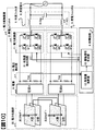
- FIG. 1 is a detailed circuit diagram of a power conversion apparatus according to Embodiment 1.
- FIG. FIG. 6 is a schematic circuit diagram of a power conversion device according to a fifth embodiment. The operation
- FIG. FIG. 10 is a schematic circuit diagram of a power conversion apparatus according to a seventh embodiment.
- FIG. 1 shows a power conversion apparatus 1 according to the first embodiment.
- the power conversion device 1 includes a power generation unit A 2, a power generation unit B 3, a control circuit 4, and a smoothing filter 5.
- the power converter device 1 is connected to AC power 6 (Vac), and the power output from the power converter device 1 to the AC power 6 is sent to a load connected to a household outlet or a power system.
- the smoothing filter 5 includes an AC reactor ACL7 and a power storage element Cac8.
- the smoothing filter 5 and the AC power 6 can be combined and replaced with a motor.
- the power generation unit A 2 includes a power source 9, a voltage detector 10, and a power converter 11A.
- the power source 9 converts the electrical energy generated inside or the electrical energy stored inside into a DC voltage and applies it to the power converter 11A.
- the voltage detector 10 detects the DC voltage value Vca applied to the power converter 11A and sends it to the control amount calculator 12 in the control circuit 4.
- the power generation unit B 3 has the same configuration as the power generation unit A 2, and the DC voltage value Vcb detected by the voltage detector 10 in the power generation unit B 3 is sent to the control amount calculator 12 in the control circuit 4. .
- the power converter in the power generation unit B ⁇ ⁇ ⁇ ⁇ 3 is referred to as a power converter 11B, and the power converters 11A and 11B may be collectively referred to as the power converter 11.
- the control amount calculator 12 calculates the control amount 17 of the power converter 11 based on the DC voltage value (Vca, Vcb) sent from each voltage detector 10 and sends it to the drive signal generator 13.
- the system voltage Vac is also sent to the control amount calculator 12 to cooperate with the system, and the control amount 17 is calculated.
- a voltage command value Vref which is a target value of the DC voltage values Vca and Vcb is set in advance.
- the voltage command value Vref may be given from the outside.
- a control amount capable of equally controlling the total value of the power and the power output by the power conversion device 1 is obtained.
- the drive signal generator 13 generates a drive signal for driving each switching element (Q1 to Q8) in the power converter 11 from the control amount 17 sent from the control amount calculator 12, and each power converter Send to 11.
- the power converter 11 receives the drive signal from the control circuit 4 and drives each switching element (Q1 to Q8).
- each switching element Q1 to Q8.
- a driver circuit necessary for driving each switching element, an auxiliary power source necessary for driving the driver circuit, and the like are not illustrated, but these are included in the power converter 11.
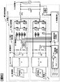
- FIG. 6 shows FIG. 1 in more detail.
- the power source 9 includes a power generator 20, a converter 21, and a storage element Ca ⁇ ⁇ 22.
- the generator 20 may be a generator that converts external energy into electric energy, such as a solar panel, a thermoelectric conversion element, or a wind power generator, or a secondary battery such as a lead battery or a lithium battery.
- the converter 21 assumes the DC-DC converter, when the electric power generated by the generator 20 is AC, it may be an AC-DC converter.
- the converter 21 may be an insulating type or a non-insulating type, and may be a unidirectional operation or a bidirectional operation.
- an insulating means 23 is appropriately provided between the control circuit 4 and the voltage detection means 10, between the control circuit 4 and the power converter 11, and between the control circuit 4 and the AC power 6.
- the negative side potential of the power generation unit B 3 is equal to the negative side potential of the control circuit 4
- the DC voltage value Vcb, the drive signal for Q7, and the signal line of the drive signal for Q8 are insulated.
- the installation location of the insulating element 23 is not limited to this example.
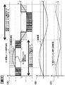
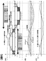
- FIG. 2 showing an operation waveform for one cycle of the commercial frequency of the AC power 6.
- each power generation unit is controlled so that the average value of the voltage obtained by superimposing the output voltage waveform 15 and the output voltage waveform 16 matches the AC voltage waveform Vac 14, specifically, the power generation unit A
- the switching elements Q1 to Q8 in each power converter 11 are controlled so that the voltage value Vca detected at 2 and the voltage value Vcb detected at the power generation unit B 3 are substantially equal to the voltage command value Vref.
- FIG. 2B shows the control amount 17 that the control amount calculator 12 outputs to the drive signal generator 13.
- FIG. 2C shows a control amount Vba 18 relating to the power balance.
- the control amount Vba 18 relating to the power balance is a positive value at time t0. This indicates that the DC voltage value Vcb is larger than Vca and the balance between the two is lost.
- the output power of the power generation unit B 3 is Control is performed so that the output power of A 2 is greater.
- the power generation unit B 3 is operated in a one-pulse mode described later, and the power generation unit A 2 is operated in a chopper mode described later.
- Vcb can be brought close to the voltage command value Vref, and as a result, the control amount Vba 18 related to the power balance can be reduced.
- the “one pulse mode” in this embodiment means that the output of the power converter is zero (short circuit) when the AC voltage waveform is less than the applied voltage of the power converter (Vca for A), and the AC voltage is converted into power. If the voltage is higher than the converter, the output of the power converter is the mode to output the applied voltage of the power converter.
- the “chopper mode” is zero (short circuit) the output voltage of the power converter in a cycle corresponding to the switching frequency. And a voltage applied to the power converter (Vcb for B) are alternately output.
- the power generation unit B 3 operating in the one-pulse mode maintains the short-circuit state with the switching elements Q5 and Q6 on and Q7 and Q8 off.
- the voltage is maintained at zero (short circuit), and from t1 to t2, the output voltage of the power generation unit B is maintained at Vcb by maintaining the voltage application state in which Q5 and Q8 are on and Q6 and Q7 are off.
- the power generation unit A 2 operating in the chopper mode has a voltage application state in which the switching elements Q1 and Q4 are turned on, Q2 and Q3 are turned off according to the controlled variable 17, and the switching elements Q1 and Q2 are turned on from t0 to t3.
- the voltage application ratio of the power generation unit A 2 is controlled so as to be linked to the control amount 17 (duty) at times t0 to t1 and t2 to t3, and from the control amount 17 at times t1 to t2.
- the voltage application ratio of the power generation unit A 2 is controlled so as to be interlocked with the control amount 19 (duty-1) obtained by dividing 1.
- the power generation unit A 2 outputs power in the chopper mode according to the control amount 17 or 19 during the period from t0 to t3.
- the power generation unit B 3 does not output power during the period from t0 to t1 and t2 to t3, and always outputs power in the one-pulse mode during the period from t1 to t2.
- the power conversion device 1 outputs power in which the output power of both power generation units is superimposed.
- the output power ratio in the one-pulse mode and the chopper mode is determined by the magnitude relationship between Vac and Vca or Vcb.
- the output power in the one-pulse mode is larger than the output power in the chopper mode.
- the control amount 18 relating to the power balance is positive at the time t0
- the DC voltage value Vcb rapidly decreases by using the one-pulse mode for the power generation unit B 3.
- the DC voltage value Vca becomes relatively large
- the power generation unit A 2 is operated in the chopper mode and the power generation unit B 3 is operated in the one-pulse mode even after the time t3, the power balance of both power generation units deteriorates in the opposite direction from the initial time.
- Vba is not calculated as a simple difference, but Vba may be obtained by calculation such as PI control, or Vba and Vcb may be read and Vba calculated at any timing within a half cycle.
- the operation of the power conversion device 1 from time t3 to t6 will be described.
- the control amount 18 relating to the power balance is negative, so it can be determined that Vca is excessive. That is, in order to promote the power output from the power generation unit A 2 and suppress the power output from the power generation unit B 3, the power generation unit A 2 needs to operate in the one-pulse mode, and the power generation unit B 3 needs to be operated in the chopper mode. is there.
- the operation from time t3 to t6 is almost the same as t0 to t3, but reverse voltage is applied. That is, the power generation unit A 2 turns on Q1 and Q2 when short-circuited, and turns on Q2 and Q3 when voltage is applied. Power generation unit B 3 turns on Q5 and Q6 when short-circuited, and turns on Q6 and Q7 when voltage is applied.
- a plurality of power generation units connected in series have the same configuration, and the voltages Vca and Vcb applied to each power converter 11 are reduced to a fraction of the number in series. Therefore, an equivalent low withstand voltage switching element can be used as the switching element of each power converter.
- the generated power amount of the power generator 20 and the output power amount of the power converter 11 are equalized by the control at the times t1 to t6 described above, so that all the generated power is supplied to each power generation unit. Can be output outside. That is, since charging / discharging does not generate
- the control of the present embodiment may be applied to a power conversion apparatus configured to connect three or more power generation units in series and output a voltage of four levels or more.
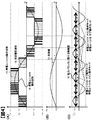
- FIG. 3 shows an operation waveform of the power conversion device according to the second embodiment.
- the second embodiment is a mode in which the relationship between the control amount and the drive signal in the drive signal generator 13 in the first embodiment is changed, and the description of common points is omitted.
- the operations of the power generation unit A 2 and the power generation unit B 3 are divided into a main operation mode and a sub operation mode.
- the main operation mode is an operation mode that outputs relatively large power
- the sub operation mode is an operation mode that outputs relatively small power.
- the power converter 11B in the chopper mode outputs larger power than the non-operating power converter 11A, and from t1 to t2, one pulse is output.
- the power converter 11B in the mode outputs larger power than the power converter 11A in the chopper mode, and the power converter 11B in the chopper mode is larger than the power converter 11A that is not operating from t2 to t3. Power is being output.
- the main operation mode is an operation mode that operates in the chopper mode during the period from t0 to t1, the one-pulse mode during the period from t1 to t2, and the chopper mode during the period from t2 to t3.
- the sub operation mode is an operation mode that operates in a short circuit during a period from t0 to t1, a chopper mode during a period from t1 to t2, and a short circuit during a period from t2 to t3.
- the power generation unit B 3 chops when the control amount Duty is 0 or more and less than 1.
- the power generation unit A 2 operates in the chopper mode at a rate of Duty-1 when the control amount is 1 or more. That is, the period from t0 to t1 and the period from t2 to t3 is short-circuited, and the period from t1 to t2 is operated in the chopper mode.
- the power generation unit B 3 driven in the main operation mode can supply power from t0 to t3, and the power generation unit A 2 driven in the sub operation mode has a period of t1 to t2. Since the power of the part is supplied, even if the power generation amount balance between the power generation unit A 2 and the power generation unit B 3 is greatly broken, it can be dealt with.
- the power converter When the control amount 18 related to the power balance is reversed as shown in FIG. 3, the power converter outputs power with a desired power balance by switching between the main operation mode and the sub operation mode as in the first embodiment. It is possible.
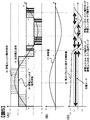
- FIG. 4 shows operation waveforms of the power conversion device of Example 3.
- the third embodiment is a mode in which the operation mode switching timing in the drive signal generator 13 in the second embodiment is changed, and the description of common points is omitted.
- Example 1 and Example 2 the operation mode was switched at a timing when Vac became substantially zero.
- the operation mode is switched when the control amount 18 relating to the power balance is switched between positive and negative.
- the timing for switching the operation mode of power generation unit A 2 and power generation unit B 3 must be when the switching state of each power converter is equal. For example, if both power converters are in a short circuit state, they are switched when Q1, Q2, Q5, and Q6 are on. If both power converters are in a positive voltage application state, they are switched when Q1, Q4, Q5 and Q8 are on. If both power converters are in a negative voltage application state, they are switched when Q2, Q3, Q6 and Q7 are on.
- FIG. 5 shows operation waveforms of the power conversion device of Example 4.
- the fourth embodiment is a mode in which charging mode switching control is added to the drive signal generator 13 of the third embodiment, and the description of common points is omitted.
- a threshold value Vth is provided for the control amount related to the power balance, and the threshold value is exceeded from t0 to t7. At this time, the power conversion device operates in the charging mode.
- the operation of the charging mode will be described.
- charging is possible from the power generation unit B 2 operating in the main operation mode to the power generation unit A 3 operating in the sub operation mode. Therefore, the power generation unit B 2 applies a voltage, and the power generation unit A 3 applies a reverse voltage.
- the power generation unit B ⁇ 3 is charged from the power generation unit B 3 during the period from t0 to t1.
- the power generation unit A 2 performs a chopper operation, but the reverse voltage is applied, so the duty is inverted. That is, in the duty ratio, Q1 and Q2 are in the short-circuit mode in the on state, and in the ratio of 1-Duty, the reverse voltage application mode is in which the Q2 and Q3 are in the on state.
- charge mode is operated with reverse voltage. Since the power generation unit A 2 operates in the main operation mode, Q6 and Q7 are turned on to apply a reverse voltage, and the power generation unit B 3 operates in a chopper mode in which a positive voltage is applied at a rate of 1-Duty.
- timing for switching to the charging mode and the timing for switching from the charging mode are preferably performed when the switching state of each power converter is equal.
- FIG. 7 shows operation waveforms of the power conversion device of Example 5.
- the fifth embodiment is a mode in which the power supply circuit 30 to the power source A and the power source B and the state quantity detector 31 of the power converter of the first embodiment are added, and the description of common points is omitted.
- a generator 20, a power source C32, and an insulating transformer 33 are provided in the power supply unit.
- the power source A and the power source B receive the power generated by the generator from the power source C.
- the distribution of power to be sent to the power source A and the power source B can be adjusted by the power source. However, even if the power source A and the power source B do not control the power distribution, the power can be freely distributed if the power converter performs the mode switching control of the present embodiment.
- the power converter when the power converter generates a calorific value of the power converter to the control circuit via the state quantity detector 31, the power output from the power converter having a large calorific value is reduced, and the power conversion with a small calorific value is performed. It is possible to increase the power output from the instrument.
- heat dispersion control can be realized, which can contribute to downsizing of the cooling mechanism such as fans and fins, downsizing of the housing, and cost reduction.
- FIG. 8 shows operation waveforms of the power conversion device of Example 6.
- the sixth embodiment is an embodiment where the power generation unit of the second embodiment has three stages, and the description of common points is omitted.
- the DC voltage applied to each power converter is a substantially equal value, and the peak voltage of the load power is a value that is 2 times or more and 3 times or less.
- the control amount related to the power balance compares the applied voltage of each power converter, and assigns the main operation mode, sub 1 operation mode, and sub 2 operation mode in the order of the power generation unit that wants to output power.
- FIG. 8C shows only the control amount Vba_bc related to the power balance between the power generation unit B 3 and the power generation unit C ⁇ .
- the power generation unit A is set to the sub-2 operation mode. Since Vba_bc is inverted in the second half cycle, the main operation mode and the sub 1 operation mode are switched.
- the control amount 17 is a value of 3 or less.
- the duty is 1 or less
- the power converter in the sub 1 operation mode performs the chopper operation according to Duty-1.
- the duty is 2 or more
- the generator can be driven with an arbitrary power balance even when there are three or more stages.
- FIG. 10 is a schematic circuit diagram of the power conversion apparatus according to the seventh embodiment.
- Example 7 is an example of the solar panel of Example 1, in which the power supply unit 30 has a multilayer structure.
- a solar panel is manufactured as a structure of two or more layers, the excitation levels of the A layer and the B layer are different, and the B layer generates a part of the spectrum of the light transmitted through the A layer.
- the power balance of the inverters shown in the first to sixth embodiments is set to a desired balance.
Landscapes
- Engineering & Computer Science (AREA)
- Power Engineering (AREA)
- Inverter Devices (AREA)
- Dc-Dc Converters (AREA)
Abstract
L'invention concerne un dispositif de conversion de puissance ayant un haut rendement de conversion de puissance. Ce dispositif de conversion de puissance comprend une pluralité de sources d'énergie qui produisent un courant continu, et une pluralité de convertisseurs de puissance qui sont disposés de manière à correspondre auxdites sources d'énergie et qui convertissent le courant continu en courant alternatif. Le dispositif de conversion de puissance peut produire une pluralité de niveaux de tension en superposant la puissance de sortie de la pluralité de convertisseurs de puissance, et commande la distribution de puissance circulant dans chaque convertisseur de puissance en commutant leurs modes de fonctionnement.
Priority Applications (2)
| Application Number | Priority Date | Filing Date | Title |
|---|---|---|---|
| JP2015522271A JPWO2014199422A1 (ja) | 2013-06-10 | 2013-06-10 | 電力変換装置 |
| PCT/JP2013/065915 WO2014199422A1 (fr) | 2013-06-10 | 2013-06-10 | Dispositif de conversion de puissance |
Applications Claiming Priority (1)
| Application Number | Priority Date | Filing Date | Title |
|---|---|---|---|
| PCT/JP2013/065915 WO2014199422A1 (fr) | 2013-06-10 | 2013-06-10 | Dispositif de conversion de puissance |
Publications (1)
| Publication Number | Publication Date |
|---|---|
| WO2014199422A1 true WO2014199422A1 (fr) | 2014-12-18 |
Family
ID=52021758
Family Applications (1)
| Application Number | Title | Priority Date | Filing Date |
|---|---|---|---|
| PCT/JP2013/065915 Ceased WO2014199422A1 (fr) | 2013-06-10 | 2013-06-10 | Dispositif de conversion de puissance |
Country Status (2)
| Country | Link |
|---|---|
| JP (1) | JPWO2014199422A1 (fr) |
| WO (1) | WO2014199422A1 (fr) |
Cited By (1)
| Publication number | Priority date | Publication date | Assignee | Title |
|---|---|---|---|---|
| JP2023177345A (ja) * | 2022-06-01 | 2023-12-13 | ミルウォーキー エレクトリック ツール コーポレイション | カスケード式インバータを含む電力供給装置 |
Citations (7)
| Publication number | Priority date | Publication date | Assignee | Title |
|---|---|---|---|---|
| JPH08186984A (ja) * | 1994-12-28 | 1996-07-16 | Nissan Motor Co Ltd | インバータのフェールセーフ装置 |
| JP2006320103A (ja) * | 2005-05-12 | 2006-11-24 | Fuji Electric Systems Co Ltd | 直列多重電力変換装置の制御装置 |
| JP2010142085A (ja) * | 2008-12-15 | 2010-06-24 | Omron Corp | パワーコンディショナ |
| WO2010086929A1 (fr) * | 2009-01-29 | 2010-08-05 | 三菱電機株式会社 | Dispositif de conversion de puissance |
| WO2011033698A1 (fr) * | 2009-09-16 | 2011-03-24 | 三菱電機株式会社 | Convertisseur de puissance |
| JP2012065437A (ja) * | 2010-09-15 | 2012-03-29 | Toshiba Corp | 電力変換装置 |
| WO2013080469A1 (fr) * | 2011-11-29 | 2013-06-06 | パナソニック 株式会社 | Dispositif de conversion électrique |
-
2013
- 2013-06-10 WO PCT/JP2013/065915 patent/WO2014199422A1/fr not_active Ceased
- 2013-06-10 JP JP2015522271A patent/JPWO2014199422A1/ja active Pending
Patent Citations (7)
| Publication number | Priority date | Publication date | Assignee | Title |
|---|---|---|---|---|
| JPH08186984A (ja) * | 1994-12-28 | 1996-07-16 | Nissan Motor Co Ltd | インバータのフェールセーフ装置 |
| JP2006320103A (ja) * | 2005-05-12 | 2006-11-24 | Fuji Electric Systems Co Ltd | 直列多重電力変換装置の制御装置 |
| JP2010142085A (ja) * | 2008-12-15 | 2010-06-24 | Omron Corp | パワーコンディショナ |
| WO2010086929A1 (fr) * | 2009-01-29 | 2010-08-05 | 三菱電機株式会社 | Dispositif de conversion de puissance |
| WO2011033698A1 (fr) * | 2009-09-16 | 2011-03-24 | 三菱電機株式会社 | Convertisseur de puissance |
| JP2012065437A (ja) * | 2010-09-15 | 2012-03-29 | Toshiba Corp | 電力変換装置 |
| WO2013080469A1 (fr) * | 2011-11-29 | 2013-06-06 | パナソニック 株式会社 | Dispositif de conversion électrique |
Cited By (2)
| Publication number | Priority date | Publication date | Assignee | Title |
|---|---|---|---|---|
| JP2023177345A (ja) * | 2022-06-01 | 2023-12-13 | ミルウォーキー エレクトリック ツール コーポレイション | カスケード式インバータを含む電力供給装置 |
| JP7559140B2 (ja) | 2022-06-01 | 2024-10-01 | ミルウォーキー エレクトリック ツール コーポレイション | カスケード式インバータを含む電力供給装置 |
Also Published As
| Publication number | Publication date |
|---|---|
| JPWO2014199422A1 (ja) | 2017-02-23 |
Similar Documents
| Publication | Publication Date | Title |
|---|---|---|
| US10581361B2 (en) | Multiple inverter system for an electric machine | |
| JP6552739B2 (ja) | 並列電源装置 | |
| US9728965B2 (en) | Scalable universal power supply and power converter | |
| CN102843028B (zh) | Dc电源系统 | |
| US10784704B2 (en) | On-board charging system | |
| JP6062058B2 (ja) | 電力変換装置 | |
| JP6124262B2 (ja) | 電源装置 | |
| JP6223609B2 (ja) | Dc/dcコンバータ | |
| JP2012210104A (ja) | 電力変換装置 | |
| JP6482676B2 (ja) | 電源装置及びその制御方法 | |
| JP2012010532A (ja) | 電力変換装置 | |
| JP6126467B2 (ja) | 電源装置 | |
| JP2014239579A (ja) | Dc/dcコンバータおよびバッテリ充放電装置 | |
| KR20190115364A (ko) | 단상 및 3상 겸용 충전기 | |
| JP5047210B2 (ja) | 電力変換装置 | |
| WO2020217721A1 (fr) | Dispositif d'alimentation électrique | |
| Monteiro et al. | A Proposed Bidirectional Three-Level dc-dc Power Converter for Applications in Smart Grids: An Experimental Validation | |
| Joshi et al. | Analysis of a new symmetic multilevel inverter topology with reduced component count | |
| Ahn et al. | A novel parallel control for modular energy storage system achieving high performance, redundancy and applicability | |
| WO2014199422A1 (fr) | Dispositif de conversion de puissance | |
| WO2013179771A1 (fr) | Dispositif convertisseur et dispositif d'entraînement de moteur utilisant celui-ci | |
| JP7500716B2 (ja) | 直流給配電システム | |
| Shehada et al. | Multilevel converter for variable speed medium-voltage switched reluctance motor drives | |
| JP2009207251A (ja) | 負荷駆動システム | |
| JP5348484B2 (ja) | 負荷駆動システム |
Legal Events
| Date | Code | Title | Description |
|---|---|---|---|
| 121 | Ep: the epo has been informed by wipo that ep was designated in this application |
Ref document number: 13886985 Country of ref document: EP Kind code of ref document: A1 |
|
| ENP | Entry into the national phase |
Ref document number: 2015522271 Country of ref document: JP Kind code of ref document: A |
|
| NENP | Non-entry into the national phase |
Ref country code: DE |
|
| 122 | Ep: pct application non-entry in european phase |
Ref document number: 13886985 Country of ref document: EP Kind code of ref document: A1 |