WO2014199423A1 - Élément d'acier et procédé de production d'élément d'acier - Google Patents
Élément d'acier et procédé de production d'élément d'acier Download PDFInfo
- Publication number
- WO2014199423A1 WO2014199423A1 PCT/JP2013/065916 JP2013065916W WO2014199423A1 WO 2014199423 A1 WO2014199423 A1 WO 2014199423A1 JP 2013065916 W JP2013065916 W JP 2013065916W WO 2014199423 A1 WO2014199423 A1 WO 2014199423A1
- Authority
- WO
- WIPO (PCT)
- Prior art keywords
- layer
- steel
- layers
- carbon concentration
- powder
- Prior art date
- Legal status (The legal status is an assumption and is not a legal conclusion. Google has not performed a legal analysis and makes no representation as to the accuracy of the status listed.)
- Ceased
Links
Images



Classifications
-
- C—CHEMISTRY; METALLURGY
- C23—COATING METALLIC MATERIAL; COATING MATERIAL WITH METALLIC MATERIAL; CHEMICAL SURFACE TREATMENT; DIFFUSION TREATMENT OF METALLIC MATERIAL; COATING BY VACUUM EVAPORATION, BY SPUTTERING, BY ION IMPLANTATION OR BY CHEMICAL VAPOUR DEPOSITION, IN GENERAL; INHIBITING CORROSION OF METALLIC MATERIAL OR INCRUSTATION IN GENERAL
- C23C—COATING METALLIC MATERIAL; COATING MATERIAL WITH METALLIC MATERIAL; SURFACE TREATMENT OF METALLIC MATERIAL BY DIFFUSION INTO THE SURFACE, BY CHEMICAL CONVERSION OR SUBSTITUTION; COATING BY VACUUM EVAPORATION, BY SPUTTERING, BY ION IMPLANTATION OR BY CHEMICAL VAPOUR DEPOSITION, IN GENERAL
- C23C8/00—Solid state diffusion of only non-metal elements into metallic material surfaces; Chemical surface treatment of metallic material by reaction of the surface with a reactive gas, leaving reaction products of surface material in the coating, e.g. conversion coatings, passivation of metals
- C23C8/60—Solid state diffusion of only non-metal elements into metallic material surfaces; Chemical surface treatment of metallic material by reaction of the surface with a reactive gas, leaving reaction products of surface material in the coating, e.g. conversion coatings, passivation of metals using solids, e.g. powders, pastes
- C23C8/62—Solid state diffusion of only non-metal elements into metallic material surfaces; Chemical surface treatment of metallic material by reaction of the surface with a reactive gas, leaving reaction products of surface material in the coating, e.g. conversion coatings, passivation of metals using solids, e.g. powders, pastes only one element being applied
- C23C8/64—Carburising
- C23C8/66—Carburising of ferrous surfaces
-
- C—CHEMISTRY; METALLURGY
- C23—COATING METALLIC MATERIAL; COATING MATERIAL WITH METALLIC MATERIAL; CHEMICAL SURFACE TREATMENT; DIFFUSION TREATMENT OF METALLIC MATERIAL; COATING BY VACUUM EVAPORATION, BY SPUTTERING, BY ION IMPLANTATION OR BY CHEMICAL VAPOUR DEPOSITION, IN GENERAL; INHIBITING CORROSION OF METALLIC MATERIAL OR INCRUSTATION IN GENERAL
- C23C—COATING METALLIC MATERIAL; COATING MATERIAL WITH METALLIC MATERIAL; SURFACE TREATMENT OF METALLIC MATERIAL BY DIFFUSION INTO THE SURFACE, BY CHEMICAL CONVERSION OR SUBSTITUTION; COATING BY VACUUM EVAPORATION, BY SPUTTERING, BY ION IMPLANTATION OR BY CHEMICAL VAPOUR DEPOSITION, IN GENERAL
- C23C4/00—Coating by spraying the coating material in the molten state, e.g. by flame, plasma or electric discharge
- C23C4/04—Coating by spraying the coating material in the molten state, e.g. by flame, plasma or electric discharge characterised by the coating material
- C23C4/06—Metallic material
-
- C—CHEMISTRY; METALLURGY
- C23—COATING METALLIC MATERIAL; COATING MATERIAL WITH METALLIC MATERIAL; CHEMICAL SURFACE TREATMENT; DIFFUSION TREATMENT OF METALLIC MATERIAL; COATING BY VACUUM EVAPORATION, BY SPUTTERING, BY ION IMPLANTATION OR BY CHEMICAL VAPOUR DEPOSITION, IN GENERAL; INHIBITING CORROSION OF METALLIC MATERIAL OR INCRUSTATION IN GENERAL
- C23C—COATING METALLIC MATERIAL; COATING MATERIAL WITH METALLIC MATERIAL; SURFACE TREATMENT OF METALLIC MATERIAL BY DIFFUSION INTO THE SURFACE, BY CHEMICAL CONVERSION OR SUBSTITUTION; COATING BY VACUUM EVAPORATION, BY SPUTTERING, BY ION IMPLANTATION OR BY CHEMICAL VAPOUR DEPOSITION, IN GENERAL
- C23C24/00—Coating starting from inorganic powder
- C23C24/02—Coating starting from inorganic powder by application of pressure only
- C23C24/04—Impact or kinetic deposition of particles
-
- C—CHEMISTRY; METALLURGY
- C23—COATING METALLIC MATERIAL; COATING MATERIAL WITH METALLIC MATERIAL; CHEMICAL SURFACE TREATMENT; DIFFUSION TREATMENT OF METALLIC MATERIAL; COATING BY VACUUM EVAPORATION, BY SPUTTERING, BY ION IMPLANTATION OR BY CHEMICAL VAPOUR DEPOSITION, IN GENERAL; INHIBITING CORROSION OF METALLIC MATERIAL OR INCRUSTATION IN GENERAL
- C23C—COATING METALLIC MATERIAL; COATING MATERIAL WITH METALLIC MATERIAL; SURFACE TREATMENT OF METALLIC MATERIAL BY DIFFUSION INTO THE SURFACE, BY CHEMICAL CONVERSION OR SUBSTITUTION; COATING BY VACUUM EVAPORATION, BY SPUTTERING, BY ION IMPLANTATION OR BY CHEMICAL VAPOUR DEPOSITION, IN GENERAL
- C23C28/00—Coating for obtaining at least two superposed coatings either by methods not provided for in a single one of groups C23C2/00 - C23C26/00 or by combinations of methods provided for in subclasses C23C and C25C or C25D
- C23C28/04—Coating for obtaining at least two superposed coatings either by methods not provided for in a single one of groups C23C2/00 - C23C26/00 or by combinations of methods provided for in subclasses C23C and C25C or C25D only coatings of inorganic non-metallic material
- C23C28/048—Coating for obtaining at least two superposed coatings either by methods not provided for in a single one of groups C23C2/00 - C23C26/00 or by combinations of methods provided for in subclasses C23C and C25C or C25D only coatings of inorganic non-metallic material with layers graded in composition or physical properties
-
- C—CHEMISTRY; METALLURGY
- C23—COATING METALLIC MATERIAL; COATING MATERIAL WITH METALLIC MATERIAL; CHEMICAL SURFACE TREATMENT; DIFFUSION TREATMENT OF METALLIC MATERIAL; COATING BY VACUUM EVAPORATION, BY SPUTTERING, BY ION IMPLANTATION OR BY CHEMICAL VAPOUR DEPOSITION, IN GENERAL; INHIBITING CORROSION OF METALLIC MATERIAL OR INCRUSTATION IN GENERAL
- C23C—COATING METALLIC MATERIAL; COATING MATERIAL WITH METALLIC MATERIAL; SURFACE TREATMENT OF METALLIC MATERIAL BY DIFFUSION INTO THE SURFACE, BY CHEMICAL CONVERSION OR SUBSTITUTION; COATING BY VACUUM EVAPORATION, BY SPUTTERING, BY ION IMPLANTATION OR BY CHEMICAL VAPOUR DEPOSITION, IN GENERAL
- C23C4/00—Coating by spraying the coating material in the molten state, e.g. by flame, plasma or electric discharge
- C23C4/18—After-treatment
Definitions
- the present invention relates to a steel member and a manufacturing method thereof.
- ⁇ Mechanical structural steel has a high surface fatigue resistance, and the material itself may be required to have a contradictory property between the outside and inside to ensure toughness in order to ensure the impact resistance of the parts.
- a material having a relatively low carbon concentration and high toughness such as low alloy steel (such as SCM415 defined in JIS-G4104) is used as a base material, and the carbon concentration is increased by solid solution of carbon on the material surface. Carburizing treatment and carbonitriding treatment are often performed to increase hardness and fatigue resistance.
- Patent Document 1 a hard coating of high carbon steel or high carbon low alloy steel is formed on the surface of a base material, and then the base material and the hard coating are diffusion-bonded by heat treatment to ensure a desired strength. A technique is disclosed.
- patent document 1 has the subject that the carbon concentration difference of the base material which is a to-be-processed material, and the coating of high carbon steel is large, and it is easy to peel between a base material and a coating.
- An object of the present invention is to make it difficult for the material to be treated and the surface hardened layer to peel off.
- the material to be treated and the surface hardened layer can be made difficult to peel off.
- the steel member of the present invention includes a plurality of layers (high carbon steel layer) having a higher carbon concentration than the material to be treated on the surface of the material to be treated (steel member). All high carbon steel layers have a carbon concentration of 1.0 wt. %, And the layer closest to the surface has the highest carbon concentration.
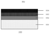
- FIG. 1 shows an embodiment of the present invention. At least a part of the material to be processed 101 has a carbon concentration higher than that of the material to be processed and 1.0 wt.
- the steel member 100 is formed by sequentially laminating the first layer 102 and the second layer 103, which are high-carbon steel layers that are not more than%.
- the carbon concentration of the second layer is set higher than that of the first layer.
- the carbon concentration is higher than that of the second layer and the carbon concentration is 1.0 wt.
- the third layer 104 which is not more than% is stacked.
- Examples of materials to be surface treated include low carbon steel and low carbon alloy steel.
- Examples include highly tough materials such as chrome steel, chrome molybdenum steel, chrome molybdenum nickel steel, chrome manganese steel, and chrome nickel steel (stainless steel).
- Each alloy composition is based on various standards such as JIS and ASTM. Stipulated in
- the plurality of high carbon steel layers coated on the material to be treated all have a carbon concentration higher than that of the material to be treated and 1.0 wt. % Or less is required. It can be set as the layer excellent in fatigue strength by making carbon concentration of each layer higher than a processed material. Further, the carbon concentration of each layer is set to 1.0 wt. By setting the ratio to not more than%, it is possible to prevent excessive precipitation of reticulated cementite at the grain boundaries, so that surface embrittlement can be reduced and a layer having a long fatigue life can be obtained.
- the high carbon steel layer includes at least a first layer and a second layer, and if necessary, further forms one or more layers thereon, and the carbon concentration increases from the material to be processed toward the outermost surface layer. ing.
- the difference in carbon concentration between the layers can be reduced by providing multiple layers. Peeling between steel layers, peeling between high carbon steel layers, cracks, and the like can be reduced. Furthermore, the required carbon concentration and layer thickness can be freely adjusted. When the number of layers is three or more, even if there is a large difference in carbon concentration between the outermost surface layer and the material to be processed, the difference in carbon concentration between the layers can be reduced. Further, peeling between layers can be reduced.
- alloy composition other than carbon in each layer examples include high carbon steel and high carbon alloy steel.
- the first layer, the second layer, and the one or more layers formed as necessary (hereinafter referred to as a plurality of high carbon steel layers) in which the composition of alloy elements other than carbon substantially matches the material to be treated It is suitable because it is excellent in integrity with the object to be processed and can prevent the generation of local composite compounds. In addition to fatigue resistance, other properties such as corrosion resistance and heat resistance are improved at the same time. It is possible to adjust other alloy elements to achieve this.
- the plurality of high carbon steel layers may be formed with the same thickness on the entire surface of the material to be processed, but each layer has a thickness distribution on the surface of the material to be processed, or a part of the material to be processed. It can also be formed in a limited manner. For example, in the case of mechanical parts, if the shaft is a contact part with a bearing, if it is a gear, it is a tooth tip, and if it is a press roll, it is a part that requires particularly high fatigue strength, such as a contact part with a member. Each layer can be formed in a limited manner. Such a partial process is suitable when individually controlling the characteristics of a location where toughness is desired and a location where fatigue resistance is desired.
- a distribution is given on the surface of the material to be treated, such as a place where no layer is formed, a place where only the first layer is formed, a place where the first layer and the second layer are formed. It is also possible to form each layer. Similarly, one or more layers formed on the second layer can be partially formed on the material to be processed.
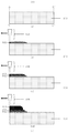
- Examples of methods that are excellent in forming speed and adhesion to a material to be processed include a cold spray method, a warm spray method, a plasma spray method, an arc method, and the like. Examples include a thermal spraying method, a flame spraying method, a build-up welding method, and an aerosol deposition method, and a method of sequentially forming each layer as shown in FIG.
- a material 101 to be processed on which a high carbon steel layer is formed is prepared.
- the first layer 102 is formed on the workpiece 101.
- the material of each layer is supplied in the form of powder, wire, bar, etc. so as to suit each method.
- a method of spraying powder and depositing it on the material to be processed is used.
- the film is formed by the above method using a powder having a low carbon concentration (first powder).
- the carbon concentration of this powder is higher than that of the material to be treated, and is 1.0 wt. % Or less.
- the first powder may be a mixture of carbon and another powder.
- the second layer 102 is formed on the first layer 102.
- the second layer is formed on the first layer 102 using a powder (second powder) having a higher carbon concentration than the first layer.
- the second powder may be a mixture of carbon and other powders as in the first split.
- the concentration of carbon contained in the entire layer is higher than that of the first layer, and 1.0 wt. % Or less.
- the type of raw material necessary for layer formation can be reduced even when the high carbon steel layer is a multilayer.
- the film formation conditions are appropriately adjusted according to the method used, the material to be processed, and the material of each layer. However, when the temperature of the material to be processed at the time of film formation is room temperature or higher, the film formation efficiency is improved, and the material to be processed for each layer This is suitable because it can increase the adhesion to the substrate and promote interdiffusion at the interface of each layer. However, it is desirable to adjust the film formation temperature according to various conditions such as the heat resistance and oxidation resistance of the material to be processed and the material of each layer. In addition to the formation of the above layers, it is possible to further perform heat treatment such as quenching and tempering, and surface treatment such as carburizing and nitriding.
- FIG. 1 The block diagram of the steel member 100 in a present Example is as FIG.
- stainless steel JIS standard: SUS304, manufactured by Nisshin Steel Co., Ltd., 0.05 wt.% Having a length of 50 mm, a width of 50 mm, and a thickness of 10 mm was used as the material 101 to be processed for the steel member 100.
- the first layer 102 and the second layer 103 are made of stainless steel powder (DAP304L, manufactured by Daido Special Steel) as a raw material, and additive-free stainless steel powder A and 2.0 wt.
- the two powders of the supported stainless steel powder B were mixed at a specified weight ratio to obtain respective raw material powders.
- FIG. 1 is a schematic diagram for easily distinguishing each layer, and the actual film thickness is as shown in Table 1 shown later. Theoretically, the carbon concentration at the time of powder adjustment matches the carbon concentration of the layer after film formation. Slightly lower value.
- the formation method of the first layer and the second layer in the present embodiment is as shown in FIG.
- the first layer and the second layer are formed using a cold spray method, using nitrogen gas as a carrier gas, a pressure of 4 MPa, a material temperature of 400 ° C., and a nozzle distance of 20 mm. Formed. When the material to be treated is heated, the powder easily adheres, and the adhesion between the layers is further improved. Thereafter, the raw material powder was changed to form a second layer by the cold spray method under the same conditions. And in order to make the graphite powder carry
- the carbon concentration of the first layer is 0.8 wt. % Was formed by the cold spray method, and the second layer was not formed.
- Other formation conditions are the same as those in the first embodiment.
- Example 1 a surface treatment layer having a thickness of about 1 mm and a Vickers hardness (Hv) of 920 on the surface of the steel member 100 and having excellent adhesion without delamination even after the Falex test was obtained.
- Hv Vickers hardness
- Comparative Example 1 minute peeling was observed between the material to be processed 101 and the first layer 102, and a problem occurred in adhesion.
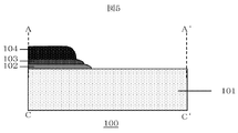
- the schematic diagram of the steel member 100 in the present embodiment is as shown in FIG.
- a workpiece 101 made of chromium molybdenum steel JIS standard: SCM415, manufactured by Daido Steel Co., Ltd., 0.15 wt.% Having a diameter of 30 mm and a length of 300 mm was used.
- a first layer 102, a second layer 103, and a third layer 104 were formed on the tip of the material to be processed.
- FIG. 5 shows a schematic cross-sectional view of A-A ′ attached to FIG.
- the sectional view shows up to C-C '.
- the first layer 102, the second layer 103, and the third layer 104 are formed at the tip of the workpiece 101, and all three layers are 100 mm from the tip, and all the three layers are 100 mm to 110 mm. Only the first layer 101 was formed in the first layer 101 and the second layer 102 in the range of 110 mm to 120 mm.
- FIG. 4 is a schematic diagram for making it easy to distinguish each layer, and the actual film thickness is as shown in Table 2 shown later.
- Each of these layers is composed of chromium molybdenum steel powder A made of chrome molybdenum steel powder (SCM415, Epson Atmix) of the same standard as the material to be treated 101, and only the carbon concentration of chromium molybdenum steel powder A is 2.0 wt.
- Each raw material powder was obtained by mixing two kinds of powders of chrome molybdenum steel powder B increased to% by a specified weight ratio.
- the formation method of the first layer, the second layer, and the third layer in this example is as shown in FIG.
- Plasma spraying was used to form each layer.
- the raw material powder was changed in the order of the first layer, the second layer, and the third layer, and the film was formed under the same conditions.
- the spray nozzle 106 is scanned over the material 101 while rotating the material 101 preheated to 400 ° C., and the desired part is partially formed as shown in FIG. Each layer was formed.
- the other formation conditions are the same as those in Example 2.
- the second layer and the third layer were not formed.
- the other formation conditions are the same as those in Example 2.
- the other formation conditions are the same as those in Example 2.
- the steel member 100 obtained in Examples 2 and 3 and Comparative Examples 2 and 3 was smoothed by mechanical polishing and buffing so that the surface roughness (Ra) was 1.0 ⁇ m or less, and then the third layer.
- a Falex test according to ASTM-D-3233 was conducted in the lubricating oil on the film forming portion 103.
- the steel member 100 after the Falex test was cut, the thickness of each layer, the average carbon concentration measured with an electron beam microanalyzer (Shimadzu Corporation), the presence or absence of delamination confirmed with an optical microscope, and the surface roughness of the outermost layer ( Table 2 shows the cross-sectional Vickers hardness measured with a Ra), micro Vickers hardness tester (Shimadzu Corporation).
- the steel member having the configuration disclosed in the present invention has a surface treatment layer having excellent surface hardness and adhesion to the material to be treated.
- a shaft as a machine part is shown.
- the present invention can be applied to various machine parts such as a drive part, a gear, and a bearing.
Landscapes
- Chemical & Material Sciences (AREA)
- Engineering & Computer Science (AREA)
- Chemical Kinetics & Catalysis (AREA)
- Materials Engineering (AREA)
- Mechanical Engineering (AREA)
- Metallurgy (AREA)
- Organic Chemistry (AREA)
- Physics & Mathematics (AREA)
- Plasma & Fusion (AREA)
- Inorganic Chemistry (AREA)
- Other Surface Treatments For Metallic Materials (AREA)
- Coating By Spraying Or Casting (AREA)
Abstract
Priority Applications (5)
| Application Number | Priority Date | Filing Date | Title |
|---|---|---|---|
| US14/897,113 US20160138151A1 (en) | 2013-06-10 | 2013-06-10 | Steel Part and Method for Manufacturing the Same |
| JP2015522272A JP6062048B2 (ja) | 2013-06-10 | 2013-06-10 | 鉄鋼部材および鉄鋼部材の製造方法 |
| PCT/JP2013/065916 WO2014199423A1 (fr) | 2013-06-10 | 2013-06-10 | Élément d'acier et procédé de production d'élément d'acier |
| AU2013392321A AU2013392321B2 (en) | 2013-06-10 | 2013-06-10 | Steel part and method for manufacturing the same |
| CN201380077305.6A CN105308213A (zh) | 2013-06-10 | 2013-06-10 | 钢铁部件和钢铁部件的制造方法 |
Applications Claiming Priority (1)
| Application Number | Priority Date | Filing Date | Title |
|---|---|---|---|
| PCT/JP2013/065916 WO2014199423A1 (fr) | 2013-06-10 | 2013-06-10 | Élément d'acier et procédé de production d'élément d'acier |
Publications (1)
| Publication Number | Publication Date |
|---|---|
| WO2014199423A1 true WO2014199423A1 (fr) | 2014-12-18 |
Family
ID=52021759
Family Applications (1)
| Application Number | Title | Priority Date | Filing Date |
|---|---|---|---|
| PCT/JP2013/065916 Ceased WO2014199423A1 (fr) | 2013-06-10 | 2013-06-10 | Élément d'acier et procédé de production d'élément d'acier |
Country Status (5)
| Country | Link |
|---|---|
| US (1) | US20160138151A1 (fr) |
| JP (1) | JP6062048B2 (fr) |
| CN (1) | CN105308213A (fr) |
| AU (1) | AU2013392321B2 (fr) |
| WO (1) | WO2014199423A1 (fr) |
Families Citing this family (5)
| Publication number | Priority date | Publication date | Assignee | Title |
|---|---|---|---|---|
| DE102018203637A1 (de) | 2018-03-09 | 2019-09-12 | Volkswagen Aktiengesellschaft | Gestaltung des Übergangs von Laserauftragsschweißgut zu Substrat zur Verminderung der Kerbwirkung |
| US12116688B2 (en) * | 2019-12-20 | 2024-10-15 | Nippon Steel Corporation | Ni-plated steel sheet, and method for manufacturing Ni-plated steel sheet |
| GB202004947D0 (en) * | 2020-04-03 | 2020-05-20 | Rolls Royce Plc | Joining component bodies |
| EP3933067A1 (fr) * | 2020-07-03 | 2022-01-05 | Flender GmbH | Procédé de fabrication d'un revêtement, revêtement, composant doté d'un revêtement |
| CN113957434B (zh) * | 2021-10-22 | 2022-11-04 | 燕山大学 | 一种在低碳钢表面制备高硬度高耐磨熔覆层的方法 |
Citations (3)
| Publication number | Priority date | Publication date | Assignee | Title |
|---|---|---|---|---|
| JP2002503293A (ja) * | 1998-04-08 | 2002-01-29 | キャタピラー インコーポレイテッド | 性能改善のため部品に機能勾配材料コーティングを形成する方法 |
| JP2009537334A (ja) * | 2006-05-19 | 2009-10-29 | シエフレル・コマンデイトゲゼルシヤフト | 転がり軸受部材の製造方法及び転がり軸受部材 |
| JP2012077339A (ja) * | 2010-09-30 | 2012-04-19 | Tohoku Univ | コールドスプレー法による金属材料の補修方法及びコールドスプレー用粉末材料の製造方法、並びに、コールドスプレー皮膜 |
Family Cites Families (1)
| Publication number | Priority date | Publication date | Assignee | Title |
|---|---|---|---|---|
| DE3315556C1 (de) * | 1983-04-29 | 1984-11-29 | Goetze Ag, 5093 Burscheid | Verschleissfeste Beschichtung |
-
2013
- 2013-06-10 CN CN201380077305.6A patent/CN105308213A/zh active Pending
- 2013-06-10 AU AU2013392321A patent/AU2013392321B2/en not_active Ceased
- 2013-06-10 US US14/897,113 patent/US20160138151A1/en not_active Abandoned
- 2013-06-10 WO PCT/JP2013/065916 patent/WO2014199423A1/fr not_active Ceased
- 2013-06-10 JP JP2015522272A patent/JP6062048B2/ja not_active Expired - Fee Related
Patent Citations (3)
| Publication number | Priority date | Publication date | Assignee | Title |
|---|---|---|---|---|
| JP2002503293A (ja) * | 1998-04-08 | 2002-01-29 | キャタピラー インコーポレイテッド | 性能改善のため部品に機能勾配材料コーティングを形成する方法 |
| JP2009537334A (ja) * | 2006-05-19 | 2009-10-29 | シエフレル・コマンデイトゲゼルシヤフト | 転がり軸受部材の製造方法及び転がり軸受部材 |
| JP2012077339A (ja) * | 2010-09-30 | 2012-04-19 | Tohoku Univ | コールドスプレー法による金属材料の補修方法及びコールドスプレー用粉末材料の製造方法、並びに、コールドスプレー皮膜 |
Also Published As
| Publication number | Publication date |
|---|---|
| US20160138151A1 (en) | 2016-05-19 |
| AU2013392321B2 (en) | 2016-09-29 |
| AU2013392321A1 (en) | 2016-01-07 |
| CN105308213A (zh) | 2016-02-03 |
| JP6062048B2 (ja) | 2017-01-18 |
| JPWO2014199423A1 (ja) | 2017-02-23 |
Similar Documents
| Publication | Publication Date | Title |
|---|---|---|
| JP6062048B2 (ja) | 鉄鋼部材および鉄鋼部材の製造方法 | |
| KR102545083B1 (ko) | 분말 층 융합용 3d 인쇄 가능한 경질 철계 금속 합금 | |
| JP5669390B2 (ja) | 耐摩耗性コーティングならびにこのための製造法 | |
| CN105917030B (zh) | 用于生成含有铬的多层涂层的方法和涂覆的物体 | |
| EP2679701B1 (fr) | Procédé pour la fabrication d' un élément en acier nitruré | |
| JP5920681B2 (ja) | 摺動特性に優れた塑性加工用被覆金型及びその製造方法 | |
| US20170122392A1 (en) | Brake Disc for a Motor Vehicle | |
| JP6539825B2 (ja) | 工具材の製造方法及び工具 | |
| WO2011013559A1 (fr) | Procédé de traitement thermique combiné et élément d'acier trempé | |
| JP3861097B2 (ja) | 回転機械 | |
| US20120028031A1 (en) | Iron-based sintered material | |
| US8852751B2 (en) | Wear resistant device and process therefor | |
| JPWO2011151929A1 (ja) | 熱間圧延設備用ロールおよびその製造方法 | |
| US12263513B2 (en) | Coated die for use in hot stamping | |
| US9556531B2 (en) | Method for ultra-fast boriding | |
| JP2014087858A (ja) | 切削工具 | |
| JP2008150650A (ja) | 鋼系複合表面処理製品とその製造方法 | |
| JP2016211052A (ja) | 硬質皮膜および硬質皮膜被覆部材 | |
| JP2011147946A (ja) | 温熱間鍛造用金型及びその製造方法 | |
| US11434976B2 (en) | Layer of hard material on a metal substrate | |
| CN117418188B (zh) | 一种空间多层润滑膜及其制备方法 | |
| JP2007046103A (ja) | 硬質皮膜 | |
| EP4200533B1 (fr) | Élément d'un palier lisse | |
| JP2019060002A (ja) | 焼却炉用熱電対の保護管用構造体及びその製造方法 | |
| JP2010168638A (ja) | 硬質皮膜被覆部材および成形用治工具 |
Legal Events
| Date | Code | Title | Description |
|---|---|---|---|
| WWE | Wipo information: entry into national phase |
Ref document number: 201380077305.6 Country of ref document: CN |
|
| 121 | Ep: the epo has been informed by wipo that ep was designated in this application |
Ref document number: 13886926 Country of ref document: EP Kind code of ref document: A1 |
|
| ENP | Entry into the national phase |
Ref document number: 2015522272 Country of ref document: JP Kind code of ref document: A |
|
| WWE | Wipo information: entry into national phase |
Ref document number: 14897113 Country of ref document: US |
|
| NENP | Non-entry into the national phase |
Ref country code: DE |
|
| ENP | Entry into the national phase |
Ref document number: 2013392321 Country of ref document: AU Date of ref document: 20130610 Kind code of ref document: A |
|
| 122 | Ep: pct application non-entry in european phase |
Ref document number: 13886926 Country of ref document: EP Kind code of ref document: A1 |