WO2014199431A1 - Dispositif de transmission entre véhicules - Google Patents
Dispositif de transmission entre véhicules Download PDFInfo
- Publication number
- WO2014199431A1 WO2014199431A1 PCT/JP2013/065987 JP2013065987W WO2014199431A1 WO 2014199431 A1 WO2014199431 A1 WO 2014199431A1 JP 2013065987 W JP2013065987 W JP 2013065987W WO 2014199431 A1 WO2014199431 A1 WO 2014199431A1
- Authority
- WO
- WIPO (PCT)
- Prior art keywords
- vehicle
- voltage
- electrical contact
- inter
- communication control
- Prior art date
- Legal status (The legal status is an assumption and is not a legal conclusion. Google has not performed a legal analysis and makes no representation as to the accuracy of the status listed.)
- Ceased
Links
Images

Classifications
-
- H—ELECTRICITY
- H04—ELECTRIC COMMUNICATION TECHNIQUE
- H04B—TRANSMISSION
- H04B1/00—Details of transmission systems, not covered by a single one of groups H04B3/00 - H04B13/00; Details of transmission systems not characterised by the medium used for transmission
- H04B1/38—Transceivers, i.e. devices in which transmitter and receiver form a structural unit and in which at least one part is used for functions of transmitting and receiving
- H04B1/3822—Transceivers, i.e. devices in which transmitter and receiver form a structural unit and in which at least one part is used for functions of transmitting and receiving specially adapted for use in vehicles
-
- B—PERFORMING OPERATIONS; TRANSPORTING
- B60—VEHICLES IN GENERAL
- B60L—PROPULSION OF ELECTRICALLY-PROPELLED VEHICLES; SUPPLYING ELECTRIC POWER FOR AUXILIARY EQUIPMENT OF ELECTRICALLY-PROPELLED VEHICLES; ELECTRODYNAMIC BRAKE SYSTEMS FOR VEHICLES IN GENERAL; MAGNETIC SUSPENSION OR LEVITATION FOR VEHICLES; MONITORING OPERATING VARIABLES OF ELECTRICALLY-PROPELLED VEHICLES; ELECTRIC SAFETY DEVICES FOR ELECTRICALLY-PROPELLED VEHICLES
- B60L15/00—Methods, circuits, or devices for controlling the traction-motor speed of electrically-propelled vehicles
- B60L15/42—Adaptation of control equipment on vehicle for actuation from alternative parts of the vehicle or from alternative vehicles of the same vehicle train
-
- B—PERFORMING OPERATIONS; TRANSPORTING
- B61—RAILWAYS
- B61L—GUIDING RAILWAY TRAFFIC; ENSURING THE SAFETY OF RAILWAY TRAFFIC
- B61L15/00—Indicators provided on the vehicle or train for signalling purposes
- B61L15/0018—Communication with or on the vehicle or train
- B61L15/0036—Conductor-based, e.g. using CAN-Bus, train-line or optical fibres
-
- H—ELECTRICITY
- H04—ELECTRIC COMMUNICATION TECHNIQUE
- H04B—TRANSMISSION
- H04B3/00—Line transmission systems
- H04B3/54—Systems for transmission via power distribution lines
- H04B3/548—Systems for transmission via power distribution lines the power on the line being DC
-
- B—PERFORMING OPERATIONS; TRANSPORTING
- B60—VEHICLES IN GENERAL
- B60L—PROPULSION OF ELECTRICALLY-PROPELLED VEHICLES; SUPPLYING ELECTRIC POWER FOR AUXILIARY EQUIPMENT OF ELECTRICALLY-PROPELLED VEHICLES; ELECTRODYNAMIC BRAKE SYSTEMS FOR VEHICLES IN GENERAL; MAGNETIC SUSPENSION OR LEVITATION FOR VEHICLES; MONITORING OPERATING VARIABLES OF ELECTRICALLY-PROPELLED VEHICLES; ELECTRIC SAFETY DEVICES FOR ELECTRICALLY-PROPELLED VEHICLES
- B60L2200/00—Type of vehicles
- B60L2200/26—Rail vehicles
-
- H—ELECTRICITY
- H04—ELECTRIC COMMUNICATION TECHNIQUE
- H04B—TRANSMISSION
- H04B2203/00—Indexing scheme relating to line transmission systems
- H04B2203/54—Aspects of powerline communications not already covered by H04B3/54 and its subgroups
- H04B2203/5429—Applications for powerline communications
- H04B2203/5445—Local network
-
- H—ELECTRICITY
- H04—ELECTRIC COMMUNICATION TECHNIQUE
- H04B—TRANSMISSION
- H04B2203/00—Indexing scheme relating to line transmission systems
- H04B2203/54—Aspects of powerline communications not already covered by H04B3/54 and its subgroups
- H04B2203/5462—Systems for power line communications
- H04B2203/547—Systems for power line communications via DC power distribution
-
- H—ELECTRICITY
- H04—ELECTRIC COMMUNICATION TECHNIQUE
- H04L—TRANSMISSION OF DIGITAL INFORMATION, e.g. TELEGRAPHIC COMMUNICATION
- H04L12/00—Data switching networks
- H04L12/28—Data switching networks characterised by path configuration, e.g. LAN [Local Area Networks] or WAN [Wide Area Networks]
- H04L12/40—Bus networks
- H04L2012/40267—Bus for use in transportation systems
- H04L2012/40293—Bus for use in transportation systems the transportation system being a train
-
- Y—GENERAL TAGGING OF NEW TECHNOLOGICAL DEVELOPMENTS; GENERAL TAGGING OF CROSS-SECTIONAL TECHNOLOGIES SPANNING OVER SEVERAL SECTIONS OF THE IPC; TECHNICAL SUBJECTS COVERED BY FORMER USPC CROSS-REFERENCE ART COLLECTIONS [XRACs] AND DIGESTS
- Y02—TECHNOLOGIES OR APPLICATIONS FOR MITIGATION OR ADAPTATION AGAINST CLIMATE CHANGE
- Y02T—CLIMATE CHANGE MITIGATION TECHNOLOGIES RELATED TO TRANSPORTATION
- Y02T90/00—Enabling technologies or technologies with a potential or indirect contribution to GHG emissions mitigation
- Y02T90/10—Technologies relating to charging of electric vehicles
- Y02T90/16—Information or communication technologies improving the operation of electric vehicles
Definitions
- the present invention relates to an inter-vehicle transmission device that transmits signals to and from other vehicles.
- Patent Document 1 discloses a technique for destroying an oxide film by applying a direct current component to a contact portion of a connector.
- a DC component is pressurized against the connector by connecting a DC voltage source between the transformer and the connector.
- the present invention has been made in view of the above, and an object of the present invention is to obtain an inter-vehicle transmission device capable of destroying an oxide film of an electric coupler while suppressing a decrease in signal quality.
- the present invention provides a vehicle including an electrical coupler that establishes a communication path with the other vehicle by using an electrical contact portion with the other vehicle.
- a vehicle-to-vehicle transmission apparatus comprising: a communication control means for controlling communication with the other vehicle; a pulse transformer disposed between the communication control means and the electrical coupler; and a midpoint of the pulse transformer And a power supply device that pressurizes a DC voltage to the electrical contact portion between the electrical coupler and the electrical coupler of the other vehicle.
- the inter-vehicle transmission device has an effect that the oxide film of the electrical coupler can be destroyed while suppressing a decrease in signal quality.
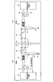
- FIG. 1 is a diagram illustrating a configuration example of an inter-vehicle communication system according to the first embodiment.
- FIG. 2 is a diagram illustrating a configuration example of an inter-vehicle communication system according to the second embodiment.
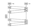
- FIG. 3 is a diagram illustrating a time for applying a DC voltage to the electrical contact portion.
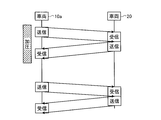
- FIG. 4 is a diagram illustrating a time for applying a DC voltage to the electrical contact portion.
- FIG. 1 is a diagram illustrating a configuration example of an inter-vehicle communication system according to the present embodiment.
- the inter-vehicle communication system includes a vehicle 10 and a vehicle 20.
- the vehicle 10 pressurizes a DC voltage at the electrical contact portion of the electrical coupler between the vehicle 10 and the vehicle 20.
- the vehicle 10 includes a communication control circuit 11, a transmission circuit 12, a reception circuit 13, a pulse transformer 14, a shielded twisted pair cable 15, an electrical coupler 16, a power supply device 17, and a capacitor as an inter-vehicle transmission device. 18.
- the communication control circuit 11 is communication control means for controlling communication with the vehicle 20 side.
- the transmission circuit 12 is a transmission unit that transmits a signal to the vehicle 20 side.
- the receiving circuit 13 is a receiving unit that receives a signal from the vehicle 20 side.
- the pulse transformer 14 is disposed between the communication control circuit 11, the transmission circuit 12, the reception circuit 13 side and the electrical coupler 16 side, and insulates the circuit on the signal transmission / reception side from the electrical coupler 16 side in a DC manner.
- the shielded twisted pair cable 15 is a communication path from the pulse transformer 14 to the electrical coupler 16.
- the electrical coupler 16 is a connection portion with the vehicle 20 side, and constructs a communication path with the vehicle 20 by using an electrical contact portion with the electrical coupler of the vehicle 20.
- the power supply device 17 is disposed between the middle point of the pulse transformer 14 and the electrical coupler 16 and pressurizes a DC voltage at the electrical contact portion.
- the capacitor 18 insulates the vehicle body side of the vehicle 10 from
- the vehicle 20 includes a communication control circuit 21, a transmission circuit 22, a reception circuit 23, a pulse transformer 24, a shielded twisted pair cable 25, an electrical coupler 26, a load resistor 27, and an inter-vehicle transmission device. And a capacitor 28.
- the communication control circuit 21 is communication control means for controlling communication with the vehicle 10 side.
- the transmission circuit 22 is a transmission unit that transmits a signal to the vehicle 10 side.
- the receiving circuit 23 is a receiving unit that receives a signal from the vehicle 10 side.
- the pulse transformer 24 is disposed between the communication control circuit 21, the transmission circuit 22, the reception circuit 23 side and the electrical coupler 26 side, and insulates the circuit on the signal transmission / reception side from the electrical coupler 26 side in a DC manner.
- the shielded twisted pair cable 25 is a communication path from the pulse transformer 24 to the electrical coupler 26.
- the electrical coupler 26 is a connection portion with the vehicle 10 side, and constructs a communication path with the vehicle 10 by using an electrical contact portion with the electrical coupler 16 of the vehicle 10.
- the load resistor 27 is a resistor disposed between the middle point of the pulse transformer 24 and the electrical coupler 26.
- the capacitor 28 insulates the vehicle body side of the vehicle 20 from the signal path in a DC manner.
- the power supply device 17 is connected to a load resistor 27 via the electrical coupler 16 of the vehicle 10 and the electrical coupler 26 of the vehicle 20.
- the power supply device 17 pressurizes a DC voltage at the electrical contact portion between the electrical coupler 16 and the electrical coupler 26, so that an oxide film is formed when the electrical couplers 16 and 26 have an oxide film. Can be destroyed.
- the power supply device 17 is disposed at a position insulated from the vehicle body side of the vehicle 10.
- the path from the power supply device 17 to the electrical coupler 16 is a shield portion of the shielded twisted pair cable 15.
- the power supply device 17 does not have to be equipped with a dedicated battery.
- a battery for example, 100V mounted on the vehicle 10, or a 24V voltage converted from the battery (100V) can be used.
- a DC voltage is applied to the electrical contact portion between the electrical coupler 16 of the vehicle 10 and the electrical coupler 26 of the vehicle 20.
- the power supply device 17 for pressing is arranged between the middle point of the pulse transformer 14 and the electric coupler 16.
- Embodiment 2 FIG.
- the power supply device 17 constantly pressurizes a DC voltage at the electrical contact portion. Since the power supply device 17 continues to pressurize the DC voltage even after the oxide film is destroyed, the power is wasted. In the present embodiment, the oxide film is destroyed without wasting power. A different part from Embodiment 1 is demonstrated.
- FIG. 2 is a diagram illustrating a configuration example of the inter-vehicle communication system according to the present embodiment.
- the inter-vehicle communication system includes a vehicle 10 a and a vehicle 20.
- the vehicle 10a performs control to pressurize a DC voltage at the electrical contact portion of the electrical coupler between the vehicle 10a and the vehicle 20.
- vehicle 10a performs control to pressurize a DC voltage at the electrical contact portion of the electrical coupler between the vehicle 10a and the vehicle 20.
- both vehicles vehicle (vehicles 10a and 20) perform control to pressurize the DC voltage. You may make it perform.
- the vehicle 10a includes a communication control circuit 11a, a transmission circuit 12, a reception circuit 13, a pulse transformer 14, a shielded twisted pair cable 15, an electrical coupler 16, a power supply device 17, and a capacitor as an inter-vehicle transmission device. 18 and a switch 19.
- the communication control circuit 11a is a communication control means for controlling communication with the vehicle 20 side. Moreover, the communication control circuit 11a can operate the switch 19 with a pressurization control signal.
- the switch 19 is disposed between the power supply device 17 and the electrical coupler 16, and switches between connection / disconnection of the power supply device 17 and the electrical coupler 16 under the control of the communication control circuit 11a.
- the communication control circuit 11a of the vehicle 10a transmits a pressurization control signal and operates the switch 19, so that the power supply device 17 is electrically connected between the electrical coupler 16 and the electrical coupler 26. It is possible to control the time for applying the DC voltage to the contact portion.
- the communication control circuit 11a can operate the switch 19 to pressurize a DC voltage to the electrical contact portion when the power supply device 17 and the electrical coupler 16 are connected, and the power supply device 17 and the electrical coupler 16 are disconnected. When this is done, the application of DC voltage to the electrical contact portion can be stopped. That is, the communication control circuit 11 a can pressurize the DC voltage to the electrical contact portion while operating the switch 19 to connect the power supply device 17 and the electrical coupler 16.
- the communication control circuit 11a operates the switch 19 after turning on its own power, pressurizes the DC voltage of the power supply device 17 to the electrical contact portion, and operates the switch 19 after a certain period of time to the electrical contact portion. Stop applying DC voltage.
- the power supply device 17 can destroy the oxide film when the oxide film is generated on the electrical couplers 16 and 26.
- the communication control circuit 11a detects the connection with the vehicle 20, the communication control circuit 11a operates the switch 19 to pressurize the DC voltage of the power supply device 17 to the electrical contact portion, and operates the switch 19 after a certain period of time to operate the electricity. Stops the application of DC voltage to the target contact.
- the power supply device 17 can destroy the oxide film when the oxide film is generated on the electrical couplers 16 and 26.
- the communication control circuit 11a when the communication control circuit 11a detects a transmission failure in communication with the vehicle 20, the communication control circuit 11a operates the switch 19 to pressurize the DC voltage of the power supply device 17 to the electrical contact portion, and the switch 19 To stop applying DC voltage to the electrical contacts.
- the power supply device 17 can destroy the oxide film when the oxide film is generated on the electrical couplers 16 and 26.
- the transmission circuit 12 of the vehicle 10a transmits a signal and the reception circuit 23 of the vehicle 20 receives the signal.
- the switch 19 is operated to pressurize the DC voltage of the power supply device 17 to the electrical contact portion, and a certain time has elapsed. Thereafter, the switch 19 is operated to stop the pressurization of the DC voltage on the electrical contact portion every predetermined number of cycles.
- the power supply device 17 can destroy the oxide film when the oxide film is generated on the electrical couplers 16 and 26.
- the transmission circuit 12 of the vehicle 10a transmits a signal
- the reception circuit 23 of the vehicle 20 receives the signal
- the transmission circuit 22 of the vehicle 20 transmits a signal to transmit the signal of the vehicle 10a.
- the communication control circuit 11a operates the switch 19 so that the vehicle 10a does not start the next signal transmission after the vehicle 10a completes signal reception.
- the DC voltage of the power supply device 17 can be pressurized to the electrical contact portion.
- FIG. 3 is a diagram showing the time for applying the DC voltage of the power supply device to the electrical contact portion.
- the communication control circuit 11a pressurizes the DC voltage of the power supply device 17 at the electrical contact portion during the time between the previous communication and the next communication.
- the transmission circuit 12 of the vehicle 10a transmits a signal and the reception circuit 23 of the vehicle 20 receives the signal, and the transmission circuit 22 of the vehicle 20 transmits the signal and transmits the signal of the vehicle 10a.
- the communication control circuit 11a operates the switch 19 until the vehicle 10a completes signal reception from the start of signal transmission of the vehicle 10a.
- the DC voltage of the power supply device 17 can be applied to the electrical contact portion.
- the communication control circuit 11a detects a transmission failure with the vehicle 20 in the communication with the DC voltage applied to the electrical contact portion, the communication control circuit 11a continues to apply the DC voltage to the electrical contact portion. be able to.
- FIG. 4 is a diagram showing the time for pressurizing the DC voltage of the power supply device to the electrical contact portion.
- the communication control circuit 11a pressurizes the DC voltage of the power supply device 17 to the electrical contact portion during the time during which each communication is being executed.
- the timing of pressurizing and stopping the pressurization of the DC voltage of the power supply device 17 at the electrical contact portion does not depend on the time zone in which the vehicles 10a and 20 transmit and receive, respectively. To do.
- the communication control circuit 11a can perform control based on a timer (not shown) provided in the host vehicle, the communication control circuit 11a can be executed with simple control.
- the communication control circuit 11a operates the switch 19 to supply power to the electrical contact portion between the electrical coupler 16 of the vehicle 10a and the electrical coupler 26 of the vehicle 20.
- the communication control circuit 11a may pressurize the DC voltage at a timing such as when the connection with the vehicle 20 is detected after the power is turned on, or when a transmission failure is detected through communication with the vehicle 20. it can.
- the oxide film can be destroyed without wasting power.
Landscapes
- Engineering & Computer Science (AREA)
- Power Engineering (AREA)
- Mechanical Engineering (AREA)
- Computer Networks & Wireless Communication (AREA)
- Signal Processing (AREA)
- Transportation (AREA)
- Cable Transmission Systems, Equalization Of Radio And Reduction Of Echo (AREA)
- Electric Propulsion And Braking For Vehicles (AREA)
- Keying Circuit Devices (AREA)
- Dc Digital Transmission (AREA)
Abstract
Priority Applications (6)
| Application Number | Priority Date | Filing Date | Title |
|---|---|---|---|
| US14/896,712 US9838057B2 (en) | 2013-06-10 | 2013-06-10 | Inter-vehicle communication device |
| JP2015522280A JP5893220B2 (ja) | 2013-06-10 | 2013-06-10 | 車両間伝送装置 |
| PCT/JP2013/065987 WO2014199431A1 (fr) | 2013-06-10 | 2013-06-10 | Dispositif de transmission entre véhicules |
| CN201380077176.0A CN105264730B (zh) | 2013-06-10 | 2013-06-10 | 车辆间传输装置 |
| EP13886927.6A EP3010103B1 (fr) | 2013-06-10 | 2013-06-10 | Dispositif de transmission entre véhicules |
| TW102141216A TWI531177B (zh) | 2013-06-10 | 2013-11-13 | 車輛間傳送裝置 |
Applications Claiming Priority (1)
| Application Number | Priority Date | Filing Date | Title |
|---|---|---|---|
| PCT/JP2013/065987 WO2014199431A1 (fr) | 2013-06-10 | 2013-06-10 | Dispositif de transmission entre véhicules |
Publications (1)
| Publication Number | Publication Date |
|---|---|
| WO2014199431A1 true WO2014199431A1 (fr) | 2014-12-18 |
Family
ID=52021767
Family Applications (1)
| Application Number | Title | Priority Date | Filing Date |
|---|---|---|---|
| PCT/JP2013/065987 Ceased WO2014199431A1 (fr) | 2013-06-10 | 2013-06-10 | Dispositif de transmission entre véhicules |
Country Status (6)
| Country | Link |
|---|---|
| US (1) | US9838057B2 (fr) |
| EP (1) | EP3010103B1 (fr) |
| JP (1) | JP5893220B2 (fr) |
| CN (1) | CN105264730B (fr) |
| TW (1) | TWI531177B (fr) |
| WO (1) | WO2014199431A1 (fr) |
Cited By (5)
| Publication number | Priority date | Publication date | Assignee | Title |
|---|---|---|---|---|
| JP2017152900A (ja) * | 2016-02-24 | 2017-08-31 | 三菱電機株式会社 | 通信機器 |
| JP6289769B1 (ja) * | 2016-10-24 | 2018-03-07 | 三菱電機株式会社 | 車両間伝送システムおよび伝送装置 |
| JP6297236B1 (ja) * | 2016-10-24 | 2018-03-20 | 三菱電機株式会社 | 車両間伝送システムおよび伝送装置 |
| CN107852194A (zh) * | 2015-07-21 | 2018-03-27 | 三菱电机株式会社 | 车辆间传输装置 |
| JP2019054386A (ja) * | 2017-09-14 | 2019-04-04 | 株式会社加藤製作所 | 伝送ユニット及び建設機械 |
Families Citing this family (1)
| Publication number | Priority date | Publication date | Assignee | Title |
|---|---|---|---|---|
| JP7559663B2 (ja) * | 2021-04-14 | 2024-10-02 | 株式会社デンソー | 車載通信システム,車載用装置及びインターフェイス装置 |
Citations (6)
| Publication number | Priority date | Publication date | Assignee | Title |
|---|---|---|---|---|
| JPH0271621A (ja) | 1988-09-06 | 1990-03-12 | Toshiba Corp | 信号伝送方式 |
| JPH07294590A (ja) * | 1994-04-25 | 1995-11-10 | Sumitomo Electric Ind Ltd | 活線ケーブルの絶縁監視方法 |
| JP2000193708A (ja) * | 1998-12-28 | 2000-07-14 | Hikari Shoko Kk | 非接地電路の絶縁監視方法と絶縁監視装置 |
| JP2005010030A (ja) * | 2003-06-19 | 2005-01-13 | Hitachi Cable Ltd | 電力ケーブルの絶縁劣化診断方法及び装置 |
| JP2006232203A (ja) * | 2005-02-28 | 2006-09-07 | Toshiba Corp | 鉄道車両用伝送装置 |
| JP2009267943A (ja) * | 2008-04-28 | 2009-11-12 | Toshiba Corp | 鉄道車両用伝送装置及び鉄道車両用伝送システム |
Family Cites Families (7)
| Publication number | Priority date | Publication date | Assignee | Title |
|---|---|---|---|---|
| WO1993009612A1 (fr) * | 1991-10-30 | 1993-05-13 | Raychem Corporation | Systeme d'alarme et de test comportant un circuit de couplage ameliore pour une ligne principale complementaire numerique |
| CN1541468A (zh) | 2001-09-25 | 2004-10-27 | 株式会社日立制作所 | 铁道车辆的信息传输装置 |
| WO2006013638A1 (fr) | 2004-08-04 | 2006-02-09 | Hitachi, Ltd. | Connecteur, processeur d’information, et système de transmission d’information |
| CN101151540B (zh) * | 2005-03-31 | 2010-07-21 | 奥克泰克有限公司 | 微小结构体的探针卡、微小结构体的检查装置以及检查方法 |
| WO2008114777A1 (fr) | 2007-03-20 | 2008-09-25 | Mitsubishi Electric Corporation | Appareil de communication destiné à du matériel roulant |
| WO2009072313A1 (fr) * | 2007-12-06 | 2009-06-11 | Mitsubishi Electric Corporation | Appareil de communication entre véhicules ferroviaires |
| CN102138310A (zh) * | 2008-11-28 | 2011-07-27 | 三菱电机株式会社 | 信号传输装置 |
-
2013
- 2013-06-10 WO PCT/JP2013/065987 patent/WO2014199431A1/fr not_active Ceased
- 2013-06-10 EP EP13886927.6A patent/EP3010103B1/fr active Active
- 2013-06-10 US US14/896,712 patent/US9838057B2/en active Active
- 2013-06-10 CN CN201380077176.0A patent/CN105264730B/zh not_active Expired - Fee Related
- 2013-06-10 JP JP2015522280A patent/JP5893220B2/ja not_active Expired - Fee Related
- 2013-11-13 TW TW102141216A patent/TWI531177B/zh not_active IP Right Cessation
Patent Citations (6)
| Publication number | Priority date | Publication date | Assignee | Title |
|---|---|---|---|---|
| JPH0271621A (ja) | 1988-09-06 | 1990-03-12 | Toshiba Corp | 信号伝送方式 |
| JPH07294590A (ja) * | 1994-04-25 | 1995-11-10 | Sumitomo Electric Ind Ltd | 活線ケーブルの絶縁監視方法 |
| JP2000193708A (ja) * | 1998-12-28 | 2000-07-14 | Hikari Shoko Kk | 非接地電路の絶縁監視方法と絶縁監視装置 |
| JP2005010030A (ja) * | 2003-06-19 | 2005-01-13 | Hitachi Cable Ltd | 電力ケーブルの絶縁劣化診断方法及び装置 |
| JP2006232203A (ja) * | 2005-02-28 | 2006-09-07 | Toshiba Corp | 鉄道車両用伝送装置 |
| JP2009267943A (ja) * | 2008-04-28 | 2009-11-12 | Toshiba Corp | 鉄道車両用伝送装置及び鉄道車両用伝送システム |
Cited By (10)
| Publication number | Priority date | Publication date | Assignee | Title |
|---|---|---|---|---|
| CN107852194A (zh) * | 2015-07-21 | 2018-03-27 | 三菱电机株式会社 | 车辆间传输装置 |
| JP2017152900A (ja) * | 2016-02-24 | 2017-08-31 | 三菱電機株式会社 | 通信機器 |
| JP6289769B1 (ja) * | 2016-10-24 | 2018-03-07 | 三菱電機株式会社 | 車両間伝送システムおよび伝送装置 |
| JP6297236B1 (ja) * | 2016-10-24 | 2018-03-20 | 三菱電機株式会社 | 車両間伝送システムおよび伝送装置 |
| WO2018078696A1 (fr) * | 2016-10-24 | 2018-05-03 | 三菱電機株式会社 | Système de transmission entre véhicules et dispositif de transmission |
| WO2018078697A1 (fr) * | 2016-10-24 | 2018-05-03 | 三菱電機株式会社 | Système de transmission entre véhicules, et dispositif de transmission |
| US11007881B2 (en) | 2016-10-24 | 2021-05-18 | Mitsubishi Electric Corporation | Inter-vehicle transmission system and transmission device |
| US11097622B2 (en) | 2016-10-24 | 2021-08-24 | Mitsubishi Electric Corporation | Inter-vehicle transmission system and transmission device |
| JP2019054386A (ja) * | 2017-09-14 | 2019-04-04 | 株式会社加藤製作所 | 伝送ユニット及び建設機械 |
| JP7195731B2 (ja) | 2017-09-14 | 2022-12-26 | 株式会社加藤製作所 | 伝送ユニット及び建設機械 |
Also Published As
| Publication number | Publication date |
|---|---|
| JPWO2014199431A1 (ja) | 2017-02-23 |
| CN105264730B (zh) | 2018-06-12 |
| JP5893220B2 (ja) | 2016-03-23 |
| TWI531177B (zh) | 2016-04-21 |
| EP3010103B1 (fr) | 2019-10-23 |
| US20160134319A1 (en) | 2016-05-12 |
| US9838057B2 (en) | 2017-12-05 |
| EP3010103A4 (fr) | 2017-03-01 |
| CN105264730A (zh) | 2016-01-20 |
| EP3010103A1 (fr) | 2016-04-20 |
| TW201448499A (zh) | 2014-12-16 |
Similar Documents
| Publication | Publication Date | Title |
|---|---|---|
| JP5893220B2 (ja) | 車両間伝送装置 | |
| WO2020122668A3 (fr) | Appareil de stimulation et procédé de stimulation utilisant ce dernier | |
| RU2016144286A (ru) | Система и способ передачи мощности и данных | |
| JP2011066881A5 (fr) | ||
| SA522431297B1 (ar) | جهاز لنقل القدرة الكهربائية من أو إلى مركبة كهربائية، وطريقة تحكم فيها | |
| JP2017519476A5 (fr) | ||
| CN103688439A (zh) | 充电装置和车辆 | |
| WO2019036644A3 (fr) | Procédé de détection d'état de fonctionnement d'un relais de verrouillage de déconnexion à distance | |
| WO2007008957A3 (fr) | Connecteur electrique a combinaison | |
| EP4606638A3 (fr) | Dispositif de commande de charge de véhicule électrique et chargeur de véhicule électrique le comprenant | |
| EP3929020A4 (fr) | Dispositif de détection de défaillance électrique et système d'alimentation électrique de véhicule | |
| EP4306976A3 (fr) | Circuit, procédé et appareil de détection | |
| CN105323080B (zh) | 一种链路备份、电源备份方法、装置及系统 | |
| JP2018032389A5 (fr) | ||
| WO2014025599A3 (fr) | Système et procédé d'examen d'itinéraire | |
| KR20150098723A (ko) | 자동차용 공용 스위치 장치 | |
| EP2783902A3 (fr) | Dispositif de contrôle d'alimentation pour charge une voiture electrique | |
| CA2791657A1 (fr) | Dispositif et procede de detection de pieces | |
| WO2008137371A3 (fr) | Système de soudage et procédé à forme d'onde améliorée | |
| SE0802598L (sv) | Säkerhetstimer | |
| WO2010118495A8 (fr) | Système de commande de commutateur électronique et procédé d'excitation de commutateur électronique | |
| JP2007124136A5 (fr) | ||
| WO2016128901A3 (fr) | Système et procédé de commutation pour l'activation et la désactivation d'un appareil électrique | |
| WO2005076412A3 (fr) | Systeme de connexion pour relier au moins un contact d'au moins un bloc de composants plat a au moins un appareil | |
| JP2015527038A5 (fr) |
Legal Events
| Date | Code | Title | Description |
|---|---|---|---|
| WWE | Wipo information: entry into national phase |
Ref document number: 201380077176.0 Country of ref document: CN |
|
| 121 | Ep: the epo has been informed by wipo that ep was designated in this application |
Ref document number: 13886927 Country of ref document: EP Kind code of ref document: A1 |
|
| ENP | Entry into the national phase |
Ref document number: 2015522280 Country of ref document: JP Kind code of ref document: A |
|
| WWE | Wipo information: entry into national phase |
Ref document number: 2013886927 Country of ref document: EP |
|
| WWE | Wipo information: entry into national phase |
Ref document number: 14896712 Country of ref document: US |
|
| NENP | Non-entry into the national phase |
Ref country code: DE |