WO2014199432A1 - Dispositif de localisation de défauts pour appareillage de commutation à isolation gazeuse - Google Patents
Dispositif de localisation de défauts pour appareillage de commutation à isolation gazeuse Download PDFInfo
- Publication number
- WO2014199432A1 WO2014199432A1 PCT/JP2013/065988 JP2013065988W WO2014199432A1 WO 2014199432 A1 WO2014199432 A1 WO 2014199432A1 JP 2013065988 W JP2013065988 W JP 2013065988W WO 2014199432 A1 WO2014199432 A1 WO 2014199432A1
- Authority
- WO
- WIPO (PCT)
- Prior art keywords
- output
- detection level
- signal
- level signal
- surge
- Prior art date
- Legal status (The legal status is an assumption and is not a legal conclusion. Google has not performed a legal analysis and makes no representation as to the accuracy of the status listed.)
- Ceased
Links
Images


Classifications
-
- G—PHYSICS
- G01—MEASURING; TESTING
- G01R—MEASURING ELECTRIC VARIABLES; MEASURING MAGNETIC VARIABLES
- G01R31/00—Arrangements for testing electric properties; Arrangements for locating electric faults; Arrangements for electrical testing characterised by what is being tested not provided for elsewhere
- G01R31/08—Locating faults in cables, transmission lines, or networks
- G01R31/088—Aspects of digital computing
-
- G—PHYSICS
- G01—MEASURING; TESTING
- G01R—MEASURING ELECTRIC VARIABLES; MEASURING MAGNETIC VARIABLES
- G01R31/00—Arrangements for testing electric properties; Arrangements for locating electric faults; Arrangements for electrical testing characterised by what is being tested not provided for elsewhere
- G01R31/12—Testing dielectric strength or breakdown voltage ; Testing or monitoring effectiveness or level of insulation, e.g. of a cable or of an apparatus, for example using partial discharge measurements; Electrostatic testing
- G01R31/1227—Testing dielectric strength or breakdown voltage ; Testing or monitoring effectiveness or level of insulation, e.g. of a cable or of an apparatus, for example using partial discharge measurements; Electrostatic testing of components, parts or materials
- G01R31/1254—Testing dielectric strength or breakdown voltage ; Testing or monitoring effectiveness or level of insulation, e.g. of a cable or of an apparatus, for example using partial discharge measurements; Electrostatic testing of components, parts or materials of gas-insulated power appliances or vacuum gaps
-
- H—ELECTRICITY
- H01—ELECTRIC ELEMENTS
- H01H—ELECTRIC SWITCHES; RELAYS; SELECTORS; EMERGENCY PROTECTIVE DEVICES
- H01H33/00—High-tension or heavy-current switches with arc-extinguishing or arc-preventing means
- H01H33/02—Details
- H01H33/027—Integrated apparatus for measuring current or voltage
-
- H—ELECTRICITY
- H01—ELECTRIC ELEMENTS
- H01H—ELECTRIC SWITCHES; RELAYS; SELECTORS; EMERGENCY PROTECTIVE DEVICES
- H01H33/00—High-tension or heavy-current switches with arc-extinguishing or arc-preventing means
- H01H33/02—Details
- H01H33/26—Means for detecting the presence of an arc or other discharge
Definitions
- the present invention relates to an accident point locating device for locating an accident point such as a ground fault or a short circuit occurring in a gas insulated switchgear (GIS).
- GIS gas insulated switchgear
- an accident point locating device for a gas-insulated switchgear detects a surge waveform that occurs when an accident such as a ground fault or a short circuit occurs inside the gas-insulated switchgear at two measurement points, and the surge waveform is measured at each measurement point.
- Accident points are determined by finding the difference in arrival time until reaching.
- a current sensor such as a Rogowski coil is used as a means for differentiating the surge waveform in order to accurately detect the starting point of the surge waveform and accurately locate the accident point.
- a current sensor such as a Rogowski coil
- Force current transformer may be used (Patent Documents 1 and 2).
- JP 2003-329722 A Japanese Patent Laid-Open No. 10-170587
- the output of the iron core type current transformer is generally proportional to the current transformation ratio, but the current transformation ratio is regulated with respect to the commercial frequency, and high frequency signals such as surge waveforms are smaller than the current transformation ratio. This is because a minute surge waveform is output at a ratio smaller than the current transformation ratio.
- a surge waveform is extracted using a filter circuit, and the surge waveform is further attenuated when passing through the filter circuit.
- Patent Documents 1 and 2 both describe a configuration using a differential detection type Rogowski coil as a means for more accurately obtaining the starting point of the surge waveform, but to detect a minute surge waveform. The specific configuration of is not described.
- the present invention has been made in view of the above, and an object thereof is to provide an accident point locating device for a gas insulated switchgear capable of locating an accident point from a surge waveform at the time of a minute accident.
- an accident point locating device for a gas-insulated switchgear is disposed in a gas-insulated switchgear and penetrates through a central conductor of the gas-insulated switchgear.
- a first band-pass filter circuit connected to the first Rogowski coil and passing only a frequency band of a surge waveform generated in the gas-insulated switchgear among the output signals of the first Rogowski coil;
- a second band-pass filter circuit connected to the second Rogowski coil and passing only the frequency band of the surge waveform in the output signal of the second Rogowski coil.
- a first detection level signal generation circuit that generates a detection level signal having a preset magnitude, an output signal of the first band-pass filter circuit, and an output from the first detection level signal generation circuit
- a first comparison circuit that compares the detected level signal and outputs a surge detection signal only when the magnitude of the output signal is greater than or equal to the magnitude of the detected level signal, and the first detected level signal generation circuit From the second detection level signal generation circuit that generates a detection level signal having the same magnitude as the detection level signal generated by the signal, the output signal of the second bandpass filter circuit, and the second detection level signal generation circuit
- a second comparison circuit that compares the output detection level signal and outputs a surge detection signal only when the magnitude of the output signal is greater than or equal to the magnitude of the detection level signal;
- time difference detection unit for calculating a time difference origin of surge detection signals output from the second comparator circuit, characterized in that it comprises a fault point locating unit for locating the fault point based on the time difference.
- FIG. 1 is a mimetic diagram showing composition of an accident point locating device of a gas insulated switchgear concerning an embodiment.
- FIG. 2 is a diagram showing a surge waveform at each stage of detection in the accident location system.
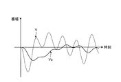
- FIG. 3 is a diagram comparing the surge waveform when the same surge is detected with the Rogowski coil and the surge waveform when detected with the iron core current transformer.
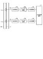
- FIG. 4 is a schematic diagram showing the configuration of an accident point locating device for a conventional gas insulated switchgear.
- FIG. 1 is a schematic diagram showing a configuration of an accident point locating device for a gas insulated switchgear according to the present embodiment.
- a tank 20 that is a part of a gas insulated switchgear and a central conductor 2 disposed in the tank 20 are shown.
- the center conductor 2 is an energization portion that extends in the axial direction of the tank 20 and through which a high voltage is applied and a current flows.
- An insulating gas is sealed in the tank 20.
- the accident point locating device includes Rogowski coils 1a and 1b, signal detection devices 30a and 30b, and a central processing unit 7.
- the Rogowski coils 1a and 1b are arranged at two points in the tank 20 with an interval in the axial direction and penetrated through the central conductor 2.
- the Rogowski coils 1a and 1b are sensors that output a voltage signal corresponding to the time differentiation of the current flowing through the center conductor 2, and are signals including a surge waveform that propagates through the center conductor 2 when an accident such as a ground fault or a short circuit occurs. Can be detected.
- the Rogowski coil 1a is connected to a signal detection device 30a disposed outside the gas-insulated switchgear through the wiring 3a.
- the signal detection device 30a is a device that detects a surge signal, and includes a band-pass filter circuit 4a, a detection level signal generation circuit 5a, and a comparison circuit 6a.
- the Rogowski coil 1b is connected to a signal detection device 30b disposed outside the gas-insulated switchgear through the wiring 3b.
- the signal detection device 30b is a device that detects a surge signal, and includes a band-pass filter circuit 4b, a detection level signal generation circuit 5b, and a comparison circuit 6b.
- the band-pass filter circuit 4a is a filter circuit that passes only the frequency component of the surge waveform, and does not pass the commercial frequency component applied to the center conductor 2. Specifically, the band-pass filter circuit 4a passes a frequency component in a band of 1 kHz to 10 kHz, for example. The same applies to the band-pass filter circuit 4b.
- the detection level signal generation circuit 5a is a circuit that generates a detection level signal that gives a detection level of a preset signal, that is, a detection level of a surge signal.
- the detection level signal is a signal having a certain level. The same applies to the detection level signal generation circuit 5b, and a detection level signal having the same magnitude as the detection level signal generation circuit 5a is generated.
- the comparison circuit 6a compares the output signal of the bandpass filter circuit 4a with the detection level signal output from the detection level signal generation circuit 5a, and when the magnitude of the output signal is greater than or equal to the detection level signal. When a square pulse signal is output and the magnitude of the output signal is less than the magnitude of the detection level signal, no signal is output. The same applies to the comparison circuit 6b.
- the central processing unit 7 is connected to the signal detection devices 30a and 30b.
- the central processing unit 7 includes a time difference detection unit 40 connected to the comparison circuits 6a and 6b, and an accident point location unit 41 connected to the time difference detection unit 40.
- the time difference detection unit 40 obtains the starting point of each pulse signal as the detection point of the surge waveform, calculates the time difference of each starting point, and calculates the calculation result. Output to the accident point location unit 41.
- the accident point location unit 41 uses the time difference output from the time difference detection unit 40, the propagation speed of the electromagnetic wave, and the distance between the measurement points (the distance between the Rogowski coils 1a and 1b) to measure the distance from the measurement point to the accident point. By calculating, the accident point is determined.
- t time
- ⁇ represents a circular ratio
- H represents mutual inductance
- I ′ (t) represents time differentiation of I (t).
- the output of the Rogowski coils 1a and 1b has a waveform with an amplitude proportional to the frequency f.
- FIG. 2A shows an example of output waveforms of the Rogowski coils 1a and 1b.
- FIG. 3 is a diagram comparing the surge waveform when the same surge is detected with the Rogowski coil and the surge waveform when detected with the iron core current transformer.
- the horizontal axis represents time
- the vertical axis represents amplitude
- V represents a voltage waveform when detected with a Rogowski coil
- Va represents a voltage waveform when detected with an iron core current transformer. Since V has a waveform with an amplitude proportional to the frequency as described above, the amplitude is several hundred times larger than Va.
- the output signal of the Rogowski coil 1a is input to the band-pass filter circuit 4a via the wiring 3a.
- the band pass filter circuit 4a passes only the frequency component of the surge waveform and outputs it to the comparison circuit 6a.
- FIG. 2B shows an example of the output waveform of the band pass filter circuit 4a. The current component of the commercial frequency flowing through the center conductor 2 is removed from the output waveform of the band pass filter circuit 4a.
- the comparison circuit 6a compares the output signal of the band pass filter circuit 4a with the detection level signal output from the detection level signal generation circuit 5a.
- FIG. 2C shows the output signal of the band-pass filter circuit 4a and the detection level signal (threshold value). In this case, the magnitude of the output signal of the band pass filter circuit 4a is larger than the threshold value.
- the comparison circuit 6a outputs a pulse signal only when the magnitude of the output signal is greater than or equal to the magnitude of the detection level signal as a result of the comparison.
- FIG. 2D shows an example of a pulse signal output from the comparison circuit 6a. The operations of the band pass filter circuit 4b, the detection level signal generation circuit 5b, and the comparison circuit 6b are the same.
- the output signals of the comparison circuits 6a and 6b are input to the time difference detection unit 40, respectively.
- the time difference detection unit 40 obtains the starting point (rising point) of each pulse signal as the detection point of the surge waveform, calculates the time difference between the starting points, The calculation result is output to the accident point location unit 41.
- FIG. 2 (e) shows how the time difference ⁇ t between the starting points is obtained from the pulse signal Pa output from the comparison circuit 6a and the pulse signal Pb output from the comparison circuit 6b.
- the accident point location unit 41 uses the time difference output from the time difference detection unit 40, the propagation speed of the electromagnetic wave, and the distance between the measurement points (the distance between the Rogowski coils 1a and 1b) to measure the distance from the measurement point to the accident point. By calculating, the accident point is determined.
- the surge waveform is output with the amplitude proportional to the frequency by the Rogowski coils 1a and 1b, and the signal having an unnecessary frequency is removed by the band pass filter circuits 4a and 4b. 3a, 3b, band pass filter circuits 4a, 4b, comparison circuits 6a, 6b, etc., the surge waveform has a higher amplitude ratio to the external noise.
- the present embodiment it is possible to set the detection level signal low, and it is possible to determine the accident point from the surge waveform at the time of a minute accident.
- the comparison circuits 6a and 6b compare the output signals of the band-pass filter circuits 4a and 4b with the detection level signals output from the detection level signal generation circuits 5a and 5b.
- the pulse signal is output only when the magnitude is equal to or larger than the detection level signal
- the present invention is not limited to the pulse signal, and a surge detection signal generally corresponding to a surge waveform may be output. That is, the shape of the output waveform is not limited to the pulse waveform, but the starting point is easier to detect when the pulse waveform is used.
- the time difference detection unit 40 obtains the starting point (rising point) of each surge detection signal as the detection point of the surge waveform, and calculates the time difference between the starting points. Then, the calculation result is output to the accident point location unit 41.
- FIG. 4 is a schematic diagram showing the configuration of an accident point locating device for a conventional gas insulated switchgear.
- the conventional fault location system is provided in a tank 20 of a gas-insulated switchgear, and includes iron core current transformers 11a and 11b that measure the current flowing through the center conductor 2, and iron core current transformers. Are connected to the transformers 11a and 11b via the wirings 13a and 13b, respectively, and the load resistors 14a and 14b for converting the current signals output from the iron core current transformers 11a and 11b to voltage signals and the load resistors 14a and 14b, respectively.
- AD converters 16a and 16b connected to filter circuits 15a and 15b for extracting a signal including a surge waveform from a voltage signal, and connected to filter circuits 15a and 15b, respectively, for converting an analog signal into a digital signal, and an AD converter A central processing unit 17 connected to 16a and 16b and processing a digital signal to locate an accident point.
- current signals proportional to the current transformation ratio are output from the iron core current transformers 11a and 11b with respect to the current flowing through the center conductor 2.
- the current transformation ratio is given by the winding ratio of the primary winding and the secondary winding of the iron core type current transformers 11a and 11b.
- the outputs of the iron core type current transformers 11a and 11b are generally proportional to the current transformation ratio, but the current transformation ratio is defined with respect to the commercial frequency, and the signal whose main component is a high frequency component such as a surge waveform is Output at a ratio smaller than the current transformation ratio.
- the output signals of the iron core current transformers 11a and 11b are converted from current signals to voltage signals by the load resistors 14a and 14b, respectively.
- the filter circuits 15a and 15b are low-pass filters, and pass signals of, for example, 10 kHz or less including a surge waveform.
- the AD converters 16 a and 16 b convert the surge waveform into a digital signal and output it to the central processing unit 17.
- the central processing unit 17 calculates the time difference between the detection points from the digital signals output from the AD converters 16a and 16b, with the starting point of each waveform as the detection point.
- the central processing unit 17 determines the accident point by calculating the distance to the accident point from the calculated time difference, the propagation speed of the electromagnetic wave, and the distance between the measurement points.
- the surge waveform is attenuated by the iron core current transformers 11a and 11b due to the high frequency components, and further attenuated by the filter circuits 15a and 15b.
- the amplitude of the generated surge waveform is originally small. Therefore, when the surge waveform is attenuated by the iron core current transformers 11a and 11b and the filter circuits 15a and 15b, the wirings 13a and 13b, the burden resistance 14a, 14b and the external noise generated by the filter circuits 15a, 15b, etc., become difficult, and it may be difficult for the central processing unit 17 to accurately detect the starting point of the surge waveform.
- the surge waveform is detected by using the differential detection type Rogowski coils 1a and 1b, thereby having an amplitude waveform proportional to the frequency of the surge waveform. It can be detected, the amplitude ratio of the surge waveform to external noise can be increased, and the fault point can be correctly determined even with a surge waveform at the time of a minute accident.
- the comparison circuits 6a and 6b perform threshold values by comparing analog signals. A pulse signal is output with respect to the above surge waveform, and processing is performed so that the starting point of the surge in the central processing unit 7 can be easily obtained. Therefore, the accuracy is high and no memory is required.
- the signal after passing through band-pass filter circuits 4a and 4b includes only the surge waveform.
- the surge waveform can be detected simply by comparing the magnitude of the detection level signal with the comparison circuits 6a and 6b.
- the filter circuits 15a and 15b which are low-pass filters, are used as in the conventional accident point locating device, the commercial frequency components flowing through the center conductor 2 cannot be excluded, so the comparison circuits 6a and 6b.
- the surge waveform cannot be detected simply by comparing the magnitude with the detection level signal.
- one of the current transformers arranged on both sides of the orientation section for locating the failure point of the electric circuit is an air core type current transformer, and the other is an iron core type current transformer.
- the air core type current transformer and the auxiliary air core type current transformer are provided as means for differentiating the waveform in order to obtain the starting point of the surge waveform, and detect a minute surge waveform as in this embodiment.
- a specific configuration for this is not disclosed.
- the configuration of signal processing is different from that of the present embodiment, such as providing an integrator after the air-core type current transformer.
- Patent Document 2 also describes the use of a current sensor such as a Rogowski coil as a means for determining the starting point of a surge waveform. However, as in this embodiment, a minute surge waveform is detected. A specific configuration for doing this is not disclosed.
- the present invention is useful as an accident point locating device for a gas insulated switchgear.
- 1a, 1b Rogowski coil 2 central conductor, 3a, 3b, 13a, 13b wiring, 4a, 4b band pass filter circuit, 5a, 5b detection level signal generation circuit, 6a, 6b comparison circuit, 7, 17 central processing unit, 11a, 11b Iron core type current transformer, 14a, 14b burden resistance, 15a, 15b filter circuit, 16a, 16b AD converter, 20 tank, 30a, 30b signal detector, 40 time difference detector, 41 accident point locator.
Landscapes
- Physics & Mathematics (AREA)
- Engineering & Computer Science (AREA)
- Mathematical Physics (AREA)
- Theoretical Computer Science (AREA)
- General Physics & Mathematics (AREA)
- Locating Faults (AREA)
Abstract
L'invention concerne un dispositif de localisation de défauts comprenant des bobines de Rogowski (1a, 1b), des circuits de filtre passe-bande (4a, 4b) permettant uniquement le passage de composants de fréquence de forme d'onde de surtension, des circuits de génération de signaux de niveau de détection (5a, 5b) pour générer des signaux de niveau de détection pour des signaux de surtension, des circuits de comparaison (6a, 6b) pour comparer respectivement les signaux de sortie provenant des circuits de filtre passe-bande (4a, 4b) et les signaux de niveau de détection émis par les circuits de génération de signaux de niveau de détection (5a, 5b) et délivrer un signal d'impulsion uniquement si l'amplitude d'un signal de sortie est supérieure ou égale à l'amplitude d'un signal de niveau de détection, une unité de détection de différence temporelle (40) pour calculer la différence temporelle entre les points de départ des signaux d'impulsion émis par les circuits de comparaison (6a, 6b), et une unité de localisation de défauts (41) pour localiser un défaut en fonction de la différence temporelle.
Priority Applications (1)
| Application Number | Priority Date | Filing Date | Title |
|---|---|---|---|
| PCT/JP2013/065988 WO2014199432A1 (fr) | 2013-06-10 | 2013-06-10 | Dispositif de localisation de défauts pour appareillage de commutation à isolation gazeuse |
Applications Claiming Priority (1)
| Application Number | Priority Date | Filing Date | Title |
|---|---|---|---|
| PCT/JP2013/065988 WO2014199432A1 (fr) | 2013-06-10 | 2013-06-10 | Dispositif de localisation de défauts pour appareillage de commutation à isolation gazeuse |
Publications (1)
| Publication Number | Publication Date |
|---|---|
| WO2014199432A1 true WO2014199432A1 (fr) | 2014-12-18 |
Family
ID=52021768
Family Applications (1)
| Application Number | Title | Priority Date | Filing Date |
|---|---|---|---|
| PCT/JP2013/065988 Ceased WO2014199432A1 (fr) | 2013-06-10 | 2013-06-10 | Dispositif de localisation de défauts pour appareillage de commutation à isolation gazeuse |
Country Status (1)
| Country | Link |
|---|---|
| WO (1) | WO2014199432A1 (fr) |
Cited By (1)
| Publication number | Priority date | Publication date | Assignee | Title |
|---|---|---|---|---|
| CN105628419A (zh) * | 2015-12-18 | 2016-06-01 | 国网安徽省电力公司 | 基于独立分量分析去噪的gis机械缺陷诊断系统及方法 |
Citations (4)
| Publication number | Priority date | Publication date | Assignee | Title |
|---|---|---|---|---|
| JPS57166812A (en) * | 1981-04-06 | 1982-10-14 | Mitsubishi Electric Corp | Enclosed gas insulating device |
| JPS63206668A (ja) * | 1987-02-23 | 1988-08-25 | Sumitomo Electric Ind Ltd | 送電線の事故点標定装置 |
| JP2008096336A (ja) * | 2006-10-13 | 2008-04-24 | J-Power Systems Corp | サージ電流簡易検出器 |
| JP2011122977A (ja) * | 2009-12-11 | 2011-06-23 | Mitsubishi Electric Corp | 部分放電位置標定装置および方法 |
-
2013
- 2013-06-10 WO PCT/JP2013/065988 patent/WO2014199432A1/fr not_active Ceased
Patent Citations (4)
| Publication number | Priority date | Publication date | Assignee | Title |
|---|---|---|---|---|
| JPS57166812A (en) * | 1981-04-06 | 1982-10-14 | Mitsubishi Electric Corp | Enclosed gas insulating device |
| JPS63206668A (ja) * | 1987-02-23 | 1988-08-25 | Sumitomo Electric Ind Ltd | 送電線の事故点標定装置 |
| JP2008096336A (ja) * | 2006-10-13 | 2008-04-24 | J-Power Systems Corp | サージ電流簡易検出器 |
| JP2011122977A (ja) * | 2009-12-11 | 2011-06-23 | Mitsubishi Electric Corp | 部分放電位置標定装置および方法 |
Cited By (1)
| Publication number | Priority date | Publication date | Assignee | Title |
|---|---|---|---|---|
| CN105628419A (zh) * | 2015-12-18 | 2016-06-01 | 国网安徽省电力公司 | 基于独立分量分析去噪的gis机械缺陷诊断系统及方法 |
Similar Documents
| Publication | Publication Date | Title |
|---|---|---|
| US8773139B2 (en) | High sensitivity differential current transformer for insulation health monitoring | |
| US20150160271A1 (en) | Current detection device | |
| US10502778B2 (en) | Method and apparatus for electric arc detection | |
| JP2017194290A (ja) | 変圧器鉄心の直流偏磁検出方法および変圧器鉄心の直流偏磁検出システム | |
| CN111771250B (zh) | 电流互感器 | |
| US11009557B2 (en) | Method and device for short-circuit monitoring of a three-phase load | |
| CN103630797B (zh) | 一种变压器匝间短路检测装置 | |
| JP6298581B2 (ja) | 電流検出装置及びこれを備えた変電設備 | |
| CN105957696B (zh) | 抗直流测量用电流互感器及制备方法 | |
| JP6265836B2 (ja) | 電流センサ検査システム、電流センサ検査方法 | |
| KR101952063B1 (ko) | 누설 전류 검출 장치 | |
| JP2002311061A (ja) | 電力用処理装置 | |
| CN103558446A (zh) | 一种过电压在线监测系统 | |
| JP2016194483A (ja) | 電流検知装置 | |
| JP2011158337A (ja) | 電流センサ | |
| CN108519508B (zh) | 一种测量交流与直流电流的比较仪 | |
| JP6092519B2 (ja) | 地絡検出装置および地絡検出方法 | |
| WO2014199432A1 (fr) | Dispositif de localisation de défauts pour appareillage de commutation à isolation gazeuse | |
| WO2018034260A1 (fr) | Système, dispositif et procédé de détection de phase ouverte | |
| JP2007316042A (ja) | 直流電流センサー及び直流電流検出装置 | |
| JP6461698B2 (ja) | 漏電検出装置及び漏電検出方法 | |
| JP2018031672A (ja) | 電力計測システム、電力計測用サブシステム、及び判定方法 | |
| JPH09152462A (ja) | 変圧器の部分放電検出方法 | |
| JP2009047663A (ja) | 電気機器の部分放電検出方法とその装置 | |
| JP2017204973A (ja) | 欠相検知システム、欠相検知装置および欠相検知方法 |
Legal Events
| Date | Code | Title | Description |
|---|---|---|---|
| 121 | Ep: the epo has been informed by wipo that ep was designated in this application |
Ref document number: 13886828 Country of ref document: EP Kind code of ref document: A1 |
|
| NENP | Non-entry into the national phase |
Ref country code: DE |
|
| 122 | Ep: pct application non-entry in european phase |
Ref document number: 13886828 Country of ref document: EP Kind code of ref document: A1 |
|
| NENP | Non-entry into the national phase |
Ref country code: JP |