WO2014199435A1 - Dispositif de réglage de position de protège-aiguille et navette à rotation horizontale complète - Google Patents
Dispositif de réglage de position de protège-aiguille et navette à rotation horizontale complète Download PDFInfo
- Publication number
- WO2014199435A1 WO2014199435A1 PCT/JP2013/066001 JP2013066001W WO2014199435A1 WO 2014199435 A1 WO2014199435 A1 WO 2014199435A1 JP 2013066001 W JP2013066001 W JP 2013066001W WO 2014199435 A1 WO2014199435 A1 WO 2014199435A1
- Authority
- WO
- WIPO (PCT)
- Prior art keywords
- needle
- cam
- cam member
- hole
- hook
- Prior art date
- Legal status (The legal status is an assumption and is not a legal conclusion. Google has not performed a legal analysis and makes no representation as to the accuracy of the status listed.)
- Ceased
Links
Images


Classifications
-
- D—TEXTILES; PAPER
- D05—SEWING; EMBROIDERING; TUFTING
- D05B—SEWING
- D05B57/00—Loop takers, e.g. loopers
- D05B57/08—Loop takers, e.g. loopers for lock-stitch sewing machines
- D05B57/10—Shuttles
- D05B57/14—Shuttles with rotary hooks
-
- D—TEXTILES; PAPER
- D05—SEWING; EMBROIDERING; TUFTING
- D05B—SEWING
- D05B69/00—Driving-gear; Control devices
Definitions
- the present invention relates to a needle-feeding position adjusting device for a sewing machine and a horizontal full rotation hook.
- FIG. 14 is a perspective view showing a conventional horizontal full rotation hook 1.
- the horizontal all-rotation rotary hook 1 of the sewing machine used for sewing work has a configuration in which an inner hook 3 containing a bobbin is fitted in an outer hook 2 that can rotate around a vertical axis.
- the outer hook 2 is driven to rotate, the needle thread provided by the needle is captured by the sword tip 4, and the bobbin thread wound around the bobbin and the needle thread are engaged with each other, Forming eyes.
- the outer shuttle 2 of the horizontal full rotation shuttle 1 forming the stitch is provided with a needle moving plate 5 so that the needle can be guided.
- the horizontal full rotation hook 1 is configured to guide the reciprocating movement path of the needle by the needle moving plate 5, but depending on the radial position of the needle moving plate 5 with respect to the rotation axis of the outer hook, the thickness or the like may be changed.
- the needles may undesirably abut against the needle moving plate 5 and elastically deform, and the needles may contact the sword tip 4 in some cases.
- Changing the needle from a thicker one to a thinner one increases the distance between the needle and the needle moving plate, and changing the needle from a thinner one to a thicker one decreases the distance between the needle and the needle moving plate and retains the needle thread.
- the needle that reciprocates is bent due to a change in the tension of the needle thread.
- the outer hook is equipped with a needle moving position adjusting device.
- a cam member made of an eccentric cam and rotatable around a cam axis is provided on an outer hook where a sword tip is formed so as to abut on the inner surface of the needle moving plate.
- a needle shift position adjusting device that adjusts the radial entry / exit position of the needle shift plate by changing the rotation position.
- a plurality of convex portions are formed on the outer peripheral portion of the cam member, and the cam member is prevented from rotating by fitting the convex portions into a concave portion formed in the needle shift plate. .
- the distance from the cam axis to the position where the convex portion of the cam member abuts on the needle contact plate is different. Therefore, by changing the rotation angle of the cam member, it is possible to adjust the radial entry / exit position of the needle gathering plate, so that the needle gathering plate can be optimally guided according to the type of needle thickness. It can be positioned and positioned. This prevents the needle from unnecessarily coming into contact with the needle moving plate and elastically deforming during sewing operation, or the needle from coming into contact with the sword tip. Can be prevented in advance.
- the needle shift position adjusting device described in Patent Document 1 prevents the cam member from rotating by fitting a plurality of convex portions formed on the outer peripheral portion of the cam member into the concave portions formed on the needle shift plate.
- the radial position of the needle moving plate is determined by the rotation angle of the cam member. Therefore, in the prior art described in Patent Document 1, the minimum width in which the position of the needle plate in the radial direction can be adjusted depends on the formation interval of the convex portions of the cam member. That is, there is a problem that it is difficult to adjust the position in the radial direction of the needle moving plate more precisely than the minimum width defined by the formation interval of the convex portions. Further, there is a problem that the position of the needle moving plate can be adjusted only in the adjustment width unit defined by the formation interval of the convex portions of the cam member.
- An object of the present invention is to provide a needle moving position adjusting device that can adjust the position of the needle moving plate according to the type of the needle more precisely.
- the present invention relates to a sword tip that is fixed to a lower shaft that is driven to rotate about a rotation axis parallel to the axis of a needle bar to which a sewing needle is attached, and that has a tapered shape with a tip end directed downstream in the rotation direction of the lower shaft.
- a horizontal full rotation provided with an outer hook that is provided with a tapered needle tip plate with a tip end facing the upstream side in the rotational direction, on the downstream side in the rotational direction with respect to the sword tip portion.
- a needle shift position adjusting device provided in a hook
- a cam member that is disposed on the inner side of the needle shift plate of the outer bite and contacts the needle shift plate;
- the cam member includes a cam attachment plate that is rotatably attached around a cam axis parallel to the rotation axis and is provided on the outer hook so as to be displaceable in a direction perpendicular to the rotation axis.
- bolt which has the 1st axial part screwed by the said outer hook, A second bolt having a second shaft portion screwed onto the outer hook; A first through hole through which the first shaft portion can be inserted and a second shaft portion can be inserted into the cam mounting plate, and the cam member extends in a direction in which the cam member approaches and separates from the needle moving plate.
- a second through hole comprising a long hole is formed, It is preferable that a distance between the first through hole and the cam axis is shorter than a distance between the first through hole and the second through hole.
- the needle moving plate has a recess on the side in contact with the cam member, It is preferable that the cam member has a plurality of convex portions that are formed on the outer peripheral portion at intervals in the circumferential direction and can be fitted into the concave portion.
- the cam member is preferably an eccentric cam.
- the present invention includes even a horizontal full rotation characterized by including any one of the above-described needle shift position adjusting devices.
- an outer shuttle is fixed to a lower shaft that is driven to rotate about a rotational axis parallel to the axis of a needle bar to which a sewing needle (hereinafter simply referred to as a “needle”) is attached in a horizontal full rotation shuttle.
- the outer hook has a sword tip that tapers toward the downstream side in the rotational direction, and is tapered with the tip portion toward the downstream side in the rotational direction and the upstream side in the rotational direction.
- a needle moving plate is provided.
- a needle shift position adjusting device for adjusting the position of the needle moving plate with respect to the needle by displacing the needle moving plate toward or away from the movement path of the needle is provided on the outer rotary hook of the horizontal full rotation hook. .
- the cam shift plate includes a cam member that is disposed inside the outer shuttle and contacts the needle shift plate, and a cam mounting plate to which the cam member is rotatably mounted. Since the outer hook is provided so as to be displaceable in a direction perpendicular to the rotation axis, the fixing position of the cam mounting plate relative to the outer hook can be moved when the cam mounting plate is fixed to the outer hook.
- the fixing position of the cam attachment plate is changed, the radial position of the cam member attached to the cam attachment plate is changed, and the contact position of the cam member with respect to the needle moving plate is changed in the radial direction.
- the radial position of the needle gathering plate can be adjusted to the optimum position according to the type of needle, so that suitable needle guidance during sewing operation is realized, and the needle becomes the needle gathering plate. It is possible to prevent undesired contact and elastic deformation, and to prevent problems caused by contact between the needle and the sword tip.
- first bolt having a first shaft portion screwed to an outer hook and a second bolt having a second shaft portion, and the first shaft portion can be inserted into the cam mounting plate.
- a first through hole and a second through hole through which the second shaft portion can be inserted are formed.
- the second through hole is composed of a long hole extending in a direction in which the cam member approaches and separates from the needle moving plate. Further, the distance between the first through hole and the cam axis is set to be shorter than the distance between the first through hole and the second through hole.
- the radial position of the cam member is changed by displacing the fixed position of the cam mounting plate within the formation range of the long hole that is the second through hole with reference to the position of the first through hole.
- the radial position of the needle moving plate can be adjusted. That is, it is possible to adjust the radial position of the needle moving plate based on the amount of displacement of the fixed position of the cam mounting plate.
- the position of the first through hole is used as a reference. Since the amount of displacement of the cam member can be reduced compared to the amount of displacement when the fixed position of the cam mounting plate is moved within the formation range of the long hole of the second through-hole, the more precise movement of the needle moving plate can be achieved. Adjustment is possible. Further, since the movement of the fixed position of the cam mounting plate can be continuously performed, the displacement amount of the needle moving plate can be continuously adjusted.
- a plurality of convex portions are formed on the outer peripheral portion of the cam member, and the convex portions are fitted into the concave portions formed on the needle moving plate.
- the cam member is prevented from rotating, the contact state with respect to the needle moving plate is maintained, and an undesired change in the position of the needle moving plate due to the rotation of the cam member is prevented.
- the cam member does not require another configuration and operation for preventing rotation, the configuration for adjusting the position of the needle plate can be simplified and the operation can be facilitated.
- the anti-rotation of the cam member is not released by vibration due to a sewing operation or the like, and the cam member is accurately positioned at a suitable anti-rotation position. be able to.
- the cam member is an eccentric cam, so that the position of the needle moving plate is adjusted in addition to the change of the fixed position of the cam mounting plate relative to the outer hook, and the rotation angle of the cam member with respect to the cam mounting plate Therefore, it is possible to make precise and wide adjustments.
- FIG. 1 is a front view of a horizontal full rotation hook 10 according to an embodiment of the present invention.
- FIG. 2 is a cross-sectional view of the horizontal full rotation hook 10 taken along the line II-II in FIG. 1.
- 1 is a plan view of a horizontal full rotation hook 10 according to an embodiment of the present invention. It is a bottom view of the horizontal full rotation hook 10 which concerns on one Embodiment of this invention. It is a front view which shows the outer hook 20 of the horizontal full rotation hook 10 which concerns on one Embodiment of this invention. It is a left view which shows the outer hook 20 of the horizontal full rotation hook 10 which concerns on one Embodiment of this invention.
- FIG. 6 is a cross-sectional view of the outer hook 20 taken along the line VII-VII in FIG. 5.
- FIG. 4 is a bottom view of the horizontal full rotation shuttle 10 according to the embodiment of the present invention, and shows a state in which the cam mounting plate 41 is fixed at a position where the cam member 50 is farthest from the needle moving plate 26. It is a top view of the horizontal full rotation hook 10 shown in FIG. FIG.
- FIG. 4 is a bottom view of the horizontal full rotation shuttle 10 according to the embodiment of the present invention, in which the cam mounting plate 41 is fixed so that the cam member 50 contacts the needle moving plate 26 at the farthest position on the radially outer side. Is shown.
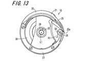
- FIG. 13 is a plan view of the horizontal full rotation hook 10 shown in FIG. 12. It is a perspective view which shows the conventional horizontal full rotation hook 1.
- FIG. 13 is a plan view of the horizontal full rotation hook 10 shown in FIG. 12. It is a perspective view which shows the conventional horizontal full rotation hook 1.
- FIGS. 1 to 9 relate to an embodiment of the present invention
- FIG. 1 is a front view of a horizontal full rotation hook 10
- FIG. 2 is a horizontal full rotation viewed from the section line II-II in FIG. 3 is a cross-sectional view of the rotary hook 10
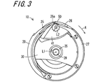
- FIG. 3 is a plan view of the horizontal full rotary hook 10
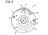
- FIG. 4 is a bottom view of the horizontal full rotary hook 10
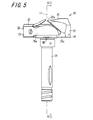
- FIG. 5 is a front view of the outer rotary hook 10 of the horizontal full rotary hook 10
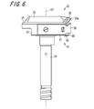
- FIG. FIG. 7 is a cross-sectional view of the outer hook 20 viewed from the cutting plane line VII-VII in FIG. 5
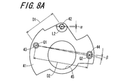
- FIG. 8A is a front view of the cam mounting plate 41
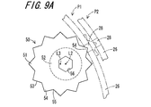
- FIG. 9A is a plan view of the cam member 50
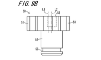
- FIG. 9B is a front view thereof.
- the horizontal all-over rotary hook 10 up to the sewing machine is provided in the sewing machine, and is used to sew a workpiece by forming a seam in cooperation with other components such as a needle and a balance.
- the sewing machine is provided with a lower shaft that is rotationally driven around a rotation axis L1 parallel to the axis of the needle bar to which the needle is detachably attached, and a horizontal full rotation hook 10 is provided on the lower shaft.
- the rotary hook 10 is provided with the needle position adjusting device 40 according to this embodiment.
- the horizontal full rotation hook 10 includes an outer hook 20 that is rotatably provided around a vertical rotation axis L1, and an inner hook 30 that is fitted into the outer hook 20 and is rotatably held independently of the outer hook 20. It is comprised including.
- the outer hook 20 has an outer hook body 21 and a rotary shaft 24 provided integrally therewith.
- the rotating shaft 24 is rotatably connected to the lower shaft of the sewing machine.
- the outer axis body 21 and the rotation axis L1 of the rotation shaft 24 are vertical.
- the outer hook main body 21 is formed with a short cylindrical peripheral wall 22 that is generally open at the top and bottom, and a sword tip that is formed to be continuous with the peripheral wall 22 and has a tapered shape with the tip portion directed downstream in the rotational direction A of the outer hook 20. It includes a portion 25 and a needle moving plate 26 that is disposed further downstream in the rotational direction A than the sword tip portion 25 and has a tip portion tapered toward the upstream side in the rotational direction A.
- a circumferential step portion 23 is formed on the inner peripheral surface of the peripheral wall 22.
- the needle moving plate 26 is an arc-shaped part, one end of which is screwed to the outer shuttle main body 21 and the other end is a free end, and the movement path of the needle that reciprocates in the vertical direction is positioned on the outer peripheral side thereof. Positioned to do so.
- the needle moving plate 26 is arranged so that the tip of the sword tip portion 25 is positioned at an intermediate portion c between the base end portion 26a and the free end portion 26b.
- the needle moving plate 26 can be elastically deformed, and the radial entry / exit position perpendicular to the rotation axis L1 of the intermediate portion 26c can be adjusted.
- the inner hook 30 is provided with a substantially cylindrical short peripheral wall portion 31, a bottom portion 32 provided so as to close one end portion in the axial direction of the peripheral wall portion 31, and a central portion of the bottom portion 32, and is housed inside. And a stud 35 for holding the bobbin around which the bobbin thread is wound.
- the inner shuttle 30 is prevented from rotating by following a rotation of the outer shuttle 20 by a non-rotating member (not shown) connected to the machine body of the sewing machine.
- a rail 33 extending in the circumferential direction is formed on the outer peripheral portion of the peripheral wall portion 31 of the inner shuttle 30.
- the rail 33 of the inner hook 30 is arranged so as to fit into the step portion 23 of the outer hook 20 and is pressed against the upper end surface of the peripheral wall 22 of the outer hook 20.
- the member 27 is fixed and held so that the inner hook 30 does not fall off the outer hook 20.
- the step portion 23 forms a rail groove by fixing a presser member 27 to the upper end surface of the peripheral wall portion 31, and is rotatable in a state in which the rail 33 of the inner hook 30 is fitted in the rail groove. Retained.
- the stud 35 of the inner hook 30 is a substantially cylindrical member having upper and lower ends that are coaxial with the rotation axis L ⁇ b> 1.
- the guide shaft 36 and the guide shaft 36 are directed toward the upper end opening 35 a of the stud 35.
- a latch spring 37 that elastically presses, a latch pin 38 disposed in the vicinity of the upper end opening 35a, and a latch piece 39 for preventing the bobbin from falling off the inner hook 30 are provided.
- the latch spring 37 is realized by a cylindrical compression coil spring.
- the latch pin 38 is inserted through the proximal end portion of the latch piece 39 and connects the latch piece 39 to the stud 35 so as to be angularly displaceable.
- the latch piece 39 In the latch piece 39, one end portion of the guide shaft 36 is elastically brought into contact with the base end portion by the elastic force of the latch spring 37. As a result, the latch piece 39 is rotated around the axis of the latch pin 38 and is stable in two positions, ie, an open position substantially parallel to the stud 35 and a closed position substantially parallel to the radial direction extending from the stud 35 to the peripheral wall portion 31. Configured to let The open position of the latch piece 39 is a position where the bobbin can be freely attached to and detached from the inner rack 30, and the closed position is a position where the bobbin is held so as not to fall into the inner rack 30.
- a spring is arranged around the stud 35 and the bobbin is elastically pressed toward the upper end opening 35a, thereby suppressing the rattling of the bobbin and preventing fluctuations in the tension of the lower thread. You may make it do.
- the horizontal rotary rotary shuttle 10 When the rotational force is transmitted from the lower shaft of the sewing machine to the rotary shaft 24, the horizontal rotary rotary shuttle 10 is rotationally driven in the rotational direction A around the rotational axis L1 in synchronization with the vertical movement of the needle. .
- the outer hook 20 is rotationally driven in a state where the inner hook 30 is prevented from rotating.
- the outer hook body 21 is formed with a sword tip 25 projecting in the rotation direction A, which is one circumferential direction, on the peripheral wall 22, and when the outer hook 20 is driven to rotate, the workpiece is inserted by the needle.
- the resulting loop of needle thread is captured by the sword tip 25 and threaded around the inner hook 30.
- the needle thread and the bobbin thread are engaged, and the needle thread is pulled up by the balance, so that a stitch is formed.
- the horizontal full rotation hook 10 is further provided with a needle shifting position adjusting device 40 including a cam attachment plate 41 fixed to the outer hook 20 and a cam member 50 attached to the cam attachment plate 41.
- the cam member 50 is a member that is disposed on the inner side of the needle guide plate 26 of the outer hook 20 and contacts the needle guide plate 26 from the inner side.
- the cam mounting plate 41 is fixed to the outer shuttle 20 with the cam member 50 mounted rotatably.
- the cam mounting plate 41 of the present embodiment is a plate-like member having a shape covering a part of the bottom side opening of the outer rack 20, and the cam member 50 is rotatable.
- the second through hole 44 is a long hole that extends in a direction in which the cam member 50 approaches and separates from the needle moving plate 26.
- the cam attachment portion 42 is a through hole through which the cam shaft 52 of the cam member 50 is inserted.
- the cam member 50 is firmly attached to the portion surrounding the cam attachment portion 42 by providing a thicker support portion 46 than the other portions.
- the cam member 50 is a member that is disposed on the inner side of the needle moving plate 26, that is, closer to the rotation axis L ⁇ b> 1 and is in contact with the needle moving plate 26, and is disposed closer to the inner side than the moving path of the tip 25 a of the sword tip 25. Is done.
- the cam attachment plate 41 to which the cam member 50 is rotatably attached is fixed to the outer hook body 21 so as to partially close the bottom opening of the outer hook body 21.
- the cam member 50 is configured by integrally forming a cam body 51 and a cam shaft 52.
- the cam member 50 of this example is a so-called eccentric cam, and the axis L3 of the cam body 51 and the cam axis L2 of the cam shaft 52 are eccentric.
- the cam member 50 is made of, for example, a hard metal such as stainless steel, a chromium alloy, an SK material (carbon tool steel), or an SKS material (alloy tool steel).
- the cam body 51 may have a cylindrical cam as the outer peripheral portion 53 serving as a cam surface.
- a star that repeats convex and concave alternately in the circumferential direction. You may form in the shape of a polygonal polygonal cylinder.
- Such a cam body 51 can be formed by knurling.
- the cam body 51 is formed by alternately forming convex portions 54 whose outer peripheral cam surfaces are convex outward in the radial direction and concave portions 55 concave inward in the radial direction. Configured.
- An engaging recess 56 such as a hexagonal hole is formed on the upper surface side of the cam body 51.
- the axis of the engaging recess 56 coincides with the cam axis L2 of the cam shaft 52.
- the cam shaft 52 has a columnar shape, and a locking groove 57 extending in the circumferential direction is formed at a tip portion which is an end portion on the opposite side to the cam body 51.
- the cam member 50 inserts the cam shaft 52 into the cam mounting portion 42 of the cam mounting plate 41 so that the tip portion protrudes, and a locking groove 57 at the protruding tip portion is inserted into, for example, a C ring or E ring.
- the cam member 50 can be attached to the cam attachment plate 41 so that it can rotate and does not easily fall off. In this way, the cam member 50 is supported by the cam mounting plate 41 so as to be rotatable around the axis L2 of the camshaft 52 (hereinafter sometimes referred to as “cam axis”).
- the cam member 50 is rotated around the cam axis L ⁇ b> 2 of the cam shaft 52 in a state where a tool such as a hexagon wrench is engaged with the engagement recess 56 and is mounted on the outer shuttle 20. It is configured to be possible.
- the outer peripheral portion 53 of the cam main body 51 is in contact with the intermediate portion 26c of the needle moving plate 26. Since the cam main body 51 is an eccentric cam, when the cam member 50 is rotated, the distance between the cam axis L21 and the position where the cam main body 51 contacts the needle moving plate 26 changes depending on the rotation angle. Therefore, by adjusting the angular position of the cam member 50, the position in the radial direction with respect to the rotation axis L1 of the needle moving plate 26 can be adjusted to positions P1 and P2 exemplified by phantom lines in FIG. 9A, for example.
- the needle moving plate 26 has a fitting groove 28 formed in the vicinity of the tip 25a of the sword tip 25 in the circumferential direction, and the cam body 51 contacts the needle moving plate 26. At this time, one of the plurality of convex portions 54 is fitted into the fitting groove 28. At this time, the tops of the other two convex portions 54 arranged on both sides in the circumferential direction of the convex portion 54 fitted in the fitting groove 28 are arranged on both sides of the fitting groove 28 on the inner peripheral surface portion of the needle moving plate 26. Each abuts and is supported stably. With such a configuration, when one convex portion 54 is fitted into the fitting groove 28, rotation of the cam member 50 is suppressed and a stable state is obtained.
- the cam main body 51 has a plurality of convex portions 54 formed at intervals in the circumferential direction, and one of the convex portions 54 fits into the fitting groove 28 of the needle moving plate 26.
- a cam member 50 may be configured such that the tip of each convex portion 54 is inscribed in a spiral locus whose radius increases in proportion to the rotation angle around the cam axis L2.
- the cam mounting plate 41 to which the cam member 50 is rotatably mounted is fixed to the bottom portion 21a of the outer rack main body 21 by the first bolt 61 and the second bolt 62 as shown in FIG. In this state, the cam member 50 is disposed on the inner side of the outer hook main body 21 or in the vicinity of the cam main body 51 in contact with the needle moving plate 26.
- the first through hole 43 is circular
- the second through hole 44 is a long hole.
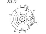
- FIG. 10 is a bottom view of the horizontal full rotation hook 10 and shows a state in which the cam mounting plate 41 is fixed at a position where the cam member 50 is farthest from the needle moving plate 26, and
- FIG. FIG. 12 is a bottom view of the horizontal all-rotation hook 10 shown in FIG. 12, and is a bottom view of the horizontal all-turn hook 10 so that the cam member 50 contacts the needle moving plate 26 at the farthest position radially outward.
- FIG. 13 shows a state in which the plate 41 is fixed
- FIG. 13 is a plan view of the horizontal full rotation hook 10 shown in FIG.
- the distance D1 between the central axis Q1 of the first through hole 43 and the cam axis L2 of the cam member 50 attached to the cam attachment portion 42 is equal to the central axis Q1 of the first through hole 43 and the first axial hole Q1. Since the configuration is shorter than the distance D2 between the central axis Q2 of the two through holes 44, the effect of precisely adjusting the radial position where the cam member 50 contacts the needle moving plate 26 is exhibited.
- the first bolt 61 and the second bolt 62 are inserted into the first through hole 43 and the second through hole 44, respectively, and screwed to the outer cam 20, and the cam is mounted around the center axis Q1.
- the position where the cam mounting plate 41 is fixed to the outer hook 20 is displaced within the formation range of the second through hole 44 which is a long hole, whereby the contact position of the cam member 50 with the needle moving plate 26 is reached. Can be displaced in the radial direction to adjust the radial entry / exit position of the needle moving plate 26 in the radial direction.
- the needle gathering plate 26 is placed at a position suitable for the needle, such as the thickness and shape of the needle, particularly at the position where the sword tip 25 is formed in the circumferential direction.
- a needle shift position adjusting device that can be arranged at a suitable position and can guide the needle to a suitable needle shift position for capturing the needle thread by the sword tip 25 can be realized. Therefore, it is possible to prevent the needle from being guided to be elastically deformed by undesirably coming into contact with the needle moving plate 26 during the sewing operation, and the contact of the needle with the sword tip 25 can be prevented. Therefore, it is possible to prevent problems caused by contact between the needle and the sword tip 25, that is, poor sewing and damage to parts.
- the distance D1 between the center axis Q1 of the first through hole 43 and the cam axis L2 of the cam member 50 attached to the cam attachment portion 42 is set to the center axis Q1 of the first through hole 43 and the second through hole 44. Since the distance is shorter than the distance D2 between the central axis Q2 and the cam member 50, the radial position where the cam member 50 comes into contact with the needle moving plate 26 can be adjusted precisely.
- the outer peripheral portion 53 of the cam member 50 is formed with a plurality of convex portions 54, and the convex portions 54 are elastically fitted into the fitting grooves 28 formed in the needle moving plate 26. As a result, the cam member 50 is prevented from rotating and stably stops.
- the cam member 50 does not require a configuration and operation for preventing rotation, and the angular position is prevented from changing undesirably.
- the anti-rotation structure having the above-described configuration simplifies the configuration for adjusting the position of the needle movement plate 26 and facilitates the adjustment operation of the needle movement position. Further, in the anti-rotation structure having the above-described configuration, the anti-rotation is not released by vibration due to a sewing operation or the like, and the anti-rotation can be suitably maintained.
- the present invention is not limited to the above-described embodiment.
- the shape and type of the cam member 50 are not limited, and the cam member 50 may have a configuration using other shapes and types as long as the position of the needle moving plate 26 can be adjusted.
Landscapes
- Engineering & Computer Science (AREA)
- Textile Engineering (AREA)
- Mechanical Engineering (AREA)
- Sewing Machines And Sewing (AREA)
Abstract
La présente invention concerne un dispositif (40) de réglage de position de protège-aiguille capable de régler la position radiale d'une plaque protège-aiguille (26) avec une grande précision. Le dispositif (40) de réglage de position de protège-aiguille est installé sur un crochet tournant (20) dans lequel sont disposés une partie (25) de pointe de lame aminci vers le côté aval d'un sens de rotation et une plaque protège-aiguille (26) aminci vers le côté amont du sens de rotation, et comprend un élément (50) de came disposé intérieurement par rapport à la plaque protège-aiguille (26) et en contact avec la plaque protège-aiguille (26) et une plaque (41) de montage de came qui peut être déplacée dans une direction perpendiculaire à un axe de rotation (L1). Dans la plaque (41) de montage de came sont pratiqués un premier trou débouchant (43) et un deuxième trou débouchant (44) constituant un long trou s'étendant dans la direction du rapprochement et de l'éloignement par rapport à l'élément de came, la distance (D1) entre l'axe central (Q1) du premier trou débouchant (43) et un axe (L2) de la came étant plus courte que la distance entre l'axe central (Q1) du premier trou débouchant (43) et l'axe central (Q2) du deuxième trou débouchant (44).
Priority Applications (1)
| Application Number | Priority Date | Filing Date | Title |
|---|---|---|---|
| PCT/JP2013/066001 WO2014199435A1 (fr) | 2013-06-10 | 2013-06-10 | Dispositif de réglage de position de protège-aiguille et navette à rotation horizontale complète |
Applications Claiming Priority (1)
| Application Number | Priority Date | Filing Date | Title |
|---|---|---|---|
| PCT/JP2013/066001 WO2014199435A1 (fr) | 2013-06-10 | 2013-06-10 | Dispositif de réglage de position de protège-aiguille et navette à rotation horizontale complète |
Publications (1)
| Publication Number | Publication Date |
|---|---|
| WO2014199435A1 true WO2014199435A1 (fr) | 2014-12-18 |
Family
ID=52021771
Family Applications (1)
| Application Number | Title | Priority Date | Filing Date |
|---|---|---|---|
| PCT/JP2013/066001 Ceased WO2014199435A1 (fr) | 2013-06-10 | 2013-06-10 | Dispositif de réglage de position de protège-aiguille et navette à rotation horizontale complète |
Country Status (1)
| Country | Link |
|---|---|
| WO (1) | WO2014199435A1 (fr) |
Citations (4)
| Publication number | Priority date | Publication date | Assignee | Title |
|---|---|---|---|---|
| JPS578077U (fr) * | 1980-06-06 | 1982-01-16 | ||
| JPS58195587A (ja) * | 1982-05-04 | 1983-11-14 | デユルコツプウエルケ・ゲゼルシヤフト・ミト・ベシユレンクテル・ハフツング | 調整可能な針受けをもつ2重本縫ル−パ |
| JPS63107688U (fr) * | 1986-12-27 | 1988-07-11 | ||
| JP2005261847A (ja) * | 2004-03-22 | 2005-09-29 | Hirose Mfg Co Ltd | ミシンのかまおよび外かま |
-
2013
- 2013-06-10 WO PCT/JP2013/066001 patent/WO2014199435A1/fr not_active Ceased
Patent Citations (4)
| Publication number | Priority date | Publication date | Assignee | Title |
|---|---|---|---|---|
| JPS578077U (fr) * | 1980-06-06 | 1982-01-16 | ||
| JPS58195587A (ja) * | 1982-05-04 | 1983-11-14 | デユルコツプウエルケ・ゲゼルシヤフト・ミト・ベシユレンクテル・ハフツング | 調整可能な針受けをもつ2重本縫ル−パ |
| JPS63107688U (fr) * | 1986-12-27 | 1988-07-11 | ||
| JP2005261847A (ja) * | 2004-03-22 | 2005-09-29 | Hirose Mfg Co Ltd | ミシンのかまおよび外かま |
Similar Documents
| Publication | Publication Date | Title |
|---|---|---|
| US10260186B2 (en) | Cutting device for a sewing machine | |
| US9770779B2 (en) | Tip dressing cutter | |
| TWI632266B (zh) | 以偏心驅動活動舌件座之定位結構 | |
| WO2014199435A1 (fr) | Dispositif de réglage de position de protège-aiguille et navette à rotation horizontale complète | |
| US7533547B2 (en) | Cutting needle with interchangeable knife | |
| TWI374209B (fr) | ||
| EP1828464B1 (fr) | Crochet rotatif horizontal pour machine a coudre | |
| CN219410149U (zh) | 一种旋梭梭架、旋梭结构及其缝纫机 | |
| US5433159A (en) | Horizontal rotating hook for sewing machine | |
| JPH0268096A (ja) | 本縫いミシンの全回転かま | |
| JP6395864B2 (ja) | 垂直全回転かま | |
| JP2005261847A (ja) | ミシンのかまおよび外かま | |
| EP1443137A1 (fr) | Navette rotative horizontale pour machine à coudre | |
| JP6343278B2 (ja) | 針寄せ位置調整装置 | |
| JP6698568B2 (ja) | 水平全回転かま | |
| JP6733867B2 (ja) | ミシンの水平釜 | |
| US7069868B2 (en) | Central bobbin shuttle | |
| JP2008119244A (ja) | ミシンの布切り装置 | |
| JP2009219522A (ja) | ミシンの中釜回り止め部材取付構造 | |
| JPH0550955B2 (fr) | ||
| JP2009261949A (ja) | ボビンハウジング、この種のボビンハウジングを備えて成るフック、及び、この種のフックを備えて成るミシン | |
| JP2003038881A (ja) | ミシン | |
| JP2008132006A (ja) | ミシン | |
| JP5438310B2 (ja) | 水平回転釜 | |
| JPH0510789Y2 (fr) |
Legal Events
| Date | Code | Title | Description |
|---|---|---|---|
| 121 | Ep: the epo has been informed by wipo that ep was designated in this application |
Ref document number: 13886946 Country of ref document: EP Kind code of ref document: A1 |
|
| NENP | Non-entry into the national phase |
Ref country code: DE |
|
| 122 | Ep: pct application non-entry in european phase |
Ref document number: 13886946 Country of ref document: EP Kind code of ref document: A1 |
|
| NENP | Non-entry into the national phase |
Ref country code: JP |