WO2014199779A1 - 車両の乗員又は歩行者を保護するための保護装置を制御する制御装置、及び制御システム - Google Patents
車両の乗員又は歩行者を保護するための保護装置を制御する制御装置、及び制御システム Download PDFInfo
- Publication number
- WO2014199779A1 WO2014199779A1 PCT/JP2014/063202 JP2014063202W WO2014199779A1 WO 2014199779 A1 WO2014199779 A1 WO 2014199779A1 JP 2014063202 W JP2014063202 W JP 2014063202W WO 2014199779 A1 WO2014199779 A1 WO 2014199779A1
- Authority
- WO
- WIPO (PCT)
- Prior art keywords
- sensor
- unit
- failure
- external sensor
- control device
- Prior art date
- Legal status (The legal status is an assumption and is not a legal conclusion. Google has not performed a legal analysis and makes no representation as to the accuracy of the status listed.)
- Ceased
Links
Images







Classifications
-
- G—PHYSICS
- G07—CHECKING-DEVICES
- G07C—TIME OR ATTENDANCE REGISTERS; REGISTERING OR INDICATING THE WORKING OF MACHINES; GENERATING RANDOM NUMBERS; VOTING OR LOTTERY APPARATUS; ARRANGEMENTS, SYSTEMS OR APPARATUS FOR CHECKING NOT PROVIDED FOR ELSEWHERE
- G07C5/00—Registering or indicating the working of vehicles
- G07C5/08—Registering or indicating performance data other than driving, working, idle, or waiting time, with or without registering driving, working, idle or waiting time
- G07C5/0841—Registering performance data
-
- B—PERFORMING OPERATIONS; TRANSPORTING
- B60—VEHICLES IN GENERAL
- B60R—VEHICLES, VEHICLE FITTINGS, OR VEHICLE PARTS, NOT OTHERWISE PROVIDED FOR
- B60R21/00—Arrangements or fittings on vehicles for protecting or preventing injuries to occupants or pedestrians in case of accidents or other traffic risks
- B60R21/01—Electrical circuits for triggering passive safety arrangements, e.g. airbags, safety belt tighteners, in case of vehicle accidents or impending vehicle accidents
-
- G—PHYSICS
- G07—CHECKING-DEVICES
- G07C—TIME OR ATTENDANCE REGISTERS; REGISTERING OR INDICATING THE WORKING OF MACHINES; GENERATING RANDOM NUMBERS; VOTING OR LOTTERY APPARATUS; ARRANGEMENTS, SYSTEMS OR APPARATUS FOR CHECKING NOT PROVIDED FOR ELSEWHERE
- G07C5/00—Registering or indicating the working of vehicles
- G07C5/008—Registering or indicating the working of vehicles communicating information to a remotely located station
-
- G—PHYSICS
- G07—CHECKING-DEVICES
- G07C—TIME OR ATTENDANCE REGISTERS; REGISTERING OR INDICATING THE WORKING OF MACHINES; GENERATING RANDOM NUMBERS; VOTING OR LOTTERY APPARATUS; ARRANGEMENTS, SYSTEMS OR APPARATUS FOR CHECKING NOT PROVIDED FOR ELSEWHERE
- G07C5/00—Registering or indicating the working of vehicles
- G07C5/08—Registering or indicating performance data other than driving, working, idle, or waiting time, with or without registering driving, working, idle or waiting time
- G07C5/0808—Diagnosing performance data
-
- B—PERFORMING OPERATIONS; TRANSPORTING
- B60—VEHICLES IN GENERAL
- B60R—VEHICLES, VEHICLE FITTINGS, OR VEHICLE PARTS, NOT OTHERWISE PROVIDED FOR
- B60R21/00—Arrangements or fittings on vehicles for protecting or preventing injuries to occupants or pedestrians in case of accidents or other traffic risks
- B60R21/01—Electrical circuits for triggering passive safety arrangements, e.g. airbags, safety belt tighteners, in case of vehicle accidents or impending vehicle accidents
- B60R2021/0104—Communication circuits for data transmission
- B60R2021/01047—Architecture
- B60R2021/01054—Bus
- B60R2021/01068—Bus between different sensors and airbag control unit
-
- B—PERFORMING OPERATIONS; TRANSPORTING
- B60—VEHICLES IN GENERAL
- B60R—VEHICLES, VEHICLE FITTINGS, OR VEHICLE PARTS, NOT OTHERWISE PROVIDED FOR
- B60R21/00—Arrangements or fittings on vehicles for protecting or preventing injuries to occupants or pedestrians in case of accidents or other traffic risks
- B60R21/01—Electrical circuits for triggering passive safety arrangements, e.g. airbags, safety belt tighteners, in case of vehicle accidents or impending vehicle accidents
- B60R2021/01122—Prevention of malfunction
- B60R2021/01184—Fault detection or diagnostic circuits
Definitions
- the present invention relates to a control device and a control system for controlling a protection device for protecting a vehicle occupant or pedestrian.
- a protective device for example, an air bag or the like for protecting a vehicle occupant or a pedestrian is mounted on the vehicle, and activation of the protective device is controlled by a control device.
- An external sensor for example, an acceleration sensor for detecting an impact on the vehicle
- the control device reduces the impact on the occupant of the vehicle by inflating the airbag, or reduces the impact on the pedestrian by lifting the hood of the vehicle.
- the conventional technology sometimes performs failure diagnosis of the external sensor.
- the control device associates them and stores them as correspondence information.
- the control device collates the transmitted unique information with the correspondence information. If there is unique information that does not match the correspondence information, the external sensor that holds the unique information fails. It is known to diagnose that.
- the prior art does not consider determining whether or not a defective sensor that has been diagnosed as having failed in the past is connected to the control device.
- the protection device can be started up without being replaced even though there is a risk of the failure reoccurring. It was sometimes used for judgment. For example, when a small conductive metal piece is mixed in the assembly process of the external sensor housing, the metal piece moves on the board of the external sensor due to the vibration of the vehicle. There is a failure caused by short-circuiting. Therefore, once it is determined that the external sensor itself has failed, it is desirable to immediately replace the defective sensor with a good external sensor.
- an object of the present invention is to determine whether or not a defective sensor that has been diagnosed as having failed in the past is connected to the control device.
- control device of the present invention is made in view of the above problems, and is a control device that controls a protection device for protecting a vehicle occupant or pedestrian, and is an external sensor connected to the control device.
- a faulty sensor that has been diagnosed as having failed in the past based on failure history data indicating whether or not the external sensor has been diagnosed as having failed in the past.
- a determination unit for determining whether or not the control device is connected.
- the determination unit includes identification data for identifying an individual of an external sensor connected to the control device, and identification data for identifying an individual of a defective sensor that has been diagnosed as having failed in the past. It is possible to determine whether or not the defective sensor is connected to the control device.
- the control device When the communication unit receives sensing data detected by the external sensor and identification data for identifying an individual of the external sensor from the external sensor, the control device is based on the sensing data.
- An ID recording unit, and the determination unit compares the identification data recorded in the defective sensor ID recording unit with the identification data received by the communication unit, so that the defective sensor It can be determined whether or not it is connected to the control device.
- the control device when the communication unit receives from the external sensor a diagnosis result of diagnosing whether or not the external sensor has failed and identification data for identifying the individual external sensor, the control device A sensor failure diagnosis unit for diagnosing whether or not the external sensor has failed based on the diagnosis result transmitted from the external sensor, and an external sensor diagnosed as having failed by the sensor failure diagnosis unit A defect sensor ID recording unit that records the identification data as the failure history data, and the determination unit receives the identification data recorded in the defect sensor ID recording unit and the communication unit. By comparing with the identification data, it can be determined whether or not the defective sensor is connected to the control device.
- the determination unit can determine whether or not the defective sensor is connected to the control device based on failure history data recorded in a failure history recording unit provided in the external sensor. .
- the control device diagnoses whether the external sensor has failed based on the sensing data.
- the failure history data is stored in a failure history recording unit provided in the external sensor diagnosed as having failed.
- a write request unit that outputs a request to record the failure information as, the communication unit receives the failure information recorded in the failure history recording unit from the external sensor, the determination unit, Based on the failure information received by the communication unit, it can be determined whether or not the defective sensor is connected to the control device.
- the control device is based on the diagnosis result transmitted from the external sensor.
- a sensor failure diagnosis unit that diagnoses whether or not the external sensor has failed, and an external sensor that has been diagnosed as having a failure when the sensor failure diagnosis unit has diagnosed that the external sensor has failed.
- a write request unit that outputs a request to record failure information as the failure history data in a failure history recording unit provided in the communication unit, wherein the communication unit is recorded from the external sensor to the failure history recording unit. The failure information is received, and the determination unit determines whether the defective sensor is connected to the control device based on the failure information received by the communication unit. The judges, it is possible.
- the determination unit connects the defective sensor to the control device based on the failure history data received by the communication unit. It can be determined whether or not.
- control system of the present invention is a control system comprising a control device that controls a protection device for protecting a vehicle occupant or pedestrian, and an external sensor connected to the control device.
- the external sensor includes a sensor communication unit that performs communication with the control device, and the control device includes a device communication unit that performs communication with the external sensor, and the external sensor has failed in the past.
- a determination unit that determines whether or not a defective sensor that has been diagnosed as a failure in the past is connected to the control device based on failure history data that indicates whether or not the It is characterized by providing.
- the determination unit includes identification data for identifying an individual of an external sensor connected to the control device, and identification data for identifying an individual of a defective sensor that has been diagnosed as having failed in the past. It is possible to determine whether or not the defective sensor is connected to the control device.
- the external sensor detects a sensor ID recording unit in which identification data for identifying the individual external sensor is recorded, and data used to determine whether to activate the protection device.
- a detection unit wherein the device communication unit receives sensing data detected by the detection unit and the identification data recorded in the sensor ID recording unit from the sensor communication unit, and the control device
- a sensor failure diagnosis unit for diagnosing whether or not the external sensor has failed based on the sensing data, and the identification data of the external sensor diagnosed as having failed by the sensor failure diagnosis unit as the failure
- a failure sensor ID recording unit that records as history data, and the determination unit records the identification data recorded in the failure sensor ID recording unit. And data, by comparing the identification data received by the communication part determines whether or not the defective sensor is connected to the control device, it is possible.
- the control device further includes an equipment sensor ID recording unit in which identification data for identifying an individual external sensor currently connected to the control device is recorded, and the control system records the equipment sensor ID. Read by the equipment sensor ID reading unit for reading the identification data recorded in the unit, the defective sensor ID reading unit for reading the identification data recorded in the defective sensor ID recording unit, and the equipment sensor ID reading unit And a display unit that displays the identification data and the identification data read by the defective sensor ID reading unit.
- the external sensor includes a sensor ID recording unit in which identification data for identifying the individual external sensor is recorded, and a sensor internal failure diagnosis unit that diagnoses whether or not the external sensor has failed.
- the apparatus communication unit further receives a diagnosis result diagnosed by the sensor internal failure diagnosis unit and the identification data recorded in the sensor ID recording unit from the sensor communication unit, and the control device includes: A sensor failure diagnosis unit that diagnoses whether or not the external sensor has failed based on the diagnosis result transmitted from the external sensor, and the external sensor that has been diagnosed as having failed by the sensor failure diagnosis unit A defect sensor ID recording unit that records identification data as the failure history data, and the determination unit is recorded in the defect sensor ID recording unit.
- a serial identification data by comparing the identification data received by the communication part determines whether or not the defective sensor is connected to the control device, it is possible.
- the control device further includes an equipment sensor ID recording unit in which identification data for identifying an individual external sensor currently connected to the control device is recorded, and the control system records the equipment sensor ID. Read by the equipment sensor ID reading unit for reading the identification data recorded in the unit, the defective sensor ID reading unit for reading the identification data recorded in the defective sensor ID recording unit, and the equipment sensor ID reading unit And a display unit that displays the identification data and the identification data read by the defective sensor ID reading unit.
- the determination unit can determine whether or not the defective sensor is connected to the control device based on failure history data recorded in a failure history recording unit provided in the external sensor. .
- the external sensor further includes a detection unit that detects data used to determine whether to activate the protection device, and a failure history recording unit that records the failure history data.
- the device communication unit receives sensing data detected by the detection unit from the sensor communication unit, and the control device diagnoses whether the external sensor has failed based on the sensing data.
- the failure history recording unit provided in the external sensor diagnosed as having failed
- a write request unit that outputs a request to record failure information as data
- the device communication unit receives the failure history record from the sensor communication unit.
- the failure information recorded in the device is received, and the determination unit determines whether the defective sensor is connected to the control device based on the failure information received by the device communication unit. Can do.
- the external sensor further includes a sensor internal failure diagnosis unit for diagnosing whether or not the external sensor has failed, and the failure history recording unit for recording the failure history data.
- the unit receives a diagnosis result obtained by diagnosing whether or not the external sensor has failed from the sensor communication unit, and the control device detects whether the external sensor is based on the diagnosis result transmitted from the external sensor.
- Sensor failure diagnosis unit for diagnosing whether or not there is a failure, and provided when the sensor failure diagnosis unit diagnoses that the external sensor is in failure
- a write request unit that outputs a request to record failure information as the failure history data in the failure history recording unit, the device communication unit from the sensor communication unit, The failure information recorded in the failure history recording unit is received, and the determination unit determines whether or not the defective sensor is connected to the control device based on the failure information received by the device communication unit. Can be determined.
- the external sensor includes a sensor internal failure diagnosis unit that diagnoses whether or not the external sensor has failed, and the failure history when the external sensor is diagnosed by the sensor internal failure diagnosis unit.
- a failure history recording unit that records failure information as data, wherein the device communication unit receives the failure history data from the sensor communication unit, and the determination unit is received by the device communication unit Based on the failure history data, it can be determined whether or not the defective sensor is connected to the control device.
- the present invention it is possible to determine whether or not a defective sensor that has been diagnosed as having failed in the past is connected to the control device.
- FIG. 1 is a diagram showing a configuration of an airbag control system (an airbag ECU and an external sensor) according to an embodiment of the present invention.
- FIG. 2 is a diagram illustrating functional blocks of the airbag control system (airbag ECU and external sensor) according to the first embodiment.
- FIG. 3 is a flowchart of the airbag control system (airbag ECU and external sensor) of the first embodiment.
- FIG. 4 is a diagram illustrating functional blocks of an airbag control system (an airbag ECU and an external sensor) according to the second embodiment.
- FIG. 5 is a flowchart of the airbag control system (airbag ECU and external sensor) of the second embodiment.
- FIG. 6 is a diagram showing functional blocks of the airbag control system (airbag ECU and external sensor) of the third embodiment.
- FIG. 7 is a flowchart of the airbag control system (airbag ECU and external sensor) of the third embodiment.
- FIG. 8 is a diagram illustrating functional blocks of an airbag control system (an airbag ECU and an external sensor) according to a fourth embodiment.
- FIG. 9 is a flowchart of the airbag control system (airbag ECU and external sensor) of the fourth embodiment.
- FIG. 10 is a diagram illustrating functional blocks of an airbag control system (an airbag ECU and an external sensor) according to a fifth embodiment.
- FIG. 11 is a flowchart of the airbag control system (airbag ECU and external sensor) of the fifth embodiment.
- FIG. 12 is a diagram illustrating functional blocks of an airbag control system (an airbag ECU, an external sensor, and a failure diagnosis device) according to a sixth embodiment.
- FIG. 13 is a flowchart of the airbag control system (airbag ECU, external sensor, and failure diagnosis device) of the sixth embodiment.
- FIG. 14 is a diagram illustrating functional blocks of an airbag control system (an airbag ECU, an external sensor, and a failure diagnosis device) according to a seventh embodiment.
- FIG. 15 is a diagram showing functional blocks of a control system for protecting pedestrians.
- FIG. 1 is a diagram showing a configuration of an airbag control system (an airbag ECU and an external sensor) according to an embodiment of the present invention.
- the airbag control system 1000 monitors sensing data detected by various acceleration sensors (external sensors) provided in the vehicle, and determines that the vehicle has collided. The safety of the vehicle occupant or pedestrian is improved by deploying the airbag or lifting the hood of the vehicle.
- acceleration sensors external sensors
- a protective device that deploys airbags in various parts such as a driver seat and a passenger seat will be described as an example.
- the airbag control system 1000 includes an airbag ECU (control device) 100, a passenger occupant detection ECU 200, a meter ECU 300, a battery power source (first power source) 400, and an ignition switch 410.
- the airbag control system 1000 includes a driver-side airbag squib 500, a passenger-side airbag squib 510, a right-side airbag squib 520, a left-side airbag squib 530, and a right-curtain airbag squib 540. And a squib 550 for the left curtain airbag.
- the airbag control system 1000 includes a front right acceleration sensor 600, a front left acceleration sensor 610, a right side acceleration sensor 620, a left side acceleration sensor 630, a right side pressure sensor 640, and a left side pressure sensor 650 as external sensors. Prepare. In addition, the installation location and the number of installation of an external sensor are not limited to this embodiment, but are arbitrary.
- the airbag control system 1000 includes a failure diagnosis device (diagnostic tester) 700 and an airbag warning lamp 800. Hereinafter, each part of the airbag control system 1000 will be described.
- the battery power source 400 is various storage batteries such as a lead storage battery mounted on a vehicle.
- the battery power source 400 directly supplies power to the meter ECU 300 via the power line 405 and also directly supplies power to various other components of the vehicle via the power line 405.
- the ignition switch 410 is a switch for starting and turning off the vehicle engine. When the vehicle engine is turned off, the ignition switch 410 is “OFF”. When the user turns the key from this state, the ignition switch 410 is turned “ON”. When the ignition switch 410 is turned “ON”, the battery power supply 400 is supplied with power to the meter ECU 300, the passenger occupant detection ECU 200, and the airbag ECU 100 via the power supply line 407.
- the meter ECU 300 is a control device that detects and records the vehicle speed of the vehicle, and transmits the recorded vehicle speed to the airbag ECU 100 or other parts of the vehicle.
- Meter ECU 300 transmits the recorded vehicle speed to airbag ECU 100 via CAN communication line 430. Thereby, the airbag ECU 100 can detect in what state the vehicle is driven, for example, the brake state of the vehicle.
- the passenger seat occupant detection ECU 200 detects the weight on the passenger seat of the vehicle and determines the passenger state of the passenger seat. For example, the state of an adult man, a small woman, a child, a vacant seat, or the like is determined.
- the passenger seat occupant detection ECU 200 transmits the determined passenger seat occupant status to the airbag ECU 100 via the communication line 440.
- the airbag ECU 100 monitors the occupant state on the passenger seat, for example, and suppresses deployment of an unillustrated airbag in the front passenger seat when the passenger in the front passenger seat is, for example, a child. can do.
- the airbag ECU 100 includes a voltage detector 101, a booster circuit 102, a voltage detector 103, a capacitor 104, voltage detection I / Fs 105 and 107, a DC-DC converter 106, a CAN (Controller Area Network) communication transceiver 108, and a K-line.
- a communication driver 110 is provided.
- the airbag ECU 100 also includes an MCU (Micro Controller Unit) 120, an ASIC (Application Specific Integrated Circuit) 140, an acceleration sensor 150, a nonvolatile memory 160, and a lamp driving circuit 180.
- MCU Micro Controller Unit
- ASIC Application Specific Integrated Circuit
- the voltage detector 101 detects the power supply voltage value supplied from the battery power supply 400 to the airbag ECU 100 via the ignition switch 410. That is, the voltage detector 101 detects the voltage of the power supplied to the passenger seat occupant detection ECU 200 and the meter ECU 300.
- a voltage detection I / F (InterFace) 105 is an interface for outputting a voltage signal detected by the voltage detector 101 to the MCU 120.
- the voltage signal detected by the voltage detector 101 is output to the MCU 120 via the voltage detection I / F 105.
- the booster circuit 102 is a circuit that boosts the power supply voltage supplied from the battery power supply 400 to the airbag ECU 100 via the ignition switch 410. For example, the booster circuit 102 boosts the supplied 9V to 16V power supply voltage to about 24V. The booster circuit 102 supplies the boosted voltage to the capacitor 104 and the DC-DC converter 106.
- the voltage detector 103 detects the power supply voltage value output from the booster circuit 102.
- the voltage detection I / F 107 is an interface for outputting the voltage signal detected by the voltage detector 103 to the MCU 120.
- the voltage signal detected by the voltage detector 103 is output to the MCU 120 via the voltage detection I / F 107.
- the capacitor 104 is a capacitor that charges and discharges the voltage supplied from the booster circuit 102, and serves as a backup power source for the battery power source 400.
- the DC-DC converter 106 is a converter that converts (steps down) the voltage supplied from the booster circuit 102 into a voltage (for example, 5 V) used in the MCU 120.
- the DC-DC converter 106 supplies the stepped down voltage to the MCU 120.
- the CAN communication transceiver 108 is an interface that transmits and receives data between the meter ECU 300 and another ECU (not shown) of the vehicle via the CAN communication line 430 based on the CAN standard. Data received by the CAN communication transceiver 108 is transmitted to the MCU 120.
- the K-line communication driver 110 is an interface that transmits and receives data to and from the passenger occupant detection ECU 200 via the communication line 440.
- the K-line communication driver 110 converts the voltage level of the communication signal.
- the K-line communication driver 110 converts a 5V signal level that can be handled by the MCU 120 into a K-line voltage level (12V).
- the MCU 120 includes an A / D (Analog to Digital Converter) 121, a CPU (Central Processing Unit) 122, a ROM (Read Only Memory) 124, a RAM (Random Access Memory) 126, and a CAN communication controller 128.
- the MCU 120 also includes an SCI (Serial Communication Interface) 132, an SPI (Serial Peripheral Interface) 134, 136, 138, and an IOPort 139.
- the A / D 121, CPU 122, ROM 124, RAM 126, CAN communication controller 128, SCI 132, SPI 134, 136, 138, and IOPort 139 are connected to each other via the internal bus 170 of the MCU 120.
- the A / D 121 converts the analog voltage signal input via the voltage detection I / Fs 105 and 107 into a digital voltage signal.
- the CPU 122 is an arithmetic processing unit that executes various programs stored in the ROM 124 or the RAM 126.
- the CPU 122 executes various functions of the airbag ECU 100 by executing various programs stored in the ROM 124 or the RAM 126. Details of various functions of airbag ECU 100 will be described later.
- ROM 124 is a memory that stores data for executing various functions of airbag ECU 100 and various programs for executing various functions of airbag ECU 100.
- the RAM 126 is a relatively small-capacity memory capable of high-speed access that stores the calculation result of the program executed by the CPU 122 among the various programs stored in the ROM 124.
- the CAN communication controller 128 is a controller that performs communication with the meter ECU 300 or other parts of the vehicle via the CAN communication transceiver 108.
- the SCI 132 is an asynchronous serial communication interface, and serves as an interface between the K-line communication driver 110 and each device in the MCU 120.
- the SPI 134 is an interface for clock synchronous serial communication, and serves as an interface between the ASIC 140 and each device in the MCU 120.
- the SPI 136 serves as an interface between the acceleration sensor 150 and each device in the MCU 120.
- the SPI 138 serves as an interface between the nonvolatile memory 160 and each device in the MCU 120.
- the IOPport 139 serves as an interface between the lamp driving circuit 180 and each device in the MCU 120.
- the acceleration sensor 150 is a sensor that detects acceleration at a place where the airbag ECU 100 is disposed.
- the acceleration sensor 150 outputs the detected acceleration to the MCU 120 via the SPI 136.
- the non-volatile memory 160 is a memory that retains recording without supplying power, for example, an EEPROM (Electrically Erasable Programmable). Read Only Memory).
- the nonvolatile memory 160 records data output from the MCU 120 via the SPI 138, for example.
- the ASIC 140 is an integrated circuit in which circuits having a plurality of functions are combined into one.
- the ASIC 140 includes a squib I / F (InterFace) 142 and a sensor I / F 144.
- the squib I / F 142 includes a driver-side airbag squib 500, a passenger-side airbag squib 510, a right-side airbag squib 520, a left-side airbag squib 530, a right-curtain airbag squib 540, and a left-side squib 540. It becomes an interface for transmitting an airbag deployment signal to the curtain airbag squib 550.
- the sensor I / F 144 also includes acceleration signals transmitted from the front right acceleration sensor 600, the front left acceleration sensor 610, the right side acceleration sensor 620, the left side acceleration sensor 630, the right side pressure sensor 640, and the left side pressure sensor 650. , And an interface for receiving a pressure signal.
- the lamp drive circuit 180 is a circuit for warning that via the airbag warning lamp 800 when it is determined that a defective sensor installed in the airbag ECU 100 has not been replaced.
- the driver-seat-side airbag squib 500 causes a current to flow to the ignition device (squib) on the driver-seat side based on a deployment signal transmitted from the MCU 120 via the squib I / F 142 to ignite the gas generating agent. Generate high pressure gas and inflate the airbag instantly.
- the passenger side airbag squib 510, the right side airbag squib 520, the left side airbag squib 530, the right curtain airbag squib 540, and the left curtain airbag squib 550 are also transmitted from the MCU 120. Based on the deployed signal, the airbags disposed at various locations of the vehicle are inflated.
- the front right acceleration sensor 600 is an acceleration sensor arranged on the right side of the front of the vehicle, and transmits the acceleration detected by the sensor to the MCU 120 via the sensor I / F 144.
- the front left acceleration sensor 610, the right side acceleration sensor 620, and the left side acceleration sensor 630 are also arranged at various locations of the vehicle, and detect the acceleration at each location of the vehicle and transmit it to the MCU 120.
- the right side pressure sensor 640 is installed in the door on the right side of the vehicle, and is a sensor for detecting a sudden change in the atmospheric pressure in the door that occurs when the vehicle collides with the side.
- the right side pressure sensor 640 detects the atmospheric pressure in the installed door and the change rate of the atmospheric pressure, and transmits it to the MCU 120 via the sensor I / F 144.
- the left side pressure sensor 650 is installed in the door on the left side of the vehicle, and is a sensor for detecting a sudden change in the atmospheric pressure in the door that occurs at the time of a side collision of the vehicle.
- the left side pressure sensor 650 detects the atmospheric pressure in the installed door and the change rate of the atmospheric pressure, and transmits it to the MCU 120 via the sensor I / F 144.
- the failure diagnosis apparatus 700 can communicate with each ECU on the network via a CAN communication line which is a vehicle communication network. Each ECU monitors its own failure. The failure diagnosis apparatus 700 is used for identifying whether or not there is a failure in each ECU or a failure site in a vehicle assembly line, vehicle dealer, repair shop, or the like.
- the airbag warning lamp 800 is a lamp that is driven by the lamp driving circuit 180 when it is determined that a defective sensor provided in the airbag ECU 100 has not been replaced, and warns the user of that fact.
- FIG. 2 is a diagram illustrating functional blocks of the airbag control system (airbag ECU and external sensor) according to the first embodiment.
- the front right acceleration sensor 600 will be described as an example of an external sensor, but other external sensors (front left acceleration sensor 610, right side acceleration sensor 620, left side acceleration sensor 630, right side pressure sensor) are described.
- the sensor 640 and the left side pressure sensor 650) have the same configuration, and a plurality of external sensors are connected to the airbag ECU 100.
- the connection method of the external sensor to the airbag ECU 100 is not particularly limited, and can be applied to a peer-to-peer method, bus connection (parallel connection, daisy chain connection), and the like.
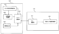
- the front right acceleration sensor 600 includes a sensor communication unit 601, a sensor ID recording unit 602, and an impact detection unit 603.
- the Sensor communication unit 601 communicates with airbag ECU 100.
- the sensor ID recording unit 602 is a memory in which identification data (individual identification ID) for identifying an individual of the front right acceleration sensor 600 is recorded, and is configured by a nonvolatile memory.
- the identification data (individual identification ID) is data that can uniquely identify an external sensor.
- the identification data is written as unique data on the production line when the external sensor is produced.
- the impact (acceleration) detection unit 603 is a sensor that detects data (acceleration or impact value) used to determine whether to activate a protective device such as an airbag.
- the airbag ECU 100 includes an ECU communication unit 181, a defective sensor attachment determination unit 182, a first sensor failure diagnosis unit 183-1, a defective sensor ID recording unit 184, and an equipment sensor ID recording unit 185. Prepare.
- the ECU communication unit 181 communicates with the front right acceleration sensor 600.
- the ECU communication unit 181 is realized by, for example, the SPI 134 and the sensor I / F 144, but is not limited thereto.
- the ECU communication unit 181 receives the sensing data detected by the impact detection unit 603 and the identification data recorded in the sensor ID recording unit 602 from the sensor communication unit 601.
- the defective sensor mounting determination unit 182 determines that a defective sensor that has been diagnosed in the past is stored in the airbag ECU 100 based on failure history data that indicates whether or not the external sensor has been diagnosed in the past. It is determined whether or not it is connected.
- the defective sensor attachment determination unit 182 is realized by the CPU 122, for example, but is not limited thereto.
- the first sensor failure diagnosis unit 183-1 diagnoses whether or not an external sensor (an external sensor currently connected to the airbag ECU 100) has failed based on the received sensing data.
- the first sensor failure diagnosing unit 183-1 may, for example, fix the sensing data detected by the impact detection unit 603 to a high value outside the normal range for a predetermined period, or to fix a low value outside the normal range for a predetermined period. If the abnormal value continues for a predetermined time, such as, the front right acceleration sensor 600 is diagnosed as being broken.
- the first sensor failure diagnosis unit 183-1 is realized by the CPU 122, for example, but is not limited thereto.
- the defective sensor ID recording unit 184 is a memory for recording the identification data of the external sensor diagnosed as having failed by the first sensor failure diagnosing unit 183-1 as failure history data.
- the defective sensor ID recording unit 184 is realized by the nonvolatile memory 160.
- the equipment sensor ID recording unit 185 is a memory for recording identification data of an external sensor (equipment sensor) currently connected to the airbag ECU 100.
- the equipment sensor ID recording unit 185 is realized by the RAM 126, for example, but is not limited thereto.
- the defective sensor attachment determination unit 182 includes identification data (identification data of an external sensor that has been diagnosed as a failure in the past) recorded in the defective sensor ID recording unit 184, and an equipment sensor ID record received by the ECU communication unit 181. It is determined whether or not the defective sensor is connected to the airbag ECU 100 by comparing the identification data recorded in the unit 185 (identification data of the external sensor currently connected to the airbag ECU 100). Specifically, the defective sensor attachment determination unit 182 determines that the defective sensor is not detected when the identification data recorded in the equipment sensor ID recording unit 185 matches any of the identification data recorded in the defective sensor ID recording unit 184. Is determined to be connected to the airbag ECU 100. If they do not match, it is determined that the defective sensor is not connected to the airbag ECU 100.
- FIG. 3 is a flowchart of the airbag control system (airbag ECU and external sensor) of the first embodiment.
- FIG. 3A is an overall flowchart of the airbag control system of the first embodiment
- FIG. 3B is a flowchart relating to initial processing of the airbag control system of the first embodiment
- FIG. 3B is a flowchart of the first embodiment. It is a flowchart regarding the normal processing of the airbag control system.
- the airbag control system 1000 first performs initial processing (step S100), for example, when a vehicle ignition switch is turned on, and then repeatedly performs normal processing (step S200).
- the sensor communication unit 601 transmits the individual identification ID of the front right acceleration sensor 600 recorded in the sensor ID recording unit 602 to the airbag ECU 100 (step S101). Note that if the data cannot be transmitted from the sensor communication unit 601 to the airbag ECU 100 at one time because the data length of the individual identification ID is long, the data may be divided into a plurality of times and transmitted. The individual identification ID is not necessary for the normal operation of the airbag ECU 100, and it is sufficient that the airbag ECU 100 can receive the IGN power supply once when it is activated. Is desirable.
- the ECU communication unit 181 receives the individual identification ID (step S102). Subsequently, the ECU communication unit 181 writes the received individual identification ID as an equipment sensor in the equipment sensor ID recording unit 185 (step S103).
- the defective sensor attachment determination unit 182 determines whether or not the same individual identification ID as that of the equipment sensor is recorded in the defective sensor ID recording unit 184 (step S104). If the same individual identification ID as that of the equipment sensor is not recorded in the defective sensor ID recording unit 184 (No in step S104), the defective sensor attachment determination unit 182 ends the process.
- the defective sensor attachment determination unit 182 is connected to the airbag ECU 100. That is, it is determined that the defective sensor installed in the airbag ECU 100 has not been replaced (step S105), and the process is terminated. If the defective sensor mounting determination unit 182 determines that the defective sensor installed in the airbag ECU 100 has not been replaced, the airbag warning lamp 800 outputs an alarm to that effect or the function of the airbag ECU 100. Can be stopped.
- step S200 the sensor communication unit 601 transmits the impact value detected by the impact detection unit 603 to the airbag ECU 100 (step S201).
- the ECU communication unit 181 receives the impact value (step S202). Subsequently, the first sensor failure diagnosis unit 183-1 determines whether or not the impact value received by the ECU communication unit 181 is outside the normal range and continues for a predetermined time (step S203).
- the first sensor failure diagnosis unit 183-1 ends the process when the impact value received by the ECU communication unit 181 is not outside the normal range or has not continued for a predetermined time (step S203, No). To do.
- step S203 when the impact value received by the ECU communication unit 181 is outside the normal range and continues for a predetermined time (step S203, Yes), the first sensor failure diagnosis unit 183-1 It is determined that the sensor is a defective sensor (step S204).
- the first sensor failure diagnosis unit 183-1 monitors the impact value received from the external sensor and diagnoses whether the external sensor is normal. Specifically, the first sensor failure diagnosing unit 183-1 determines that if the received impact value is a high value outside the normal range or a low value outside the normal range and continues for a predetermined time or longer, the first sensor failure diagnosis unit 183-1 It is determined that the sensor is defective because an abnormality has occurred. It is desirable that the time required to determine that there is a failure is longer than the time during which the impact value changes due to a vehicle collision. In addition, the time required to determine the normal range of the impact value or the failure is set to an appropriate value according to the reliability required of the airbag ECU 100 and the reliability of the components to be employed.
- the first sensor failure diagnosis unit 183-1 records the individual identification ID of the equipment sensor in the defective sensor ID recording unit 184 (step S205), and ends the process. Note that, when the ECU communication unit 181 receives the impact value, processing such as determination as to whether or not to deploy the airbag is performed based on the received impact value, but detailed description of this point is omitted.
- the individual identification ID of the external sensor diagnosed as malfunctioning is recorded in the defective sensor ID recording unit 184, the individual identification of the external sensor currently connected to the airbag ECU 100 is performed. By collating with the ID, it is possible to determine whether or not a defective sensor that has been diagnosed as having failed in the past is connected to the airbag ECU 100.
- FIG. 4 is a diagram illustrating functional blocks of an airbag control system (an airbag ECU and an external sensor) according to the second embodiment. Detailed description of the same configuration as that of the first embodiment is omitted.
- the front right acceleration sensor 600 includes a sensor communication unit 601, a sensor ID recording unit 602, an impact detection unit 603, and a sensor internal failure diagnosis unit 604.
- the sensor internal failure diagnosis unit 604 diagnoses whether or not the front right acceleration sensor 600 has failed. For example, the sensor internal failure diagnosis unit 604 physically operates the elements of the sensing part of the impact detection unit 603 on the + side and the ⁇ side, respectively, and determines whether or not the impact value normally exceeds a predetermined threshold value. If the impact value does not exceed the predetermined threshold, the sensor internal failure diagnosis unit 604 determines that any failure has occurred in the external sensor and determines that it is a defective sensor. On the other hand, if the impact value exceeds a predetermined threshold, the sensor internal failure diagnosis unit 604 determines that the external sensor is normal.
- the airbag ECU 100 includes an ECU communication unit 181, a defective sensor attachment determination unit 182, a defective sensor ID recording unit 184, an equipment sensor ID recording unit 185, and a second sensor failure diagnosis unit 183-2.
- the ECU communication unit 181 records the diagnosis result (for example, failure information indicating that the external sensor is defective) diagnosed by the sensor internal failure diagnosis unit 604 and the sensor ID recording unit 602 from the sensor communication unit 601. Receive identification data.
- the ECU communication unit 181 also receives sensing data detected by the impact detection unit 603.
- the second sensor failure diagnosis unit 183-2 diagnoses whether or not the front right acceleration sensor 600 has failed based on the diagnosis result transmitted from the front right acceleration sensor 600.
- the defective sensor ID recording unit 184 records the identification data of the external sensor diagnosed as having failed by the second sensor failure diagnosing unit 183-2 as failure history data.
- the defective sensor attachment determination unit 182 includes identification data (identification data of an external sensor that has been diagnosed as a failure in the past) recorded in the defective sensor ID recording unit 184, and an equipment sensor ID record received by the ECU communication unit 181. It is determined whether or not the defective sensor is connected to the airbag ECU 100 by comparing the identification data recorded in the unit 185 (identification data of the external sensor currently connected to the airbag ECU 100). Specifically, the defective sensor attachment determination unit 182 determines that the defective sensor is not detected when the identification data recorded in the equipment sensor ID recording unit 185 matches any of the identification data recorded in the defective sensor ID recording unit 184. Is determined to be connected to the airbag ECU 100. If they do not match, it is determined that the defective sensor is not connected to the airbag ECU 100.
- FIG. 5 is a flowchart of the airbag control system (airbag ECU and external sensor) of the second embodiment.
- the overall flowchart of the airbag control system 1000 of the second embodiment is the same as that of the first embodiment (FIG. 3A).
- the flowchart regarding the initial process of the airbag control system of 2nd Embodiment is the same as that of 1st Embodiment (FIG. 3B). Therefore, only the flowchart regarding the normal process of the airbag control system of 2nd Embodiment is demonstrated.
- the sensor internal failure diagnosis unit 604 performs internal failure diagnosis (step S211). Subsequently, the sensor internal failure diagnosis unit 604 determines whether or not the result of the internal failure diagnosis is a failure (step S212).
- the sensor communication unit 601 transmits failure information indicating that the external sensor is failed to the airbag ECU 100 (step S213).
- the sensor communication unit 601 transmits the impact value detected by the impact detection unit 603 to the airbag ECU 100 (step S214).
- the second sensor failure diagnosis unit 183-2 determines whether the data received from the external sensor is failure information (step S215). If the data received from the external sensor is not failure information (No in step S215), the second sensor failure diagnosis unit 183-2 ends the process.
- the second sensor failure diagnosis unit 183-2 records the individual identification ID of the equipment sensor in the defective sensor ID recording unit 184. (Step S216), and the process is terminated.
- the individual identification ID of the external sensor diagnosed as having failed by the external sensor is recorded in the defective sensor ID recording unit 184, and the external sensor currently connected to the airbag ECU 100 is recorded.
- the individual identification ID it is possible to determine whether or not a defective sensor that has been diagnosed as having failed in the past is connected to the airbag ECU 100.
- FIG. 6 is a diagram showing functional blocks of the airbag control system (airbag ECU and external sensor) of the third embodiment. Detailed description of the same configuration as that of the first or second embodiment is omitted.
- the front right acceleration sensor 600 includes a sensor communication unit 601, an impact detection unit 603, and a failure history recording unit 605.
- the failure history recording unit 605 is a memory for recording the failure history data of the failure history recording unit 605, and is configured by a nonvolatile memory.
- the airbag ECU 100 includes an ECU communication unit 181, a defective sensor attachment determination unit 182, a first sensor failure diagnosis unit 183-1, and a write request unit 186.
- the ECU communication unit 181 receives sensing data detected by the impact detection unit 603 from the sensor communication unit 601.
- the write request unit 186 is provided in the front right acceleration sensor 600 diagnosed as being defective when the first sensor failure diagnosis unit 183-1 diagnoses that the front right acceleration sensor 600 is defective.
- the failure history recording unit 605 outputs a request for recording failure information as failure history data. As a result, failure information is recorded in the failure history recording unit 605.
- the ECU communication unit 181 receives failure information recorded in the failure history recording unit 605 from the sensor communication unit 601.
- the defective sensor attachment determining unit 182 determines whether or not the defective sensor is connected to the airbag ECU 100 based on the failure information received by the ECU communication unit 181. For example, if the failure information is included in the data transmitted from the external sensor currently connected to the airbag ECU 100, the defective sensor attachment determination unit 182 determines that the defective sensor is connected to the airbag ECU 100. To do. On the other hand, if the failure sensor is not included in the data transmitted from the external sensor currently connected to the airbag ECU 100, the failure sensor attachment determination unit 182 indicates that the failure sensor is not connected to the airbag ECU 100. judge.
- FIG. 7 is a flowchart of the airbag control system (airbag ECU and external sensor) of the third embodiment.
- the overall flowchart of the airbag control system 1000 of the third embodiment is the same as that of the first embodiment (FIG. 3A). Therefore, only the flowchart regarding the initial process of the airbag control system of the third embodiment and the flowchart regarding the normal process of the airbag control system of the third embodiment will be described.
- FIG. 7A is a flowchart regarding an initial process of the airbag control system of the third embodiment
- FIG. 7B is a flowchart regarding a normal process of the airbag control system of the third embodiment.
- the sensor communication unit 601 determines whether or not the failure history recording unit 605 has a failure history (failure information write history) of the front right acceleration sensor 600 (step S121).
- the sensor communication unit 601 transmits a signal (failure information) indicating that there is an internal failure to the airbag ECU 100 (step S121). S122).
- the sensor communication unit 601 transmits a signal indicating no internal failure to the airbag ECU 100 (step S123).
- the defective sensor attachment determination unit 182 determines whether or not the received data from the external sensor is a signal (failure information) indicating that there is an internal failure (step S124).
- the defective sensor attachment determination unit 182 ends the process.
- the defective sensor attachment determination unit 182 indicates that the defective sensor is connected to the airbag ECU 100. That is, it is determined that the defective sensor installed in the airbag ECU 100 has not been replaced (step S125), and the process ends. If the defective sensor mounting determination unit 182 determines that the defective sensor installed in the airbag ECU 100 has not been replaced, the airbag warning lamp 800 outputs an alarm to that effect or the function of the airbag ECU 100. Can be stopped.
- step S200 the sensor communication unit 601 transmits the impact value detected by the impact detection unit 603 to the airbag ECU 100 (step S221).
- the ECU communication unit 181 receives the impact value (step S222). Subsequently, the first sensor failure diagnosis unit 183-1 determines whether or not the impact value received by the ECU communication unit 181 is outside the normal range and continues for a predetermined time (step S223).
- the first sensor failure diagnosis unit 183-1 ends the process when the impact value received by the ECU communication unit 181 is not outside the normal range or has not continued for a predetermined time (step S223, No). To do.
- step S224 when the impact value received by the ECU communication unit 181 is outside the normal range and continues for a predetermined time (step S223, Yes), the first sensor failure diagnosis unit 183-1 It is determined that the sensor is a defective sensor (step S224).
- the write request unit 186 transmits failure information to the external sensor diagnosed as having failed (step S225), and requests the failure history recording unit 605 to record the failure information.
- the sensor communication unit 601 receives the failure information transmitted from the write request unit 186, records the received failure information in the failure history recording unit 605 (step S226), and ends the process.
- the airbag ECU 100 diagnoses the presence / absence of a failure in the external sensor, and records the failure information in the external sensor when there is a failure. It is held in the recording unit 605. Then, since the external sensor transmits failure history data to the airbag ECU 100 in the initial process, the airbag ECU 100 detects that a failure sensor that has been diagnosed as having failed in the past is based on the failure history data. It can be determined whether or not it is connected to the bag ECU 100. According to the third embodiment, since the external sensor holds its own failure history data in its own failure history recording unit 605, the defective sensor is removed from the vehicle and replaced with a non-defective product on the vehicle assembly line or the like. Then, even if the defective sensor is mistakenly assembled to another vehicle without being discarded, it is possible to further obtain an effect that it is possible to detect that the defective sensor is attached.
- FIG. 8 is a diagram illustrating functional blocks of an airbag control system (an airbag ECU and an external sensor) according to a fourth embodiment. Detailed description of the same configuration as in the first to third embodiments is omitted.
- the front right acceleration sensor 600 includes a sensor communication unit 601, an impact detection unit 603, a sensor internal failure diagnosis unit 604, and a failure history recording unit 605.
- the airbag ECU 100 includes an ECU communication unit 181, a defective sensor attachment determination unit 182, a second sensor failure diagnosis unit 183-2, and a write request unit 186.
- the ECU communication unit 181 receives from the sensor communication unit 601 a diagnosis result (diagnosis result diagnosed by the sensor internal failure diagnosis unit 604) that diagnoses whether or not the front right acceleration sensor 600 has failed.
- the ECU communication unit 181 also receives sensing data detected by the impact detection unit 603.
- the second sensor failure diagnosis unit 183-2 diagnoses whether or not the front right acceleration sensor 600 has failed based on the diagnosis result transmitted from the front right acceleration sensor 600.
- the write request unit 186 is provided in the front right acceleration sensor 600 diagnosed as malfunctioning when the second sensor malfunction diagnosis unit 183-2 diagnoses that the front right acceleration sensor 600 is malfunctioning.
- the failure history recording unit 605 outputs a request for recording failure information as failure history data. As a result, failure information is recorded in the failure history recording unit 605.
- the ECU communication unit 181 receives failure information recorded in the failure history recording unit 605 from the sensor communication unit 601.
- the defective sensor attachment determining unit 182 determines whether or not the defective sensor is connected to the airbag ECU 100 based on the failure information received by the ECU communication unit 181. For example, if the failure information is included in the data transmitted from the external sensor currently connected to the airbag ECU 100, the defective sensor attachment determination unit 182 determines that the defective sensor is connected to the airbag ECU 100. To do. On the other hand, if the failure sensor is not included in the data transmitted from the external sensor currently connected to the airbag ECU 100, the failure sensor attachment determination unit 182 indicates that the failure sensor is not connected to the airbag ECU 100. judge.
- FIG. 9 is a flowchart of the airbag control system (airbag ECU and external sensor) of the fourth embodiment.
- the overall flowchart of the airbag control system 1000 of the fourth embodiment is the same as that of the first embodiment (FIG. 3A).
- the flowchart of the initial process of the airbag control system 1000 of 4th Embodiment is the same as that of 3rd Embodiment (FIG. 7A). Therefore, only the flowchart regarding the normal process of the airbag control system of the fourth embodiment will be described.
- the sensor internal failure diagnosis unit 604 performs internal failure diagnosis (step S231). Subsequently, the sensor internal failure diagnosis unit 604 determines whether or not the result of the internal failure diagnosis is a failure (step S232).
- the sensor communication unit 601 determines that the result of the internal failure diagnosis is a failure (step S232, Yes)
- the sensor communication unit 601 transmits failure information indicating that the external sensor is failed to the airbag ECU 100 (step S233).
- the sensor communication unit 601 transmits the impact value detected by the impact detection unit 603 to the airbag ECU 100 (step S234).
- the second sensor failure diagnosis unit 183-2 determines whether or not the data received from the external sensor is failure information (step S235). If the data received from the external sensor is not failure information (step S235, No), the second sensor failure diagnosis unit 183-2 ends the process.
- the second sensor failure diagnosis unit 183-2 determines that the equipment sensor is a defective sensor (step S236).
- the write request unit 186 transmits failure information to the external sensor diagnosed as having failed (step S237), and requests the failure history recording unit 605 to record the failure information.
- the sensor communication unit 601 receives the failure information transmitted from the write request unit 186, records the received failure information in the failure history recording unit 605 (step S238), and ends the process.
- the external sensor itself diagnoses the presence or absence of a failure of the external sensor. If there is a failure, the failure information is recorded in the external sensor in response to a write request from the airbag ECU 100. Holds its own failure history data in the failure history recording unit 605. Then, since the external sensor transmits the failure history data to the airbag ECU 100 in the initial process, the airbag ECU 100 detects that the failure sensor that has been diagnosed as a failure in the past is based on the failure history data. It can be determined whether or not the ECU 100 is connected.
- FIG. 10 is a diagram illustrating functional blocks of an airbag control system (an airbag ECU and an external sensor) according to a fifth embodiment. Detailed description of the same configuration as in the first to fourth embodiments is omitted.
- the front right acceleration sensor 600 includes a sensor communication unit 601, an impact detection unit 603, a sensor internal failure diagnosis unit 604, and a failure history recording unit 605.
- the sensor internal failure diagnosis unit 604 diagnoses whether or not the front right acceleration sensor 600 has failed. For example, the sensor internal failure diagnosis unit 604 physically operates the elements of the sensing part of the impact detection unit 603 on the + side and the ⁇ side, respectively, and determines whether or not the impact value normally exceeds a predetermined threshold value. If the impact value does not exceed the predetermined threshold, the sensor internal failure diagnosis unit 604 determines that any failure has occurred in the external sensor and determines that it is a defective sensor. On the other hand, if the impact value exceeds a predetermined threshold, the sensor internal failure diagnosis unit 604 determines that the external sensor is normal. Furthermore, if the sensor internal failure diagnosis unit 604 diagnoses that the front right acceleration sensor 600 is defective, it records failure information as failure history data in the failure history recording unit 605.
- the airbag ECU 100 includes an ECU communication unit 181 and a defective sensor attachment determination unit 182.
- ECU communication unit 181 receives failure history data recorded in failure history recording unit 605 from sensor communication unit 601.
- Defective sensor wearing determination unit 182 determines whether or not a defective sensor is connected to airbag ECU 100 based on the failure history data received by ECU communication unit 181. For example, if the failure sensor data is included in failure history data transmitted from an external sensor currently connected to the airbag ECU 100, the failure sensor attachment determination unit 182 is connected to the airbag ECU 100. Is determined. On the other hand, if the failure sensor data is not included in the failure history data transmitted from the external sensor currently connected to the airbag ECU 100, the failure sensor attachment determination unit 182 indicates that the failure sensor is connected to the airbag ECU 100. Judge that there is no.
- FIG. 11 is a flowchart of the airbag control system (airbag ECU and external sensor) of the fifth embodiment.
- the overall flowchart of the airbag control system 1000 of the fifth embodiment is the same as that of the first embodiment (FIG. 3A).
- the flowchart regarding the initial process of the airbag control system of 5th Embodiment is the same as that of 3rd Embodiment (FIG. 7A). Therefore, only the flowchart regarding the normal process of the airbag control system of the fifth embodiment will be described.
- the sensor internal failure diagnosis unit 604 performs internal failure diagnosis (step S241). Subsequently, the sensor internal failure diagnosis unit 604 determines whether or not the result of the internal failure diagnosis is a failure (step S242).
- the sensor internal failure diagnosis unit 604 When it is determined that the result of the internal failure diagnosis is a failure (step S242, Yes), the sensor internal failure diagnosis unit 604 records failure information in the failure history recording unit 605 (step S243). Subsequently, the sensor communication unit 601 transmits failure information indicating that the external sensor is in failure to the airbag ECU 100 (step S244).
- the sensor communication unit 601 transmits the impact value detected by the impact detection unit 603 to the airbag ECU 100 (step S245).
- step S244 or step S245 the defective sensor attachment determination unit 182 determines whether or not the data received from the external sensor is failure information (step S246). If the data received from the external sensor is not failure information (No in step S246), the defective sensor attachment determination unit 182 ends the process.
- step S246 if the data received from the external sensor is failure information (Yes in step S246), the defective sensor attachment determination unit 182 is the defective sensor, and the defective sensor is connected to the airbag ECU 100. Is determined (step S247), and the process is terminated.
- the external sensor itself diagnoses the presence or absence of a failure of the external sensor, and the diagnosis result is recorded in the failure history recording unit 605. Since the external sensor transmits the failure history data to the airbag ECU 100, the airbag ECU 100 is connected to the airbag ECU 100 with a defective sensor that has been diagnosed as having failed in the past based on the failure history data. It can be determined whether or not.
- FIG. 12 is a diagram illustrating functional blocks of an airbag control system (an airbag ECU, an external sensor, and a failure diagnosis device) according to a sixth embodiment. Detailed description of the same configuration as in the first to fifth embodiments is omitted.
- the front right acceleration sensor 600 includes a sensor communication unit 601, a sensor ID recording unit 602, and an impact detection unit 603.
- the airbag ECU 100 includes an ECU communication unit 181, a defective sensor mounting determination unit 182, a first sensor failure diagnosis unit 183-1, a defective sensor ID recording unit 184, an equipment sensor ID recording unit 185, an ECU A second communication unit 187.
- the ECU second communication unit 187 communicates with the failure diagnosis apparatus (diagnostic tester) 700.
- the ECU second communication unit 187 is realized by, for example, the CAN communication controller 128, but is not limited thereto.
- the failure diagnosis apparatus 700 includes a failure diagnosis apparatus communication unit 710, an equipment sensor ID reading unit 720, a defective sensor ID reading unit 730, and a display unit 740.
- the failure diagnosis device communication unit 710 communicates with the airbag ECU 100.
- the equipment sensor ID reading unit 720 reads identification data (individual identification ID) for identifying an individual external sensor currently connected to the airbag ECU 100 via the fault diagnosis device communication unit 710.
- the defective sensor ID reading unit 730 reads identification data for identifying an individual defective sensor via the failure diagnosis device communication unit 710.
- the display unit 740 reads the individual identification ID of the external sensor currently connected to the airbag ECU 100 read by the equipment sensor ID reading unit 720 and the individual identification of the defective sensor read by the defective sensor ID reading unit 730. This is an output interface that displays an ID.
- FIG. 13 is a flowchart of the airbag control system (airbag ECU, external sensor, and failure diagnosis device) of the sixth embodiment.
- FIG. 13A is an overall flowchart of the airbag control system according to the sixth embodiment
- FIG. 13B is a flowchart related to the failure diagnosis apparatus communication process of the airbag control system according to the sixth embodiment.
- the flowchart regarding the initial process of the airbag control system of the sixth embodiment is the same as that of the first embodiment (FIG. 3B). Moreover, the flowchart regarding the normal process of the airbag control system of 6th Embodiment is the same as that of 1st Embodiment (FIG. 3C). Therefore, only the overall flowchart of the airbag control system of the sixth embodiment and the flowchart relating to the failure diagnosis apparatus communication process will be described.
- the airbag control system 1000 first performs an initial process, for example, when the ignition switch of the vehicle is turned on (step S100). Subsequently, the airbag control system 1000 performs normal processing (step S200), and then performs failure diagnosis device communication processing (step S300). The airbag control system 1000 repeats the normal process (step S200) and the failure diagnosis apparatus communication process (step S300).
- the ECU second communication unit 187 determines whether or not the failure diagnosis apparatus 700 is connected (step S301). If the failure diagnosis apparatus 700 is not connected (No at Step S301), the ECU second communication unit 187 ends the process.
- the equipment sensor ID reading unit 720 sets the individual identification ID of the currently connected sensor to the air via the failure diagnosis device communication unit 710. Request is made to the bag ECU 100 (step S302).
- the ECU second communication unit 187 reads the individual identification ID of the currently connected sensor from the equipment sensor ID recording unit 185 and transmits it to the failure diagnosis apparatus 700 (step S303).
- the display unit 740 displays the individual identification ID of the currently connected sensor read by the equipment sensor ID reading unit 720 (step S304).
- the defective sensor ID reading unit 730 requests the airbag ECU 100 to check whether or not the defective sensor is connected (step S305).
- the defective sensor attachment determination unit 182 transmits the presence / absence of connection of the defective sensor to the failure diagnosis apparatus 700 via the ECU second communication unit 187 (step S306).
- the defective sensor ID reading unit 730 determines whether or not the defective sensor is connected based on the signal indicating whether or not the defective sensor is connected, transmitted from the defective sensor mounting determination unit 182 (step S307). If the defective sensor ID reading unit 730 determines that the defective sensor is not connected (No in step S307), the process is terminated.
- the defective sensor ID reading unit 730 requests the airbag ECU for the identification ID of the defective sensor (step S308).
- the defective sensor attachment determination unit 182 transmits the individual identification ID of the defective sensor to the failure diagnosis apparatus 700 via the ECU second communication unit 187 (step S309).
- the display unit 740 displays the individual identification ID of the defective sensor read by the defective sensor ID reading unit 730 (step S310).
- the individual identification ID of the external sensor connected to the airbag ECU 100 can be read from the failure diagnosis device 700 via the vehicle communication network. Further, the individual identification ID of the external sensor held by the airbag ECU 100, the presence / absence of the sensor determined to have a failure of the external sensor in the past, and the individual identification ID can be read from the failure diagnosis apparatus 700 by communication.
- the sixth embodiment it is possible to identify the individual external sensor currently assembled in the vehicle on the vehicle assembly line. Therefore, conventionally, traceability between the vehicle and the external sensor has been ensured by reading the barcode label attached to the external sensor with a barcode reader, but the work of reading with the barcode reader in the vehicle assembly line can be abolished. As a result, the time for assembling the vehicle can be shortened. Further, since the barcode label to be attached to the external sensor is not necessary, the cost of the barcode label itself can be reduced. In addition, the time required for manufacturing the external sensor can be shortened by eliminating the need to attach a barcode when manufacturing the external sensor. Moreover, since it is possible to identify an individual external sensor that has been determined to have failed in the past in the vehicle assembly line, it is possible to reliably prevent defective products from flowing into the market.
- FIG. 14 is a diagram illustrating functional blocks of an airbag control system (an airbag ECU, an external sensor, and a failure diagnosis device) according to a seventh embodiment. Detailed descriptions of the same configurations as those of the first to sixth embodiments are omitted.
- the front right acceleration sensor 600 includes a sensor communication unit 601, a sensor ID recording unit 602, an impact detection unit 603, and a sensor internal failure diagnosis unit 604.
- the airbag ECU 100 includes an ECU communication unit 181, a defective sensor attachment determination unit 182, a second sensor failure diagnosis unit 183-2, a defective sensor ID recording unit 184, an equipment sensor ID recording unit 185, an ECU A second communication unit 187.
- the failure diagnosis device 700 includes a failure diagnosis device communication unit 710, an equipment sensor ID reading unit 720, a defective sensor ID reading unit 730, and a display unit 740.
- the overall flowchart of the airbag control system of the seventh embodiment is the same as that of the sixth embodiment (FIG. 13A). Moreover, the flowchart regarding the initial process of the airbag control system of 7th Embodiment is the same as that of 1st Embodiment (FIG. 3B). Moreover, the flowchart regarding the normal process of the airbag control system of 7th Embodiment is the same as that of 2nd Embodiment (FIG. 5). Moreover, the flowchart regarding the failure diagnosis communication process of the airbag control system of 7th Embodiment is the same as that of 6th Embodiment (FIG. 13B).
- the individual identification ID of the external sensor connected to the airbag ECU 100 can be read from the failure diagnosis apparatus 700 via the vehicle communication network. Further, the individual identification ID of the external sensor held by the airbag ECU 100, the presence / absence of the sensor determined to have a failure of the external sensor in the past, and the individual identification ID can be read from the failure diagnosis apparatus 700 by communication.
- the individual external sensor currently assembled in the vehicle can be identified on the vehicle assembly line. Therefore, conventionally, traceability between the vehicle and the external sensor has been ensured by reading the barcode label attached to the external sensor with a barcode reader, but the work of reading with the barcode reader in the vehicle assembly line can be abolished. As a result, the time for assembling the vehicle can be shortened. Further, since the barcode label to be attached to the external sensor is not necessary, the cost of the barcode label itself can be reduced. In addition, the time required for manufacturing the external sensor can be shortened by eliminating the need to attach a barcode when manufacturing the external sensor. Moreover, since it is possible to identify an individual external sensor that has been determined to have failed in the past in the vehicle assembly line, it is possible to reliably prevent defective products from flowing into the market.
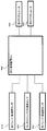
- FIG. 15 is a diagram showing functional blocks of a control system for protecting pedestrians.
- the pedestrian protection control system includes a pedestrian protection ECU 900, a right bumper acceleration sensor 910, a center bumper acceleration sensor 920, a left bumper acceleration sensor 930, and a first actuator 940.
- a second actuator 950 is a diagram showing functional blocks of a control system for protecting pedestrians.
- the pedestrian protection control system includes a pedestrian protection ECU 900, a right bumper acceleration sensor 910, a center bumper acceleration sensor 920, a left bumper acceleration sensor 930, and a first actuator 940.
- a second actuator 950 is a diagram showing functional blocks of a control system for protecting pedestrians.
- the pedestrian protection control system includes a pedestrian protection ECU 900, a right bumper acceleration sensor 910, a center bumper acceleration sensor 920, a left bumper acceleration sensor 930, and a first actuator 940.
- a second actuator 950 is a third actuator 950.
- the right bumper acceleration sensor 910, the center bumper acceleration sensor 920, and the left bumper acceleration sensor 930 acquire the acceleration when the vehicle collides with a pedestrian, and transmits it to the pedestrian protection ECU 900.
- the pedestrian protection ECU 900 estimates the collision object based on data received from the right bumper acceleration sensor 910, the center bumper acceleration sensor 920, and the left bumper acceleration sensor 930, and determines that the pedestrian is a pedestrian. 940, the second actuator 950 is operated.
- the pedestrian protection ECU 900 increases the clearance (interval) between the hood and the engine directly below the hood by lifting the hood with the first actuator 940 and the second actuator 950, for example, in a vehicle having a small hood and engine clearance. By lowering the pedestrian obstacle value.
- the pedestrian protection ECU 900 is, for example, an airbag that deploys the wiper and the A pillar to the outside in order to prevent the obstacle value from increasing due to the collision of the pedestrian with the protrusion or the A pillar at the base of the wiper. It also has a covering function.
- the pedestrian protection ECU 900 activates the first actuator 940 and the second actuator 950 by, for example, energizing the squib to ignite the inflator to generate gas, and to operate the piston with the generated gas.
- the airbag ECU 100 and the pedestrian protection ECU 900 can be integrated.
Landscapes
- Physics & Mathematics (AREA)
- General Physics & Mathematics (AREA)
- Engineering & Computer Science (AREA)
- Mechanical Engineering (AREA)
- Air Bags (AREA)
- Testing And Monitoring For Control Systems (AREA)
- Arrangements For Transmission Of Measured Signals (AREA)
Abstract
Description
Read Only Memory)である。不揮発メモリ160は、例えば、SPI138を介してMCU120から出力されたデータを記録する。
次に、第1実施形態の外部センサ及びエアバッグECUの機能ブロックについて説明する。図2は、第1実施形態のエアバッグ制御システム(エアバッグECU及び外部センサ)の機能ブロックを示す図である。以下の各実施形態では、外部センサの一例としてフロント右加速度センサ600を挙げて説明するが、他の外部センサ(フロント左加速度センサ610、右サイド加速度センサ620、左サイド加速度センサ630、右サイド圧力センサ640、及び左サイド圧力センサ650)も同様の構成であり、複数の外部センサがエアバッグECU100に接続されるものとする。なお、外部センサのエアバッグECU100への接続方式は特に限定されず、ピアツーピア方式、バス接続(パラレル接続、デイジーチェーン接続)等に適用可能である。
次に、第2実施形態の外部センサ及びエアバッグECUの機能ブロックについて説明する。図4は、第2実施形態のエアバッグ制御システム(エアバッグECU及び外部センサ)の機能ブロックを示す図である。第1実施形態と同一の構成については詳細な説明を省略する。
次に、第3実施形態の外部センサ及びエアバッグECUの機能ブロックについて説明する。図6は、第3実施形態のエアバッグ制御システム(エアバッグECU及び外部センサ)の機能ブロックを示す図である。第1又は第2実施形態と同一の構成については詳細な説明を省略する。
次に、第4実施形態の外部センサ及びエアバッグECUの機能ブロックについて説明する。図8は、第4実施形態のエアバッグ制御システム(エアバッグECU及び外部センサ)の機能ブロックを示す図である。第1~3実施形態と同一の構成については詳細な説明を省略する。
次に、第5実施形態の外部センサ及びエアバッグECUの機能ブロックについて説明する。図10は、第5実施形態のエアバッグ制御システム(エアバッグECU及び外部センサ)の機能ブロックを示す図である。第1~4実施形態と同一の構成については詳細な説明を省略する。
次に、第6実施形態の外部センサ、エアバッグECU、及び故障診断装置の機能ブロックについて説明する。図12は、第6実施形態のエアバッグ制御システム(エアバッグECU、外部センサ、及び故障診断装置)の機能ブロックを示す図である。第1~5実施形態と同一の構成については詳細な説明を省略する。
次に、第7実施形態の外部センサ、エアバッグECU、及び故障診断装置の機能ブロックについて説明する。図14は、第7実施形態のエアバッグ制御システム(エアバッグECU、外部センサ、及び故障診断装置)の機能ブロックを示す図である。第1~6実施形態と同一の構成については詳細な説明を省略する。
Claims (18)
- 車両の乗員又は歩行者を保護するための保護装置を制御する制御装置であって、
前記制御装置に接続される外部センサとの間で通信を行う通信部と、
前記外部センサが過去に故障と診断されたことがあるか否かを示す故障履歴データに基づいて、過去に故障と診断されたことがある不良センサが前記制御装置に接続されているか否かを判定する判定部と、
を備えることを特徴とする制御装置。 - 請求項1の制御装置において、
前記判定部は、前記制御装置に接続されている外部センサの個体を識別するための識別データと、過去に故障と診断されたことがある不良センサの個体を識別するための識別データとを比較することによって、前記不良センサが前記制御装置に接続されているか否かを判定する、
ことを特徴とする制御装置。 - 請求項2の制御装置において、
前記通信部は、前記外部センサから、該外部センサによって検出されたセンシングデータ、及び該外部センサの個体を識別するための識別データを受信し、
前記制御装置は、
前記センシングデータに基づいて前記外部センサが故障しているか否かを診断するセンサ故障診断部と、
前記センサ故障診断部によって故障していると診断された外部センサの前記識別データを前記故障履歴データとして記録する不良センサID記録部と、をさらに備え、
前記判定部は、前記不良センサID記録部に記録された前記識別データと、前記通信部によって受信された前記識別データとを比較することによって、前記不良センサが前記制御装置に接続されているか否かを判定する、
ことを特徴とする制御装置。 - 請求項2の制御装置において、
前記通信部は、前記外部センサから、前記外部センサが故障しているか否かを診断した診断結果、及び該外部センサの個体を識別するための識別データを受信し、
前記制御装置は、
前記外部センサから送信された前記診断結果に基づいて前記外部センサが故障しているか否かを診断するセンサ故障診断部と、
前記センサ故障診断部によって故障していると診断された外部センサの前記識別データを前記故障履歴データとして記録する不良センサID記録部と、をさらに備え、
前記判定部は、前記不良センサID記録部に記録された前記識別データと、前記通信部によって受信された前記識別データとを比較することによって、前記不良センサが前記制御装置に接続されているか否かを判定する、
ことを特徴とする制御装置。 - 請求項1の制御装置において、
前記判定部は、前記外部センサに設けられた故障履歴記録部に記録された故障履歴データに基づいて、前記不良センサが前記制御装置に接続されているか否かを判定する、
ことを特徴とする制御装置。 - 請求項5の制御装置において、
前記通信部は、前記外部センサから、該外部センサによって検出されたセンシングデータを受信し、前記制御装置は、
前記センシングデータに基づいて前記外部センサが故障しているか否かを診断するセンサ故障診断部と、
前記センサ故障診断部によって前記外部センサが故障していると診断された場合に、故障していると診断された外部センサに設けられた故障履歴記録部に前記故障履歴データとして故障情報を記録する要求を出力する書き込み要求部と、をさらに備え、
前記通信部は、前記外部センサから、前記故障履歴記録部に記録された前記故障情報を受信し、
前記判定部は、前記通信部によって受信された前記故障情報に基づいて、前記不良センサが前記制御装置に接続されているか否かを判定する、
ことを特徴とする制御装置。 - 請求項5の制御装置において、
前記通信部は、前記外部センサから、前記外部センサが故障しているか否かを診断した診断結果を受信し、
前記制御装置は、
前記外部センサから送信された前記診断結果に基づいて前記外部センサが故障しているか否かを診断するセンサ故障診断部と、
前記センサ故障診断部によって前記外部センサが故障していると診断された場合に、故障していると診断された外部センサに設けられた故障履歴記録部に前記故障履歴データとして故障情報を記録する要求を出力する書き込み要求部と、をさらに備え、
前記通信部は、前記外部センサから、前記故障履歴記録部に記録された前記故障情報を受信し、
前記判定部は、前記通信部によって受信された前記故障情報に基づいて、前記不良センサが前記制御装置に接続されているか否かを判定する、
ことを特徴とする制御装置。 - 請求項5の制御装置において、
前記通信部は、前記外部センサから、前記故障履歴データを受信し、
前記判定部は、前記通信部によって受信された前記故障履歴データに基づいて、前記不良センサが前記制御装置に接続されているか否かを判定する、
ことを特徴とする制御装置。 - 車両の乗員又は歩行者を保護するための保護装置を制御する制御装置と、前記制御装置に接続される外部センサと、を備えた制御システムであって、
前記外部センサは、前記制御装置との間で通信を行うセンサ通信部を備え、
前記制御装置は、前記外部センサとの間で通信を行う装置通信部と、
前記外部センサが過去に故障と診断されたことがあるか否かを示す故障履歴データに基づいて、過去に故障と診断されたことがある不良センサが前記制御装置に接続されているか否かを判定する判定部と、
を備えることを特徴とする制御システム。 - 請求項9の制御システムにおいて、
前記判定部は、前記制御装置に接続されている外部センサの個体を識別するための識別データと、過去に故障と診断されたことがある不良センサの個体を識別するための識別データとを比較することによって、前記不良センサが前記制御装置に接続されているか否かを判定する、
ことを特徴とする制御システム。 - 請求項10の制御システムにおいて、前記外部センサは、
該外部センサの個体を識別するための識別データが記録されたセンサID記録部と、
前記保護装置を起動させるか否かを判定するために用いられるデータの検出を行う検出部と、をさらに備え、
前記装置通信部は、前記センサ通信部から、前記検出部によって検出されたセンシングデータ、及び前記センサID記録部に記録された前記識別データを受信し、
前記制御装置は、
前記センシングデータに基づいて前記外部センサが故障しているか否かを診断するセンサ故障診断部と、
前記センサ故障診断部によって故障していると診断された外部センサの前記識別データを前記故障履歴データとして記録する不良センサID記録部と、をさらに備え、
前記判定部は、前記不良センサID記録部に記録された前記識別データと、前記装置通信部によって受信された前記識別データとを比較することによって、前記不良センサが前記制御装置に接続されているか否かを判定する、
ことを特徴とする制御システム。 - 請求項11の制御システムにおいて、
前記制御装置は、
前記制御装置に現在接続されている外部センサの個体を識別するための識別データが記録された装備センサID記録部をさらに備え、
前記制御システムは、
前記装備センサID記録部に記録された前記識別データを読み出す装備センサID読み出し部と、前記不良センサID記録部に記録された前記識別データを読み出す不良センサID読み出し部と、前記装備センサID読み出し部によって読み出された前記識別データ及び前記不良センサID読み出し部によって読み出された前記識別データを表示する表示部と、を備えた故障診断装置をさらに備える、
ことを特徴とする制御システム。 - 請求項10の制御システムにおいて、
前記外部センサは、
該外部センサの個体を識別するための識別データが記録されたセンサID記録部と、
前記外部センサが故障しているか否かを診断するセンサ内部故障診断部と、をさらに備え、
前記装置通信部は、前記センサ通信部から、前記センサ内部故障診断部によって診断された診断結果、及び前記センサID記録部に記録された前記識別データを受信し、
前記制御装置は、
前記外部センサから送信された前記診断結果に基づいて前記外部センサが故障しているか否かを診断するセンサ故障診断部と、
前記センサ故障診断部によって故障していると診断された外部センサの前記識別データを前記故障履歴データとして記録する不良センサID記録部と、をさらに備え、
前記判定部は、前記不良センサID記録部に記録された前記識別データと、前記装置通信部によって受信された前記識別データとを比較することによって、前記不良センサが前記制御装置に接続されているか否かを判定する、
ことを特徴とする制御システム。 - 請求項13の制御システムにおいて、
前記制御装置は、
前記制御装置に現在接続されている外部センサの個体を識別するための識別データが記録された装備センサID記録部をさらに備え、
前記制御システムは、前記装備センサID記録部に記録された前記識別データを読み出す装備センサID読み出し部と、前記不良センサID記録部に記録された前記識別データを読み出す不良センサID読み出し部と、前記装備センサID読み出し部によって読み出された前記識別データ及び前記不良センサID読み出し部によって読み出された前記識別データを表示する表示部と、を備えた故障診断装置をさらに備える、
ことを特徴とする制御システム。 - 請求項9の制御システムにおいて、
前記判定部は、前記外部センサに設けられた故障履歴記録部に記録された故障履歴データに基づいて、前記不良センサが前記制御装置に接続されているか否かを判定する、
ことを特徴とする制御システム。 - 請求項15の制御システムにおいて、
前記外部センサは、
前記保護装置を起動させるか否かを判定するために用いられるデータの検出を行う検出部と、
前記故障履歴データを記録するための故障履歴記録部と、をさらに備え、
前記装置通信部は、前記センサ通信部から、前記検出部によって検出されたセンシングデータを受信し、
前記制御装置は、
前記センシングデータに基づいて前記外部センサが故障しているか否かを診断するセンサ故障診断部と、
前記センサ故障診断部によって前記外部センサが故障していると診断された場合に、故障していると診断された外部センサに設けられた前記故障履歴記録部に前記故障履歴データとして故障情報を記録する要求を出力する書き込み要求部と、をさらに備え、
前記装置通信部は、前記センサ通信部から、前記故障履歴記録部に記録された前記故障情報を受信し、
前記判定部は、前記装置通信部によって受信された前記故障情報に基づいて、前記不良センサが前記制御装置に接続されているか否かを判定する、
ことを特徴とする制御システム。 - 請求項15の制御システムにおいて、
前記外部センサは、
前記外部センサが故障しているか否かを診断するセンサ内部故障診断部と、
前記故障履歴データを記録するための前記故障履歴記録部と、をさらに備え、
前記装置通信部は、前記センサ通信部から、前記外部センサが故障しているか否かを診断した診断結果を受信し、
前記制御装置は、
前記外部センサから送信された前記診断結果に基づいて前記外部センサが故障しているか否かを診断するセンサ故障診断部と、
前記センサ故障診断部によって前記外部センサが故障していると診断された場合に、故障していると診断された外部センサに設けられた前記故障履歴記録部に前記故障履歴データとして故障情報を記録する要求を出力する書き込み要求部と、をさらに備え、
前記装置通信部は、前記センサ通信部から、前記故障履歴記録部に記録された前記故障情報を受信し、
前記判定部は、前記装置通信部によって受信された前記故障情報に基づいて、前記不良センサが前記制御装置に接続されているか否かを判定する、
ことを特徴とする制御システム。 - 請求項15の制御システムにおいて、前記外部センサは、
前記外部センサが故障しているか否かを診断するセンサ内部故障診断部と、
前記センサ内部故障診断部によって前記外部センサが故障していると診断された場合に、前記故障履歴データとして故障情報を記録する故障履歴記録部と、をさらに備え、
前記装置通信部は、前記センサ通信部から、前記故障履歴データを受信し、
前記判定部は、前記装置通信部によって受信された前記故障履歴データに基づいて、前記不良センサが前記制御装置に接続されているか否かを判定する、
ことを特徴とする制御システム。
Priority Applications (5)
| Application Number | Priority Date | Filing Date | Title |
|---|---|---|---|
| JP2015522674A JP6086459B2 (ja) | 2013-06-12 | 2014-05-19 | 車両の乗員又は歩行者を保護するための保護装置を制御する制御装置、及び制御システム |
| US14/897,341 US10032324B2 (en) | 2013-06-12 | 2014-05-19 | Control apparatus and control system controlling protective apparatus for protecting passenger of vehicle or pedestrian |
| ES14811293.1T ES2664573T3 (es) | 2013-06-12 | 2014-05-19 | Aparato de control para un dispositivo de protección de pasajeros de vehículos o peatones y un sistema de control |
| EP14811293.1A EP3009308B1 (en) | 2013-06-12 | 2014-05-19 | Control device that controls protection device for protecting vehicle passenger or pedestrian, and control system |
| CN201480033564.3A CN105307904B (zh) | 2013-06-12 | 2014-05-19 | 控制用来保护车辆的乘员或步行者的保护装置的控制装置及控制系统 |
Applications Claiming Priority (2)
| Application Number | Priority Date | Filing Date | Title |
|---|---|---|---|
| JP2013-124037 | 2013-06-12 | ||
| JP2013124037 | 2013-06-12 |
Publications (1)
| Publication Number | Publication Date |
|---|---|
| WO2014199779A1 true WO2014199779A1 (ja) | 2014-12-18 |
Family
ID=52022080
Family Applications (1)
| Application Number | Title | Priority Date | Filing Date |
|---|---|---|---|
| PCT/JP2014/063202 Ceased WO2014199779A1 (ja) | 2013-06-12 | 2014-05-19 | 車両の乗員又は歩行者を保護するための保護装置を制御する制御装置、及び制御システム |
Country Status (6)
| Country | Link |
|---|---|
| US (1) | US10032324B2 (ja) |
| EP (1) | EP3009308B1 (ja) |
| JP (1) | JP6086459B2 (ja) |
| CN (1) | CN105307904B (ja) |
| ES (1) | ES2664573T3 (ja) |
| WO (1) | WO2014199779A1 (ja) |
Cited By (1)
| Publication number | Priority date | Publication date | Assignee | Title |
|---|---|---|---|---|
| KR20220034225A (ko) * | 2019-07-19 | 2022-03-17 | 로베르트 보쉬 게엠베하 | 차량의 승객 보호 수단을 활성화하기 위한 제어 장치 및 방법 |
Families Citing this family (21)
| Publication number | Priority date | Publication date | Assignee | Title |
|---|---|---|---|---|
| US10373259B1 (en) | 2014-05-20 | 2019-08-06 | State Farm Mutual Automobile Insurance Company | Fully autonomous vehicle insurance pricing |
| US10354330B1 (en) | 2014-05-20 | 2019-07-16 | State Farm Mutual Automobile Insurance Company | Autonomous feature use monitoring and insurance pricing |
| US10599155B1 (en) | 2014-05-20 | 2020-03-24 | State Farm Mutual Automobile Insurance Company | Autonomous vehicle operation feature monitoring and evaluation of effectiveness |
| US9972054B1 (en) | 2014-05-20 | 2018-05-15 | State Farm Mutual Automobile Insurance Company | Accident fault determination for autonomous vehicles |
| US11669090B2 (en) | 2014-05-20 | 2023-06-06 | State Farm Mutual Automobile Insurance Company | Autonomous vehicle operation feature monitoring and evaluation of effectiveness |
| US9786154B1 (en) | 2014-07-21 | 2017-10-10 | State Farm Mutual Automobile Insurance Company | Methods of facilitating emergency assistance |
| US10241509B1 (en) | 2014-11-13 | 2019-03-26 | State Farm Mutual Automobile Insurance Company | Autonomous vehicle control assessment and selection |
| US11107365B1 (en) | 2015-08-28 | 2021-08-31 | State Farm Mutual Automobile Insurance Company | Vehicular driver evaluation |
| US10395332B1 (en) | 2016-01-22 | 2019-08-27 | State Farm Mutual Automobile Insurance Company | Coordinated autonomous vehicle automatic area scanning |
| US11242051B1 (en) | 2016-01-22 | 2022-02-08 | State Farm Mutual Automobile Insurance Company | Autonomous vehicle action communications |
| US10503168B1 (en) | 2016-01-22 | 2019-12-10 | State Farm Mutual Automotive Insurance Company | Autonomous vehicle retrieval |
| US10134278B1 (en) | 2016-01-22 | 2018-11-20 | State Farm Mutual Automobile Insurance Company | Autonomous vehicle application |
| US11441916B1 (en) | 2016-01-22 | 2022-09-13 | State Farm Mutual Automobile Insurance Company | Autonomous vehicle trip routing |
| US11719545B2 (en) | 2016-01-22 | 2023-08-08 | Hyundai Motor Company | Autonomous vehicle component damage and salvage assessment |
| US10324463B1 (en) | 2016-01-22 | 2019-06-18 | State Farm Mutual Automobile Insurance Company | Autonomous vehicle operation adjustment based upon route |
| DE102017103724B4 (de) * | 2017-02-23 | 2019-11-28 | Infineon Technologies Ag | Vorrichtung und Verfahren zum Steuern eines Sensorbauelements eines Sicherheitssystems eines Objekts, Steuerungssystem für ein Automobilfahrzeug und Sensorbauelement für ein Sicherheitssystem eines Automobilfahrzeugs |
| JP7020313B2 (ja) * | 2018-06-19 | 2022-02-16 | 日立金属株式会社 | 検出装置 |
| CN108909668A (zh) * | 2018-06-27 | 2018-11-30 | 北京长城华冠汽车技术开发有限公司 | 气囊约束系统及方法 |
| US10814805B2 (en) * | 2018-11-01 | 2020-10-27 | Robert Bosch Gmbh | Sensor wiring with parallel bus port configuration |
| JP7172853B2 (ja) * | 2019-05-22 | 2022-11-16 | オムロン株式会社 | 制御装置、ネットワークシステム、ネットワークシステムの制御方法及び制御プログラム |
| DE102022208013A1 (de) * | 2022-08-03 | 2024-02-08 | Robert Bosch Gesellschaft mit beschränkter Haftung | Verfahren zum Betreiben einer inertialen Messeinheit, inertiale Messeinheit und Steuersystem für ein Fahrzeug |
Citations (6)
| Publication number | Priority date | Publication date | Assignee | Title |
|---|---|---|---|---|
| JPH0815300A (ja) * | 1994-06-29 | 1996-01-19 | Takata Kk | 衝突検出センサ |
| JP2004125594A (ja) * | 2002-10-02 | 2004-04-22 | Denso Corp | 車両乗員検知装置 |
| JP2005212617A (ja) | 2004-01-29 | 2005-08-11 | Denso Corp | 車両用乗員保護システム |
| JP2006304069A (ja) | 2005-04-22 | 2006-11-02 | Denso Corp | 通信装置 |
| JP2007050832A (ja) | 2005-08-19 | 2007-03-01 | Honda Motor Co Ltd | 車両用衝突検知装置の通信方法 |
| JP2012126383A (ja) | 2010-11-25 | 2012-07-05 | Denso Corp | 乗員保護システムの通信装置 |
Family Cites Families (16)
| Publication number | Priority date | Publication date | Assignee | Title |
|---|---|---|---|---|
| JPH05322921A (ja) * | 1992-05-19 | 1993-12-07 | Hitachi Ltd | 加速度センサ及びこれを用いたエアバッグシステム |
| DE10005445C2 (de) | 1999-02-08 | 2002-08-14 | Takata Corp | Diagnoseverfahren für eine Sitzlastmessvorrichtung |
| JP2001199260A (ja) * | 2000-01-20 | 2001-07-24 | Matsushita Electric Ind Co Ltd | 車間距離制御装置、車両走行状況表示装置、車速制御解除装置、及び車両急制動警告装置 |
| JP2001206190A (ja) | 2000-01-26 | 2001-07-31 | Calsonic Kansei Corp | 乗員保護装置 |
| KR100411056B1 (ko) | 2000-12-27 | 2003-12-18 | 현대자동차주식회사 | 자동차 변속기의 출력축 회전속도 검출센서의 고장 진단방법 |
| KR100387482B1 (ko) | 2000-12-30 | 2003-06-18 | 현대자동차주식회사 | 자동차용 자동 변속기의 입력 속도센서 고장 진단방법 |
| JP2003109177A (ja) | 2001-09-28 | 2003-04-11 | Toshiba Corp | 電子型カード装置、車両ターミナル装置、車両装置、情報授受装置、情報管理システム、車両装置の履歴管理システム及び情報授受方法、情報管理方法、車両の履歴管理方法 |
| US6683534B2 (en) * | 2002-05-31 | 2004-01-27 | Delphi Technologies, Inc | Vehicle seat occupant detection system with seat cushion identifying transponder |
| JP2004110554A (ja) * | 2002-09-19 | 2004-04-08 | Honda Motor Co Ltd | 不具合情報管理装置 |
| JP4408414B2 (ja) * | 2003-12-26 | 2010-02-03 | キヤノンマーケティングジャパン株式会社 | 物品追跡システムおよび端末および物品追跡方法および制御プログラム |
| US7337048B2 (en) | 2004-01-29 | 2008-02-26 | Denso Corporation | Vehicular occupant protection system |
| EP1657118A1 (en) | 2004-11-11 | 2006-05-17 | IEE INTERNATIONAL ELECTRONICS & ENGINEERING S.A. | Collision recognition device for a vehicle |
| WO2007113809A2 (en) * | 2006-03-30 | 2007-10-11 | Saban Asher S | Protecting children and passengers with respect to a vehicle |
| JP2009238053A (ja) * | 2008-03-28 | 2009-10-15 | Hitachi Ltd | 部品の取外方法および情報処理システム |
| KR20120061494A (ko) | 2010-12-03 | 2012-06-13 | 현대모비스 주식회사 | Mdps 시스템의 고장 검출 장치 및 방법 |
| JP5479408B2 (ja) * | 2011-07-06 | 2014-04-23 | 日立オートモティブシステムズ株式会社 | 車載ネットワークシステム |
-
2014
- 2014-05-19 EP EP14811293.1A patent/EP3009308B1/en active Active
- 2014-05-19 WO PCT/JP2014/063202 patent/WO2014199779A1/ja not_active Ceased
- 2014-05-19 US US14/897,341 patent/US10032324B2/en active Active
- 2014-05-19 ES ES14811293.1T patent/ES2664573T3/es active Active
- 2014-05-19 CN CN201480033564.3A patent/CN105307904B/zh active Active
- 2014-05-19 JP JP2015522674A patent/JP6086459B2/ja active Active
Patent Citations (6)
| Publication number | Priority date | Publication date | Assignee | Title |
|---|---|---|---|---|
| JPH0815300A (ja) * | 1994-06-29 | 1996-01-19 | Takata Kk | 衝突検出センサ |
| JP2004125594A (ja) * | 2002-10-02 | 2004-04-22 | Denso Corp | 車両乗員検知装置 |
| JP2005212617A (ja) | 2004-01-29 | 2005-08-11 | Denso Corp | 車両用乗員保護システム |
| JP2006304069A (ja) | 2005-04-22 | 2006-11-02 | Denso Corp | 通信装置 |
| JP2007050832A (ja) | 2005-08-19 | 2007-03-01 | Honda Motor Co Ltd | 車両用衝突検知装置の通信方法 |
| JP2012126383A (ja) | 2010-11-25 | 2012-07-05 | Denso Corp | 乗員保護システムの通信装置 |
Non-Patent Citations (1)
| Title |
|---|
| See also references of EP3009308A4 |
Cited By (5)
| Publication number | Priority date | Publication date | Assignee | Title |
|---|---|---|---|---|
| KR20220034225A (ko) * | 2019-07-19 | 2022-03-17 | 로베르트 보쉬 게엠베하 | 차량의 승객 보호 수단을 활성화하기 위한 제어 장치 및 방법 |
| JP2022541555A (ja) * | 2019-07-19 | 2022-09-26 | ロベルト・ボッシュ・ゲゼルシャフト・ミト・ベシュレンクテル・ハフツング | 車両の人員保護手段を起動させるための制御装置および方法 |
| JP7300551B2 (ja) | 2019-07-19 | 2023-06-29 | ロベルト・ボッシュ・ゲゼルシャフト・ミト・ベシュレンクテル・ハフツング | 車両の人員保護手段を起動させるための制御装置および方法 |
| US11858441B2 (en) | 2019-07-19 | 2024-01-02 | Robert Bosch Gmbh | Control unit and method for activating a personal protection means of a vehicle |
| KR102806701B1 (ko) | 2019-07-19 | 2025-05-13 | 로베르트 보쉬 게엠베하 | 차량의 승객 보호 수단을 활성화하기 위한 제어 장치 및 방법 |
Also Published As
| Publication number | Publication date |
|---|---|
| CN105307904A (zh) | 2016-02-03 |
| EP3009308A4 (en) | 2016-07-27 |
| JPWO2014199779A1 (ja) | 2017-02-23 |
| JP6086459B2 (ja) | 2017-03-01 |
| ES2664573T3 (es) | 2018-04-20 |
| CN105307904B (zh) | 2018-08-03 |
| EP3009308B1 (en) | 2017-11-22 |
| US20160140784A1 (en) | 2016-05-19 |
| US10032324B2 (en) | 2018-07-24 |
| EP3009308A1 (en) | 2016-04-20 |
Similar Documents
| Publication | Publication Date | Title |
|---|---|---|
| JP6086459B2 (ja) | 車両の乗員又は歩行者を保護するための保護装置を制御する制御装置、及び制御システム | |
| JPH05459Y2 (ja) | ||
| US20210074081A1 (en) | Control unit and control system for vehicle | |
| JP2999016B2 (ja) | 車両安全装置の制御システム | |
| CN100366469C (zh) | 用于监控一个控制器功能的方法和诊断机构 | |
| US9142068B2 (en) | Airbag control unit | |
| JP6072507B2 (ja) | 制御装置 | |
| JP2012183877A (ja) | 車両用乗員保護システムの検知処理装置 | |
| JP4614087B2 (ja) | 車両用歩行者保護装置 | |
| JP4306474B2 (ja) | 車両用乗員保護システム | |
| WO2025248367A1 (ja) | 処理装置および処理方法 | |
| JP3572921B2 (ja) | エアバック装置 | |
| KR200328812Y1 (ko) | 에어백 시스템의 테스트 장치 | |
| JP2006304069A (ja) | 通信装置 | |
| CN100475616C (zh) | 检验传感器装置的功能能力的系统 | |
| JP2508337B2 (ja) | エアバッグ制御装置 | |
| JP2527980Y2 (ja) | エアバッグ装置 | |
| CN112357092B (zh) | 飞行器驾驶舱乘员碰撞防护系统、方法 | |
| JPH0611252Y2 (ja) | エアバックシステムの診断装置 | |
| USH2094H1 (en) | Diagnostic circuit for vehicle device control module | |
| JPH0930365A (ja) | 一括搭載電子式エアバッグ装置及びこの装置を車両に組付ける方法 | |
| JP2005257304A (ja) | 加速度検出ユニットの診断方法 | |
| KR100308699B1 (ko) | 분산형 에어백 전자 제어 장치 | |
| JPH08127307A (ja) | 車両用エアバッグ装置の故障表示器 | |
| KR20060033596A (ko) | 자체전원이 구비되는 차량진단기 |
Legal Events
| Date | Code | Title | Description |
|---|---|---|---|
| WWE | Wipo information: entry into national phase |
Ref document number: 201480033564.3 Country of ref document: CN |
|
| 121 | Ep: the epo has been informed by wipo that ep was designated in this application |
Ref document number: 14811293 Country of ref document: EP Kind code of ref document: A1 |
|
| REEP | Request for entry into the european phase |
Ref document number: 2014811293 Country of ref document: EP |
|
| WWE | Wipo information: entry into national phase |
Ref document number: 2014811293 Country of ref document: EP |
|
| ENP | Entry into the national phase |
Ref document number: 2015522674 Country of ref document: JP Kind code of ref document: A |
|
| WWE | Wipo information: entry into national phase |
Ref document number: 14897341 Country of ref document: US |
|
| NENP | Non-entry into the national phase |
Ref country code: DE |