WO2014199807A1 - Dispositif de commande d'ouverture et de fermeture de porte coulissante - Google Patents
Dispositif de commande d'ouverture et de fermeture de porte coulissante Download PDFInfo
- Publication number
- WO2014199807A1 WO2014199807A1 PCT/JP2014/063839 JP2014063839W WO2014199807A1 WO 2014199807 A1 WO2014199807 A1 WO 2014199807A1 JP 2014063839 W JP2014063839 W JP 2014063839W WO 2014199807 A1 WO2014199807 A1 WO 2014199807A1
- Authority
- WO
- WIPO (PCT)
- Prior art keywords
- slide door
- control device
- opening
- sliding door
- operation unit
- Prior art date
- Legal status (The legal status is an assumption and is not a legal conclusion. Google has not performed a legal analysis and makes no representation as to the accuracy of the status listed.)
- Ceased
Links
Images


Classifications
-
- E—FIXED CONSTRUCTIONS
- E05—LOCKS; KEYS; WINDOW OR DOOR FITTINGS; SAFES
- E05F—DEVICES FOR MOVING WINGS INTO OPEN OR CLOSED POSITION; CHECKS FOR WINGS; WING FITTINGS NOT OTHERWISE PROVIDED FOR, CONCERNED WITH THE FUNCTIONING OF THE WING
- E05F15/00—Power-operated mechanisms for wings
- E05F15/60—Power-operated mechanisms for wings using electrical actuators
- E05F15/603—Power-operated mechanisms for wings using electrical actuators using rotary electromotors
- E05F15/632—Power-operated mechanisms for wings using electrical actuators using rotary electromotors for horizontally-sliding wings
- E05F15/655—Power-operated mechanisms for wings using electrical actuators using rotary electromotors for horizontally-sliding wings specially adapted for vehicle wings
- E05F15/659—Control circuits therefor
-
- B—PERFORMING OPERATIONS; TRANSPORTING
- B60—VEHICLES IN GENERAL
- B60J—WINDOWS, WINDSCREENS, NON-FIXED ROOFS, DOORS, OR SIMILAR DEVICES FOR VEHICLES; REMOVABLE EXTERNAL PROTECTIVE COVERINGS SPECIALLY ADAPTED FOR VEHICLES
- B60J5/00—Doors
- B60J5/04—Doors arranged at the vehicle sides
- B60J5/06—Doors arranged at the vehicle sides slidable; foldable
-
- B—PERFORMING OPERATIONS; TRANSPORTING
- B60—VEHICLES IN GENERAL
- B60Q—ARRANGEMENT OF SIGNALLING OR LIGHTING DEVICES, THE MOUNTING OR SUPPORTING THEREOF OR CIRCUITS THEREFOR, FOR VEHICLES IN GENERAL
- B60Q1/00—Arrangement of optical signalling or lighting devices, the mounting or supporting thereof or circuits therefor
- B60Q1/0017—Devices integrating an element dedicated to another function
- B60Q1/0023—Devices integrating an element dedicated to another function the element being a sensor, e.g. distance sensor, camera
-
- E—FIXED CONSTRUCTIONS
- E05—LOCKS; KEYS; WINDOW OR DOOR FITTINGS; SAFES
- E05F—DEVICES FOR MOVING WINGS INTO OPEN OR CLOSED POSITION; CHECKS FOR WINGS; WING FITTINGS NOT OTHERWISE PROVIDED FOR, CONCERNED WITH THE FUNCTIONING OF THE WING
- E05F15/00—Power-operated mechanisms for wings
-
- E—FIXED CONSTRUCTIONS
- E05—LOCKS; KEYS; WINDOW OR DOOR FITTINGS; SAFES
- E05F—DEVICES FOR MOVING WINGS INTO OPEN OR CLOSED POSITION; CHECKS FOR WINGS; WING FITTINGS NOT OTHERWISE PROVIDED FOR, CONCERNED WITH THE FUNCTIONING OF THE WING
- E05F15/00—Power-operated mechanisms for wings
- E05F15/70—Power-operated mechanisms for wings with automatic actuation
-
- G—PHYSICS
- G06—COMPUTING OR CALCULATING; COUNTING
- G06F—ELECTRIC DIGITAL DATA PROCESSING
- G06F1/00—Details not covered by groups G06F3/00 - G06F13/00 and G06F21/00
- G06F1/16—Constructional details or arrangements
-
- G—PHYSICS
- G06—COMPUTING OR CALCULATING; COUNTING
- G06F—ELECTRIC DIGITAL DATA PROCESSING
- G06F3/00—Input arrangements for transferring data to be processed into a form capable of being handled by the computer; Output arrangements for transferring data from processing unit to output unit, e.g. interface arrangements
- G06F3/01—Input arrangements or combined input and output arrangements for interaction between user and computer
- G06F3/03—Arrangements for converting the position or the displacement of a member into a coded form
- G06F3/041—Digitisers, e.g. for touch screens or touch pads, characterised by the transducing means
-
- E—FIXED CONSTRUCTIONS
- E05—LOCKS; KEYS; WINDOW OR DOOR FITTINGS; SAFES
- E05F—DEVICES FOR MOVING WINGS INTO OPEN OR CLOSED POSITION; CHECKS FOR WINGS; WING FITTINGS NOT OTHERWISE PROVIDED FOR, CONCERNED WITH THE FUNCTIONING OF THE WING
- E05F15/00—Power-operated mechanisms for wings
- E05F15/60—Power-operated mechanisms for wings using electrical actuators
- E05F15/603—Power-operated mechanisms for wings using electrical actuators using rotary electromotors
- E05F15/632—Power-operated mechanisms for wings using electrical actuators using rotary electromotors for horizontally-sliding wings
-
- E—FIXED CONSTRUCTIONS
- E05—LOCKS; KEYS; WINDOW OR DOOR FITTINGS; SAFES
- E05Y—INDEXING SCHEME ASSOCIATED WITH SUBCLASSES E05D AND E05F, RELATING TO CONSTRUCTION ELEMENTS, ELECTRIC CONTROL, POWER SUPPLY, POWER SIGNAL OR TRANSMISSION, USER INTERFACES, MOUNTING OR COUPLING, DETAILS, ACCESSORIES, AUXILIARY OPERATIONS NOT OTHERWISE PROVIDED FOR, APPLICATION THEREOF
- E05Y2400/00—Electronic control; Electrical power; Power supply; Power or signal transmission; User interfaces
- E05Y2400/80—User interfaces
- E05Y2400/81—Feedback to user, e.g. tactile
- E05Y2400/818—Visual
- E05Y2400/822—Light emitters, e.g. light emitting diodes [LED]
-
- E—FIXED CONSTRUCTIONS
- E05—LOCKS; KEYS; WINDOW OR DOOR FITTINGS; SAFES
- E05Y—INDEXING SCHEME ASSOCIATED WITH SUBCLASSES E05D AND E05F, RELATING TO CONSTRUCTION ELEMENTS, ELECTRIC CONTROL, POWER SUPPLY, POWER SIGNAL OR TRANSMISSION, USER INTERFACES, MOUNTING OR COUPLING, DETAILS, ACCESSORIES, AUXILIARY OPERATIONS NOT OTHERWISE PROVIDED FOR, APPLICATION THEREOF
- E05Y2400/00—Electronic control; Electrical power; Power supply; Power or signal transmission; User interfaces
- E05Y2400/80—User interfaces
- E05Y2400/85—User input means
- E05Y2400/852—Sensors
-
- E—FIXED CONSTRUCTIONS
- E05—LOCKS; KEYS; WINDOW OR DOOR FITTINGS; SAFES
- E05Y—INDEXING SCHEME ASSOCIATED WITH SUBCLASSES E05D AND E05F, RELATING TO CONSTRUCTION ELEMENTS, ELECTRIC CONTROL, POWER SUPPLY, POWER SIGNAL OR TRANSMISSION, USER INTERFACES, MOUNTING OR COUPLING, DETAILS, ACCESSORIES, AUXILIARY OPERATIONS NOT OTHERWISE PROVIDED FOR, APPLICATION THEREOF
- E05Y2400/00—Electronic control; Electrical power; Power supply; Power or signal transmission; User interfaces
- E05Y2400/80—User interfaces
- E05Y2400/85—User input means
- E05Y2400/856—Actuation thereof
- E05Y2400/858—Actuation thereof by body parts, e.g. by feet
- E05Y2400/86—Actuation thereof by body parts, e.g. by feet by hand
-
- E—FIXED CONSTRUCTIONS
- E05—LOCKS; KEYS; WINDOW OR DOOR FITTINGS; SAFES
- E05Y—INDEXING SCHEME ASSOCIATED WITH SUBCLASSES E05D AND E05F, RELATING TO CONSTRUCTION ELEMENTS, ELECTRIC CONTROL, POWER SUPPLY, POWER SIGNAL OR TRANSMISSION, USER INTERFACES, MOUNTING OR COUPLING, DETAILS, ACCESSORIES, AUXILIARY OPERATIONS NOT OTHERWISE PROVIDED FOR, APPLICATION THEREOF
- E05Y2800/00—Details, accessories and auxiliary operations not otherwise provided for
- E05Y2800/73—Multiple functions
-
- H—ELECTRICITY
- H03—ELECTRONIC CIRCUITRY
- H03K—PULSE TECHNIQUE
- H03K2217/00—Indexing scheme related to electronic switching or gating, i.e. not by contact-making or -breaking covered by H03K17/00
- H03K2217/94—Indexing scheme related to electronic switching or gating, i.e. not by contact-making or -breaking covered by H03K17/00 characterised by the way in which the control signal is generated
- H03K2217/96—Touch switches
- H03K2217/96066—Thumbwheel, potentiometer, scrollbar or slider simulation by touch switch
Definitions
- the present invention relates to an open / close control device for a sliding door that slides in the vehicle front-rear direction along the side of the body of an automobile using a motor as a drive source and opens and closes the entrance of the automobile.
- Japanese Patent Application Laid-Open No. 2009-79353 discloses a technology related to an open / close control device for a sliding door of an automobile.
- the sliding door opening / closing control apparatus disclosed in Japanese Patent Application Laid-Open No. 2009-79353 has capacitance sensors 101 to 105 built in a grip handle 100 of the sliding door. Then, the capacitance sensors 101 to 105 detect the direction in which the grip handle 100 is traced by hand, and the sliding door can be slid in that direction. It is also possible to hold the grip handle 100 and perform a normal door opening / closing operation.
- a sliding door opening / closing control device that slides in the vehicle front-rear direction along the side surface of the automobile body using a motor as a driving source, and opens and closes the entrance of the automobile.
- a touch panel for opening and closing the slide door is provided on the surface of the member constituting the appearance, and the touch panel is provided with a plurality of operation units and a light source corresponding to these operation units.
- the light source corresponding to the operation unit operable according to the open / close state of the slide door is turned on so that the display of the operable operation unit can be seen.
- the members constituting the appearance of the automobile include not only the body and the door but also the side mirror and the like.
- the light source corresponding to the operation unit operable according to the open / close state of the slide door is turned on, and the display of the operation unit operable is made visible.
- the sliding door can be operated in the opening direction, the light source corresponding to the opening operating unit is turned on, and the display of the operating unit can be seen.
- the sliding door is fully open, the sliding door can be operated in the closing direction, the light source corresponding to the closing direction operation unit is turned on, and the display of the operation unit can be seen. For this reason, even a user who is not used to the touch panel can easily use the touch panel.
- the operation unit corresponding to the light source that is turned off cannot be operated. For this reason, even if the operation unit corresponding to the light source that is turned off is erroneously operated, it is possible to prevent a problem that the slide door operates unexpectedly.
- the touch panel is provided on the front frame constituting the window frame of the sliding door. That is, since the touch panel can be disposed near the grip handle of the slide door, it is easy to touch the touch panel when opening and closing the slide door.
- the light sources corresponding to the fully open operation part and the half open operation part are turned on so that the display of the fully open operation part and the half open operation part can be seen. It is configured.
- the light source corresponding to the fully closed operation unit is turned on so that the display of the fully closed operation unit can be seen.
- the light source of the operation unit for stopping the slide door is turned on so that the display of the operation unit for stop can be seen. For this reason, erroneous operation of the touch panel can be prevented.
- the light sources corresponding to all the operation units are turned off, and the operation units cannot be operated.
- FIG. 4 is a sectional view taken along line IV-IV in FIG. 3. It is drawing showing the example of a display of a touchscreen. It is drawing showing the example of a display of a touchscreen. It is drawing showing the example of a display of a touchscreen. It is drawing showing the example of a display of a touchscreen. It is drawing showing the example of a display of a touchscreen. It is drawing showing the operation
- the sliding door opening / closing control apparatus according to the first embodiment of the present invention will be described below with reference to FIGS.
- the opening / closing control device for a sliding door relates to an opening / closing control device for a right sliding door in a one-box type automobile.
- front and rear, right and left and up and down in the figure correspond to front and rear, left and right and up and down of the automobile.
- the one-box type automobile 10 (minivan) is provided with a driver's seat entrance / exit and a passenger seat entrance / exit (not shown). As shown in FIG. 12 is formed.
- the driver's seat entrance / exit and the passenger seat entrance / exit are opened and closed by a door-shaped front door (not shown), and the left and right central entrance / exit 12 are opened and closed by the left and right slide doors 20, respectively. Yes.
- the left and right sliding doors 20 have the same configuration, the configuration of the right sliding door 20 will be described as a representative.
- the slide door 20 is a power slide door (PSD), and as shown in FIG. 1 and the like, by sliding the motor 37 (PSD motor 37) as a drive source along the body side surface of the automobile 10,
- the central entrance 12 can be opened and closed.
- the slide door 20 includes a door main body portion 25 and a window portion 27, and a grip handle 25 h is provided near the belt line L at the front portion of the door main body portion 25.
- the grip handle 25h is provided with an operation switch (not shown) for opening and closing the slide door 20, and a signal of the operation switch of the grip handle 25h is a PSD / ECU (PSD electronic control unit) which is a controller of the slide door 20. ) 35 is input.
- PSD / ECU PSD electronic control unit
- the PSD / ECU 35 is configured to drive the motor 37 based on a signal of an operation switch of the grip handle 25h or a signal (described later) from the touch panel ECU 33 to slide the slide door 20 in the closing direction or the opening direction. Has been.
- the opening / closing control device 30 for the sliding door 20 is a device that opens and closes the sliding door 20 by operating a touch panel 31.
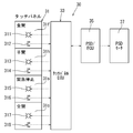
- the opening / closing control device 30 includes a touch panel 31, a touch panel ECU 33, a PSD / ECU 35, and a PSD motor 37 (motor 37).
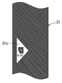
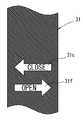
- the touch panel 31 is a panel that the user touches with a finger and is provided on the surface of the front frame 27f that forms the window frame outside the slide door 20, as shown in FIG. As shown in FIGS. 2 and 3, the touch panel 31 is provided with a fully-open operation unit 31 f, a half-open operation unit 31 h, a stop operation unit 31 s, and a fully-close operation unit 31 c.
- the fully open operation part 31f of the touch panel 31 is an operation part that is touch-operated when the slide door 20 is fully opened, and includes a fully open LED 311 and a fully open switch 312 including a capacitance sensor, as shown in FIG. .
- the half-open operation unit 31h of the touch panel 31 is an operation unit that performs a touch operation when the slide door 20 is half-opened, and includes a half-open LED 313 and a half-open switch 314 that includes a capacitance sensor.
- the stop operation unit 31 s of the touch panel 31 is an operation unit for urgently stopping the sliding door 20 that is being slid, and includes a stop LED 315 and a stop switch 316 including a capacitance sensor.
- the fully-closed operation unit 31c of the touch panel 31 is an operation unit that is touch-operated when the slide door 20 is fully closed, and includes a fully-closed LED 317 and a fully-closed switch 318 including a capacitance sensor.
- the touch panel 31 includes a light guide plate 321 that guides light from the stop LED 315 to the position of the stop operation unit 31 s, and an insulating film 322 is laminated on the light guide plate 321. Further, a capacitance sensor 323 (switch) is overlaid on the insulating film 322, and a screen 324 on which the pattern of the stop operation portion 31s is printed is laminated on the capacitance sensor 323. A translucent film 325 is laminated on the screen 324.
- the stop LED 315 and the like may be simply called a light source.
- the structure of the fully open operation part 31f, the half-open operation part 31h, and the fully closed operation part 31c is also the same as the structure of the operation part 31s for a stop, description is abbreviate
- the touch panel ECU 33 is a controller for transmitting signals input from the operation units 31f, 31h, 31s, and 31c of the touch panel 31 to the PSD / ECU 35 as shown in FIG. Further, the touch panel ECU 33 receives the signal from the PSD / ECU 35 and lights the LEDs 311, 313, 315, and 317 of the operation units 31 f, 31 h, 31 s, and 31 c of the touch panel 31 that can be operated according to the open / close state of the slide door 20. It is configured to be allowed to.
- the touch panel ECU 33 is configured to be able to invalidate the operation of the switches 312, 314, 316, and 318 in the operation units 31 f, 31 h, 31 s and 31 c in which the LEDs 311, 313, 315 and 317 are not lit.
- step S ⁇ b> 105 of FIG. 7 when the sliding operation unit 31 s of the touch panel 31 is not touched (NO in step S ⁇ b> 105 of FIG. 7) and the sliding door 20 reaches the fully open position, the motor 37 of the sliding door 20 is turned on.
- the slide door 20 is stopped and held at the fully open position (step S106 in FIG. 7). Accordingly, the stop LED 315 of the stop operation unit 31s of the touch panel 31 is turned off, and the fully closed LED 317 of the fully closed operation unit 31c is turned on as shown in the upper part of FIGS. 5D and 6. Thereby, the pattern of the fully-closed operation part 31c of the touch panel 31 can be seen, and the fully-closed operation part 31c becomes operable (step S107 in FIG. 7).
- the fully-closed switch 318 of the fully-closed operation unit 31c is turned on (YES in step S108 of FIG. 8). ), The motor 37 of the slide door 20 is driven, and the slide door 20 slides in the closing direction (step S109 in FIG. 8). Thereby, the fully-closed LED 317 of the fully-closed operation unit 31c of the touch panel 31 is turned off, and the stop LED 315 of the stop operation unit 31s is turned on. As a result, the stop operation unit 31s can be operated as described above (step S109 in FIG. 8).
- step S110 in FIG. 8 When the operation unit 31s for stopping the touch panel 31 is not touch-operated (NO in step S110 in FIG. 8), when the slide door 20 reaches the fully closed position, the motor 37 of the slide door 20 is stopped and the slide door 20 is moved. It is held in the fully closed position (step S111 in FIG. 8). As a result, the stop LED 315 of the stop operation unit 31s of the touch panel 31 is turned off, and the fully open LED 311 of the fully open operation unit 31f and the half open LED 313 of the half open operation unit 31h are lit as shown in the upper part of FIGS. As a result, the fully open operation part 31f and the half-open operation part 31h of the touch panel 31 can be operated (step S111 in FIG. 8).
- step S112 in FIG. 8 when the sliding door 20 is fully closed and locked while the sliding door 20 is in the fully closed position (YES in step S112 in FIG. 8), the fully open LED 311 and the half open operation part 31h of the fully open operation part 31f of the touch panel 31 are used.
- the half-open LED 313 is turned off, and the fully-open operation part 31f and the half-open operation part 31h become inoperable (step S113 in FIG. 8).
- step S123 of FIG. 7 when the sliding operation unit 31s of the touch panel 31 is not touch-operated (NO in step S123 of FIG. 7) and the sliding door 20 reaches the half-open position, the motor 37 of the sliding door 20 is turned on. The slide door 20 is stopped and held in the half-open position (step S124 in FIG. 7). As a result, the stop LED 315 of the stop operation unit 31s of the touch panel 31 is turned off, and the fully closed LED 317 of the fully closed operation unit 31c and the fully open LED 311 of the fully open operation unit 31f are turned on as shown in the middle stages of FIGS. . Therefore, the fully closing operation part 31c and the fully opening operation part 31f of the touch panel 31 can be operated (step S125 in FIG. 7).
- step S105 when the stop operation unit 31s of the touch panel 31 is touched while the slide door 20 is sliding (YES in step S105 in FIG. 7, YES in step S123, YES in step 110 in FIG. 8), the slide The door 20 stops at that position (step S126 in FIG. 7). Then, the stop LED 315 of the stop operation unit 31s of the touch panel 31 is turned off, and the fully closed LED 317 of the fully closed operation unit 31c and the fully open LED 311 of the fully open operation unit 31f are turned on as shown in the lower part of FIG. 5A and FIG. Therefore, the fully closing operation part 31c and the fully opening operation part 31f of the touch panel 31 can be operated (step S125 in FIG. 7). The operation of the slide door 20 after touching the fully-closed operation unit 31c or the fully-opened operation unit 31f of the touch panel 31 is the same as the above-described operation.
- the LEDs 311, 313, 315, and 317 (light sources) corresponding to the operation units 31 f, 31 h, 31 s, and 31 c that can be operated according to the opening / closing state of the slide door 20. Lights up and the patterns (displays) of the operable operation units 31f, 31h, 31s, and 31c can be seen.
- the LEDs 311 and 313 corresponding to the operation units in the opening direction of the slide door 20 are turned on, and the full-open operation unit 31f and half-open operation unit The pattern (display) of 31h becomes visible.
- the LED 317 corresponding to the operation part (full close operation part 31c) in the closing direction of the slide door is turned on, and the display of the full close operation part 31c becomes visible. For this reason, even a user who is not used to the touch panel 31 can easily use the touch panel 31.
- the touch panel 31 is provided on the front frame 27 f that forms the window frame of the slide door 20. That is, since the touch panel 31 can be disposed near the grip handle 25h of the slide door 20, the touch panel 31 can be easily touched when the slide door 20 is opened and closed.
- the touch panel 31 is provided on the front frame 27f constituting the window frame of the slide door 20 in the present embodiment.
- the touch panel 31 along the grip handle 25h at a height position substantially equal to the grip handle 25h of the slide door 20.
- the touch panel 31 and the grip handle 25h can be integrated. It is also possible to provide the touch panel 31 on the side surface of the body near the slide door 20.
- the operations of the switches 312, 314, 316, and 318 of all the operation units 31 f, 31 h, 31 s, and 31 c of the touch panel 31 are invalidated. I made it.
- the ECU such as the PSD / ECU 35 detects that the user has approached with the authentication key, even if the slide door 20 is in the fully closed lock state, The fully open operation part 31f may be operable.
Landscapes
- Engineering & Computer Science (AREA)
- Theoretical Computer Science (AREA)
- General Engineering & Computer Science (AREA)
- Mechanical Engineering (AREA)
- Human Computer Interaction (AREA)
- Physics & Mathematics (AREA)
- General Physics & Mathematics (AREA)
- Power-Operated Mechanisms For Wings (AREA)
Abstract
Priority Applications (2)
| Application Number | Priority Date | Filing Date | Title |
|---|---|---|---|
| CN201480003150.6A CN104797771B (zh) | 2013-06-14 | 2014-05-26 | 滑动门的开闭控制装置 |
| US14/646,259 US20150315839A1 (en) | 2013-06-14 | 2014-05-26 | Opening-closing control device of slide door |
Applications Claiming Priority (2)
| Application Number | Priority Date | Filing Date | Title |
|---|---|---|---|
| JP2013-125631 | 2013-06-14 | ||
| JP2013125631A JP6168552B2 (ja) | 2013-06-14 | 2013-06-14 | スライドドアの開閉制御装置 |
Publications (1)
| Publication Number | Publication Date |
|---|---|
| WO2014199807A1 true WO2014199807A1 (fr) | 2014-12-18 |
Family
ID=52022106
Family Applications (1)
| Application Number | Title | Priority Date | Filing Date |
|---|---|---|---|
| PCT/JP2014/063839 Ceased WO2014199807A1 (fr) | 2013-06-14 | 2014-05-26 | Dispositif de commande d'ouverture et de fermeture de porte coulissante |
Country Status (4)
| Country | Link |
|---|---|
| US (1) | US20150315839A1 (fr) |
| JP (1) | JP6168552B2 (fr) |
| CN (1) | CN104797771B (fr) |
| WO (1) | WO2014199807A1 (fr) |
Families Citing this family (15)
| Publication number | Priority date | Publication date | Assignee | Title |
|---|---|---|---|---|
| DE102016218693A1 (de) | 2016-09-28 | 2018-03-29 | Volkswagen Aktiengesellschaft | Türgriff, Türinnenverkleidung und Fortbewegungsmittel |
| JP6771352B2 (ja) * | 2016-10-06 | 2020-10-21 | 三井金属アクト株式会社 | ドア開閉装置のスイッチ |
| JP6905887B2 (ja) * | 2017-07-24 | 2021-07-21 | 株式会社アイシン | 車両用操作検出装置及びスライドドア装置 |
| US10378254B1 (en) | 2018-05-16 | 2019-08-13 | Ford Global Technologies, Llc | Vehicle door handle having proximity sensors for door control and keypad |
| US10633910B2 (en) | 2018-05-16 | 2020-04-28 | Ford Global Technologies, Llc | Vehicle door having variable speed power assist |
| US10435924B1 (en) | 2018-06-26 | 2019-10-08 | Ford Global Technologies, Llc | Vehicle door handle having ice handling |
| US11078691B2 (en) | 2018-06-26 | 2021-08-03 | Ford Global Technologies, Llc | Deployable vehicle door handle |
| CN110725633B (zh) * | 2018-06-28 | 2021-01-19 | 比亚迪股份有限公司 | 解锁车门的方法和装置、存储介质和车辆 |
| US10599260B1 (en) | 2018-10-22 | 2020-03-24 | Ford Global Technologies, Llc | System and methods for exterior vehicle display |
| US10719287B2 (en) | 2018-11-13 | 2020-07-21 | Ford Global Technologies, Llc | Vehicle video displays |
| US10633895B1 (en) | 2019-02-26 | 2020-04-28 | Ford Global Technologies, Llc | Deployable vehicle door handle having lighting |
| JP7221738B2 (ja) * | 2019-03-05 | 2023-02-14 | 株式会社アイシン | 車両用操作検出装置 |
| US10850711B2 (en) * | 2019-05-03 | 2020-12-01 | Ford Global Technologies, Llc | System and methods for exterior vehicle display and panel exciters |
| US11104277B2 (en) * | 2020-01-08 | 2021-08-31 | Honda Motor Co., Ltd. | Vehicle-mounted display device |
| JP7510113B2 (ja) * | 2020-09-02 | 2024-07-03 | 三菱自動車工業株式会社 | ドア開閉装置 |
Citations (4)
| Publication number | Priority date | Publication date | Assignee | Title |
|---|---|---|---|---|
| JPH0158302B2 (fr) * | 1982-03-30 | 1989-12-11 | Nitsusan Jidosha Kk | |
| JPH02112884U (fr) * | 1989-02-17 | 1990-09-10 | ||
| JPH0642072Y2 (ja) * | 1988-02-20 | 1994-11-02 | 愛三工業株式会社 | 車両のスライドドア全開装置 |
| JP2013072177A (ja) * | 2011-09-26 | 2013-04-22 | Nabtesco Corp | 自動ドア |
Family Cites Families (5)
| Publication number | Priority date | Publication date | Assignee | Title |
|---|---|---|---|---|
| JP5309515B2 (ja) * | 2007-09-25 | 2013-10-09 | アイシン精機株式会社 | 車両用ドア開閉制御装置 |
| JP5015854B2 (ja) * | 2008-04-24 | 2012-08-29 | アスモ株式会社 | 開閉装置 |
| DE102011018234A1 (de) * | 2010-04-21 | 2012-02-02 | Marquardt Gmbh | Bedienvorrichtung |
| TW201344442A (zh) * | 2012-04-25 | 2013-11-01 | Hon Hai Prec Ind Co Ltd | 車輛控制系統 |
| CN202716828U (zh) * | 2012-08-29 | 2013-02-06 | 上海博泰悦臻电子设备制造有限公司 | 车载控制输入装置、车载系统及汽车 |
-
2013
- 2013-06-14 JP JP2013125631A patent/JP6168552B2/ja active Active
-
2014
- 2014-05-26 US US14/646,259 patent/US20150315839A1/en not_active Abandoned
- 2014-05-26 WO PCT/JP2014/063839 patent/WO2014199807A1/fr not_active Ceased
- 2014-05-26 CN CN201480003150.6A patent/CN104797771B/zh active Active
Patent Citations (4)
| Publication number | Priority date | Publication date | Assignee | Title |
|---|---|---|---|---|
| JPH0158302B2 (fr) * | 1982-03-30 | 1989-12-11 | Nitsusan Jidosha Kk | |
| JPH0642072Y2 (ja) * | 1988-02-20 | 1994-11-02 | 愛三工業株式会社 | 車両のスライドドア全開装置 |
| JPH02112884U (fr) * | 1989-02-17 | 1990-09-10 | ||
| JP2013072177A (ja) * | 2011-09-26 | 2013-04-22 | Nabtesco Corp | 自動ドア |
Also Published As
| Publication number | Publication date |
|---|---|
| US20150315839A1 (en) | 2015-11-05 |
| CN104797771A (zh) | 2015-07-22 |
| CN104797771B (zh) | 2016-08-17 |
| JP2015001088A (ja) | 2015-01-05 |
| JP6168552B2 (ja) | 2017-07-26 |
Similar Documents
| Publication | Publication Date | Title |
|---|---|---|
| JP6168552B2 (ja) | スライドドアの開閉制御装置 | |
| US11542731B2 (en) | Smart handle assembly with force-based sensor and backup energy source | |
| JP5382050B2 (ja) | 車両用開閉体作動装置 | |
| CN104114799A (zh) | 车辆用开闭体控制装置 | |
| KR20200016334A (ko) | 자동차용 조작 장치 | |
| KR102123342B1 (ko) | 이미지 기록 유닛 및 차량의 장치들을 조작하기 위한 조작 시스템을 구비한 차량 및 조작 시스템을 작동하기 위한 방법 | |
| CN104114800A (zh) | 车辆用开闭体控制装置 | |
| EP1978535B1 (fr) | Panneau de commande situé sur un accoudoir de portière de véhicule | |
| CN107521433A (zh) | 具有能运动的窗玻璃的机动车装置、机动车和运行方法 | |
| JP6837313B2 (ja) | ウインドウ制御装置 | |
| CN104220284B (zh) | 天窗的开关装置 | |
| JP7095557B2 (ja) | 車両用パワーウインドウ制御装置 | |
| CN110785310A (zh) | 机动车操作设备 | |
| JP2019196664A (ja) | 車両用ドア制御装置 | |
| JP7543178B2 (ja) | 操作装置 | |
| CN110770068A (zh) | 用于开关在机动车中的驱动装置的开关装置 | |
| KR102100983B1 (ko) | 차량용 파워 윈도우 스위치 장치 | |
| JP2019100063A (ja) | 開閉体制御装置 | |
| US20190301232A1 (en) | Manipulation detecting device for vehicle | |
| JP6828534B2 (ja) | 車両用操作検出装置 | |
| US20060186847A1 (en) | Control arrangement for a control element for opening and closing a vehicle panel | |
| JP2013170391A (ja) | 車両用開閉体制御装置 | |
| JP6372199B2 (ja) | 開閉体の自動開閉システム | |
| JP7376841B2 (ja) | ドアロック装置及びドア | |
| JP2018155069A (ja) | パワーウィンドウ制御装置 |
Legal Events
| Date | Code | Title | Description |
|---|---|---|---|
| 121 | Ep: the epo has been informed by wipo that ep was designated in this application |
Ref document number: 14810395 Country of ref document: EP Kind code of ref document: A1 |
|
| WWE | Wipo information: entry into national phase |
Ref document number: 14646259 Country of ref document: US Ref document number: IDP00201503005 Country of ref document: ID |
|
| NENP | Non-entry into the national phase |
Ref country code: DE |
|
| 122 | Ep: pct application non-entry in european phase |
Ref document number: 14810395 Country of ref document: EP Kind code of ref document: A1 |