WO2014199973A1 - 芯取り加工装置及び芯取り加工方法 - Google Patents
芯取り加工装置及び芯取り加工方法 Download PDFInfo
- Publication number
- WO2014199973A1 WO2014199973A1 PCT/JP2014/065315 JP2014065315W WO2014199973A1 WO 2014199973 A1 WO2014199973 A1 WO 2014199973A1 JP 2014065315 W JP2014065315 W JP 2014065315W WO 2014199973 A1 WO2014199973 A1 WO 2014199973A1
- Authority
- WO
- WIPO (PCT)
- Prior art keywords
- bell holder
- bell
- holder
- centering
- support device
- Prior art date
- Legal status (The legal status is an assumption and is not a legal conclusion. Google has not performed a legal analysis and makes no representation as to the accuracy of the status listed.)
- Ceased
Links
Images







Classifications
-
- B—PERFORMING OPERATIONS; TRANSPORTING
- B24—GRINDING; POLISHING
- B24B—MACHINES, DEVICES, OR PROCESSES FOR GRINDING OR POLISHING; DRESSING OR CONDITIONING OF ABRADING SURFACES; FEEDING OF GRINDING, POLISHING, OR LAPPING AGENTS
- B24B9/00—Machines or devices designed for grinding edges or bevels on work or for removing burrs; Accessories therefor
- B24B9/02—Machines or devices designed for grinding edges or bevels on work or for removing burrs; Accessories therefor characterised by a special design with respect to properties of materials specific to articles to be ground
- B24B9/06—Machines or devices designed for grinding edges or bevels on work or for removing burrs; Accessories therefor characterised by a special design with respect to properties of materials specific to articles to be ground of non-metallic inorganic material, e.g. stone, ceramics, porcelain
- B24B9/08—Machines or devices designed for grinding edges or bevels on work or for removing burrs; Accessories therefor characterised by a special design with respect to properties of materials specific to articles to be ground of non-metallic inorganic material, e.g. stone, ceramics, porcelain of glass
- B24B9/14—Machines or devices designed for grinding edges or bevels on work or for removing burrs; Accessories therefor characterised by a special design with respect to properties of materials specific to articles to be ground of non-metallic inorganic material, e.g. stone, ceramics, porcelain of glass of optical work, e.g. lenses, prisms
- B24B9/146—Accessories, e.g. lens mounting devices
Definitions
- the present invention generally relates to a centering apparatus and a centering method, and more particularly, to a centering apparatus and a centering method for performing centering while sandwiching an optical element.
- the lens is centered while sandwiching the lens with the bell holder prior to the centering processing. Therefore, when the lens is sandwiched or during subsequent centering, the lens is positioned at the tip of the bell holder. There is a problem that the lens surface is damaged and the lens surface is scratched.
- the present invention has been made to solve such a problem, and a centering apparatus capable of suppressing the problem of scratching the surface of the lens when the lens is sandwiched or subsequently centered. It is another object of the present invention to provide a centering method.
- an optical element centering apparatus that performs centering by sandwiching the optical element between the tips of the first and second bell holders.
- the first and second support devices are provided so as to be close to and separate from each other so that the front end of one bell holder and the front end of the second bell holder are coaxially opposed to each other.
- the first support device has an elastic member that elastically supports the first bell holder on the axis of the first bell holder, and the first bell holder extends in the rear end direction.
- a centering apparatus configured to be elastically retractable.
- the optical element is sandwiched and centered by the first and second bell holders while at least the bell holder supported by the first support apparatus is elastically retracted.
- the impact when the bell holder supported by at least the first support device comes into contact with the optical element is alleviated, and the damage of the optical element when the optical element is laterally displaced during centering is suppressed.
- a centering method for an optical element in which the optical element is sandwiched between the tips of the first and second bell holders, and at least one surface is a curved surface.
- the optical element is clamped between the tips of the first and second bell holders while the apparatus is approached and at least one of the first and second bell holders is elastically retracted;
- a centering method including a step of centering an optical element while rotating the optical element together with the first and second bell holders.
- the processing method having such a configuration, in the centering step, at least one of the first and second bell holders is elastically retracted with respect to the support device, and the first and second bell holders are used. Since the optical element is sandwiched and centered, the impact when the first and second bell holders come into contact with the optical element is alleviated, and further, the optical element is damaged when the optical element is laterally shifted during centering. It is suppressed.
- a centering method for an optical element in which the optical element is sandwiched between the tips of the first and second bell holders, and at least one surface is a curved surface.
- the optical element is clamped between the tips of the first and second bell holders while the apparatus is approached and at least one of the first and second bell holders is elastically retracted;
- a first support device that supports one bell holder and a second support device that supports a second bell holder are further brought closer together, and a tip end of a third bell holder fixedly supported by the first support device; 2 is fixedly supported by the support device And centering the optical element while rotating the optical element together with the first and second bell holders, and centering the optical element.
- the optical element is clamped and centered by the first and second bell holders while at least the bell holder supported by the first support device is elastically retracted.
- the impact when the bell holder supported by at least the first support device comes into contact with the optical element is alleviated, and the damage of the optical element when the optical element is laterally displaced during centering is suppressed.
- a centering device and a centering method that can suppress the problem of scratching the surface of the lens when the lens is sandwiched or centered.
- FIG. 1 is a schematic longitudinal sectional view showing the main part of the centering apparatus 1 according to the first embodiment of the present invention.
- the centering apparatus 1 is an apparatus used in the process of manufacturing an optical element such as a lens (for example, a glass lens), and sandwiches the optical element between the tips of upper and lower bell holders. Thus, it is a device that performs so-called centering processing. Since the configuration other than the main part shown in FIG. 1 is the same as that of a known centering apparatus, description thereof is omitted.
- the configuration of the centering apparatus of the present invention is such that a chamfering process, an D-cut process, an I-cut process, or an optical element such as a lens manufactured by press molding is used. It is also possible to apply to an apparatus for performing a process for removing the.
- the centering device 1 of the first embodiment includes a lower support device 2 and an upper support device 4 that support the bell holder.
- the lower support device 2 and the upper support device 4 have the same structure and are arranged to face each other vertically.
- the lower support device 2 includes a lower bell holder 6 and a lower inner bell holder 8.
- the lower bell holder 6 and the lower inner bell holder 8 have a bottomed cylindrical shape.
- a through hole K ′ is formed at the bottom of the lower bell holder 6, and a through hole K is formed at the bottom of the lower inner bell holder 8.
- a through hole K ′′ is formed in the base of the lower support device 2, and the inner space of the lower bell holder 6 is disposed outside the lower support device 2 through the through holes K, K ′, K ′′. It is configured to communicate with a suction device (not shown).
- the outer diameter of the lower inner bell holder 8 is set to be substantially equal to the inner diameter of the lower bell holder 6, and the lower inner bell holder 8 is concentrically disposed inside the lower bell holder 6.
- “nesting type” means a state in which a large-diameter cylindrical member and a small-diameter cylindrical member are concentrically combined.
- the lower bell holder 6 is supported by the lower support device 2 so as not to move in the axial direction with respect to the lower support device 2.
- the lower inner bell holder 8 is supported by the lower support device 2 so as to be movable in the axial direction with respect to the lower support device 2.
- the lower support device 2 includes a coil spring 10 as an elastic member on the rear end side of the lower inner bell holder 8.
- the coil spring 10 elastically supports the rear end 8b of the lower inner bell holder 8 in the axial direction.
- the lower inner bell holder 8 is arranged such that the tip 8a protrudes forward from the tip 6a of the lower bell holder 6 when no force from the tip to the rear end is applied. (FIG. 1).
- the lower inner bell holder 8 When the lower inner bell holder 8 receives a force from the front end portion 6a toward the rear end 6b, the lower inner bell holder 8 compresses the coil spring 10, and in the direction indicated by the arrow A in FIG. Retreats elastically while resisting.
- the internal space of the lower inner bell holder 8 is decompressed through the through holes K, K ′, K ′′ by a suction device (not shown), and the optical element to be processed is moved to the lower inner side.
- the bell holder 8 is configured to be sucked and fixed to the tip 8a.
- the upper support device 4 has basically the same structure as the lower support device 2, but is attached to a lifting mechanism (not shown), and in the direction indicated by the arrow B in FIG. It can be moved toward and away from the side support device 2.
- the upper support device 4 includes an upper bell holder 12 and an upper inner bell holder 14.
- the upper bell holder 12 and the upper inner bell holder 14 have a cylindrical shape.
- the outer diameter of the upper inner bell holder 14 is set to be substantially equal to the inner diameter of the upper bell holder 12, and the upper inner bell holder 14 is concentrically disposed inside the upper bell holder 12.
- the upper bell holder 12 is supported by the upper support device 4 so as not to move in the axial direction with respect to the upper support device 4.
- the upper inner bell holder 14 is supported by the upper support device 4 so as to be movable in the axial direction with respect to the upper support device 4.
- the upper support device 4 includes a coil spring 16 on the rear end side of the upper inner bell holder 14.
- the coil spring 16 elastically supports the rear end portion 14b of the upper inner bell holder 14 in the axial direction.
- the upper inner bell holder 14 is arranged such that the front end portion 14a is positioned so as to protrude forward from the front end portion 12a of the upper bell holder 12 in a state where a force from the front end portion 14a toward the rear end portion 14b is not acting. (Fig. 1).
- the upper inner bell holder 14 When the upper inner bell holder 14 receives a force from the front end portion 12a toward the rear end portion 12b, the upper inner bell holder 14 compresses the coil spring 16, and in the direction indicated by the arrow C in FIG. 1, the spring force toward the front end portion 12a from the rear end portion 12b. Retracts elastically while resisting.
- the lower inner bell holder 8 and the upper inner bell holder 14 are made of carbon, ceramics, resin (for example, PEEK (polyester)) that is softer than glass that is the material of the optical element to be processed. It is formed of a soft material such as ether ether ketone)).
- the lower bell holder 6 and the upper bell holder 12 are formed of a hard material such as a metal material (for example, NAK) harder than glass, which is a material of the optical element to be processed.
- the diameters of the lower bell holder 6, the lower inner bell holder 8, the upper bell holder 12, and the upper inner bell holder 14 are appropriately set according to the dimensions of the optical element such as a lens to be centered.
- the lower bell holder 6 and the upper bell holder 12 have the same diameter
- the lower inner bell holder 8 and the upper inner bell holder 14 have the same diameter.
- the tips of the lower bell holder 6, the lower inner bell holder 8, the upper bell holder 12, and the upper inner bell holder 14 are inclined surfaces whose inner side in the radial direction is lowered.
- the hardness of the lower bell holder 6 (Knoop hardness Hk) is higher than the hardness of the optical element
- the hardness of the lower inner bell holder 8 (Knoop hardness Hk) is the hardness of the optical element (Knoop hardness). Hk) is set lower.
- the hardness of the upper bell holder 12 (Knoop hardness Hk) is set higher than the hardness of the optical element (Knoop hardness Hk), and the hardness of the upper inner bell holder 14 (Knoop hardness Hk) is set lower than the hardness of the optical element. Yes.
- the lower support device 2 and the upper support device 4 are arranged so that the center axes of the bell holders 6, 8, 12, 14 are aligned in the same manner as the known centering device.
- the rear end side is attached to the rotary shaft of the rotary drive device, and this aligned axis becomes the holder axis X, which can be rotated around the holder axis X of each of the bell holders 6, 8, 12, and 14.
- the tips of the lower inner bell holder 8 and the upper inner bell holder 14 that are elastically retractable protrude forward from the tips of the lower bell holder 6 and the upper bell holder 12 that do not move in the axial direction. Therefore, when sandwiching an optical element such as a lens, first, the tips of the lower inner bell holder 8 and the upper inner bell holder 14 that are formed of a soft material and project forward are placed on the surface of the optical element. Contact.
- the optical element is sandwiched and centered by the lower inner bell holder 8 and the upper inner bell holder 14 while the lower inner bell holder 8 and the upper inner bell holder 14 are elastically retracted. For this reason, the collision pressure when the lower inner bell holder 8 and the upper inner bell holder 14 come into contact with the optical element is relieved, and the occurrence of collision scratches (such as indentations or contact marks by the bell holder) due to the bell holders can be prevented. Furthermore, by reducing the clamping pressure received when the optical element is laterally displaced during centering, it is possible to prevent the occurrence of scratches caused by the bell holder (indentation or contact mark caused by the bell holder).
- the indentation and the contact mark cannot be detected, for example, in the visual visual inspection of the optical element. Further, indentations and contact marks are not observed even when enlarged to a high magnification (for example, 1000 times or more) with SEM (Scanning Electron Microscope).
- the lower inner bell holder 8 and the upper inner bell holder 14 are formed of a soft material such as carbon, ceramics, resin, etc., so that the optical element is laterally shifted during centering. The damage of the optical element at the time is more effectively suppressed.
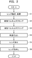
- FIG. 2 is a flowchart showing the contents of a lens centering method performed using the centering apparatus 1 of this embodiment.
- the lower support device 2 and the upper support device 4 are attached to the rotary shaft of the rotary drive device so that the lower support device 2 and the upper support device 4 can rotate about the holder axis X. Further, the upper support device 4 is movable in the arrow B direction with respect to the lower support device 2.
- a lens (biconvex lens) L which is an optical element to be centered, is placed on the tip 8a of the lower inner bell holder 8 made of a soft material (FIG. 3).
- the center axis O of the lens L does not coincide with the holder axis X when placed on the tip 8 a of the lower inner bell holder 8.
- the internal space of the lower inner bell holder 8 is decompressed through the through holes K, K ′, K ′′ by a suction device (not shown). Is temporarily fixed to the front end portion 8a of the lower inner bell holder 8 made of a soft material.
- the through holes K, K ′, K ′′ are formed on the lower support device 2 side, but such through holes are not essential in the present invention.
- an elevating mechanism (not shown) to which the upper support device 4 is attached is operated, and the upper support device 4 is moved so that the tip portion 14 a of the upper inner bell holder 14 is the tip portion of the lower inner bell holder 8.
- the lens L is lowered to a position where it abuts on the upper surface of the lens L temporarily fixed to 8a, and the lens L is clamped by being sandwiched between the tip portion 8a of the lower inner bell holder 8 and the tip portion 14a of the upper inner bell holder 14. Centered (clamped with soft bell holder).
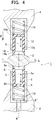
- the lens L When the lens L is sandwiched between the tip portion 8a of the lower inner bell holder 8 and the tip portion 14a of the upper inner bell holder 14, the lens L is centered by a force acting upon the clamping, which is schematically shown in FIG. As shown in FIG. 4, the central axis (lens optical axis) O is substantially aligned with the holder axis X (FIG. 4).
- the upper support device 4 is further lowered as shown by an arrow B by an elevating mechanism (not shown) to which the upper support device 4 is attached, and the lower support device 2 and the upper support device 4 are moved. Further approach.
- the lens L includes, in addition to the distal end portion 12a of the upper bell holder 12 and the distal end portion 8a of the lower inner bell holder 8, the distal end portion 14a of the upper inner bell holder 14 formed of a hard material and the distal end portion of the lower bell holder 6. 6a is clamped by clamping, and is more accurately centered (clamping with a hard bell holder).
- lens centering is performed.
- the tip portion 12a of the upper bell holder 12, the tip portion 14a of the upper inner bell holder 14, the tip portion 8a of the lower inner bell holder 8, and The grinding stone G is brought into contact with the outer peripheral edge of the lens L sandwiched between the front end portions 6 a of the lower bell holder 6, and the outer peripheral edge of the lens L is ground by the grinding stone G.
- the center axis of the lens outer periphery of the lens L coincides with the lens optical axis (FIG. 7).
- the rotation of the lower support device 2 and the upper support device 4 is temporarily stopped, and the support pressure of the bell holder is switched to a pressure higher than the support pressure at the time of high-speed centering.
- the lower support device 2 and the upper support device 4 are rotated.
- the rotational speed at this time is set to a speed lower than the rotational speeds of the lower support device 2 and the upper support device 4 at the time of high-speed centering.
- the lower support device 2 and the upper support device 4 are stopped, the upper support device 4 is moved upward, the lens L is removed from the centering device 1 (S6), and the centering step. Ends.
- the tips of the lower inner bell holder 8 and the upper inner bell holder 14 that can be elastically retracted do not move in the axial direction. Since the optical element to be centered such as a lens is clamped, the tips of the lower inner bell holder 8 and the upper inner bell holder 14 that are elastically retractable are first positioned at the front side of the optical element. Contact the surface.
- the lower bell holder 6 and the upper bell holder 12 are further brought closer to each other. Since centering is performed once, centering can be performed with higher accuracy than the conventional method. Therefore, the movement amount (deviation amount) at the time of high-speed centering becomes a very small amount, and the generation of scratches at this stage is suppressed.
- the lower inner bell holder 8 and the upper inner bell holder 14 are made of a soft material, so that the optical element is more effectively damaged when the optical element is laterally displaced during centering. It is suppressed.
- the lower support device 2 supports the optical element by sucking the optical element, a larger force is required to move the optical element by the amount of the suction force at the time of centering. It becomes easy to be damaged.
- the bell holder supported by the lower support device 2 abuts against the optical element while elastically retreating, so that the impact at the time of abutment is alleviated and the optical element is laterally shifted during centering. The damage of the optical element at the time is suppressed.
- the lower inner bell holder 8 and the upper inner bell holder 14 are made of a soft material
- the lower bell holder 6 and the upper bell holder 12 are made of a hard material
- the lower bell holder 6 and the upper bell holder 12 may also be formed of a soft material.
- the four bell holders that is, the lower bell holder 6, the lower inner bell holder 8, the upper bell holder 12, and the upper inner bell holder 14 may be formed of the same material.
- the soft material bell holder that can be retracted in the axial direction is provided with the lower inner bell holder 8 and the upper support device.
- the inner bell holder 14 is arranged on the inner side.
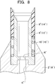
- At least one of the lower and upper support devices is elastically moved in the axial direction by a coil spring 10 '(16') as in the support device 2 '(4') shown in FIG.
- a configuration is possible in which the retractable soft material bell holder 8 '(14') is arranged on the outer side of the upper or lower bell holder 6 '(12') which does not move in the axial direction.
- the bell holder 8 ′ (14 ′) made of a soft material that can be retracted in the axial direction has an upper or lower bell holder 6 in which the tip does not move in the axial direction in a state where no force is applied from the tip to the rear end. It arrange
- FIG. 9 is a view showing a main part of the centering apparatus 20 according to the second embodiment of the present invention.
- the centering device 20 of the second embodiment does not include a bell holder that does not move in the axial direction with respect to the lower support device 22 and the upper support device 24, and the lower support device 22 and the upper support device 24 are respectively soft.
- a lower bell holder 26 and an upper bell holder 28 that are made of a material and elastically retractable in the axial direction are provided.
- the lower bell holder 26 and the upper bell holder 28 can be elastically retracted in the axial direction by the coil springs 30 and 32 arranged at the rear end, similarly to the centering device 1 of the first embodiment.
- the lower support device 22 is configured so that the internal space of the lower bell holder 26 can be decompressed and the optical element to be processed can be sucked and fixed to the distal end portion 26 a of the lower bell holder 26.
- the upper support device 24 is attached to an elevating mechanism (not shown) and can approach and separate toward the lower support device 22.
- the bell holder that does not retreat in the axial direction is preferably formed of a hard material.
- FIG. 10 is a view showing a main part of the centering device 33 according to the third embodiment of the present invention.
- the centering device 33 of the third embodiment has the same configuration on the lower support device side as the configuration on the lower support device 2 side of the centering device 1 of the first embodiment.
- the upper support device 34 includes a bell holder 36 that is formed of a hard material and does not move in the axial direction with respect to the upper support device 34.
- Such a configuration is suitable for the centering process for the lens L2 having a shape in which only one side surface (the lower surface in FIG. 10) is easily damaged as shown in FIG.
- the lower support device 2 is configured so that the inner space of the lower inner bell holder 8 can be decompressed and the optical element to be processed can be sucked and fixed to the distal end portion 8 a of the lower inner bell holder 8.
- the upper support device 34 is attached to an elevating mechanism (not shown) and can be moved toward and away from the lower support device 2.
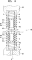
- FIG. 11 is a view showing a main part of the centering device 40 according to the fourth embodiment of the present invention.
- the centering device 40 of the fourth embodiment includes a lower support device 42 and an upper support device 44 that support the bell holder, as in the above embodiments.
- the lower support device 42 of the centering device 40 has a configuration similar to that of the lower support device 2 of the centering device 1 of the first embodiment.
- the difference between the lower support device 42 and the lower support device 2 of the centering apparatus 1 of the first embodiment is that, in the lower support device 42, the lower support device 42 is disposed radially outward of the lower bell holder 46.
- a lower outer bell holder 48 that is movable in the axial direction with respect to 42 is further provided.
- the lower support device 42 of the centering device 40 of this embodiment includes a lower bell holder 46 and a lower inner bell holder in which the coil spring 50 is disposed on the rear end side. 52 and a lower outer bell holder 48 which is disposed radially outward of the lower bell holder 46 and has a coil spring 54 disposed on the rear end side.
- the lower bell holder 46 does not move in the axial direction, and the lower outer bell holder 48 and the lower inner bell holder 52 are movable in the axial direction. It is configured.
- the tip 46a of the lower bell holder 46 is located on the most rear end side when no force is acting in the axial direction.
- the front end portion 52a of the lower inner bell holder 52 is located on the most front end side.
- the front end portion 48 a of the lower outer bell holder 48 is positioned at the axial position between the front end portion 46 a of the lower bell holder 46 and the front end portion 52 a of the lower inner bell holder 52.
- the lower inner bell holder 52 and the lower outer bell holder 48 are formed of a soft material, and the lower bell holder 46 is formed of a hard material.
- the lower support device 42 is configured so that the internal space of the lower inner bell holder 52 can be decompressed and the optical element to be processed can be sucked and fixed to the distal end portion 52 a of the lower inner bell holder 52. .
- the upper support device 44 is attached to an elevating mechanism (not shown), and can be moved toward and away from the lower support device 42.
- the upper support device 44 of the centering device 40 also has a configuration similar to that of the upper support device 4 of the centering device 1 of the first embodiment.
- the difference between the upper support device 44 and the upper support device 4 of the centering device 1 of the first embodiment is that the upper support device 44 is disposed radially outward of the upper bell holder 56 relative to the upper support device 44.
- the upper outer bell holder 58 is movable in the axial direction.
- the upper support device 44 of the centering device 40 of the present embodiment includes an upper bell holder 56, an upper inner bell holder 62 that is disposed on the inner side of the upper bell holder 56, and in which a coil spring 60 is disposed on the rear end side.
- An upper outer bell holder 58 disposed outside the bell holder 56 and having a coil spring 64 disposed on the rear end side thereof is provided.
- the upper bell holder 56 does not move in the axial direction, and the upper outer bell holder 58 and the upper inner bell holder 62 are configured to be movable in the axial direction. .
- the tip 56a of the upper bell holder 56 is located on the most rear end side when no force is acting in the axial direction.
- the distal end portion 62a of the upper inner bell holder 62 is located on the most distal end side.
- the front end 58 a of the upper outer bell holder 58 is positioned at the axial position between the front end 56 a of the upper bell holder 56 and the front end 62 a of the upper inner bell holder 62.
- the upper inner bell holder 62 and the upper outer bell holder 58 are formed of a soft material, and the upper bell holder 56 is formed of a hard material.
- the lower bell holder 46 and the upper bell holder 56 which are bell holders located in the middle of the bell holders arranged in a triple structure, are made of a hard material, but the outer bell holder or the inner bell holder is made of a hard material. It may also be configured.
- the bell holder on which the hard material is formed is fixed to the support device, and the tip thereof is disposed so as to recede from the other bell holder.
- the centering apparatus having such a configuration, when the upper support device 44 is moved closer to the lower support device 42 when the optical element (for example, the lens L3) is sandwiched, the lens L3 is first lowered. It is sandwiched between the side inner bell holder 52 and the upper inner bell holder 62. At this time, the centering of the lens L3 is performed.
- the optical element for example, the lens L3
- the lower inner bell holder 52 and the upper inner bell holder 62 are elastically retracted in the rear end direction.
- the lens L3 is sandwiched between the lower inner bell holder 52, the lower outer bell holder 48, the upper inner bell holder 62, and the upper outer bell holder 58. At this time, the centering of the lens L3 is performed again.
- the lens L3 When the upper support device 44 is further moved closer to the lower support device 42, the lower inner bell holder 52 and the lower outer bell holder 48, and the upper inner bell holder 62 and the upper outer bell holder 58 cause the lens L3 to move. It is elastically retracted toward the rear end while being clamped from above and below.
- the lens L3 is sandwiched between the tips of the lower bell holder 46 and the upper bell holder 56, the movement of the upper support device 44 to the lower support device 42 is stopped.
- the lens L3 is also centered when it is sandwiched between the tips of the lower bell holder 46 and the upper bell holder 56.
- the centering accuracy of the lens L3 can be increased because the centering of the lens L3 is performed three times.
- FIG. 12 is a schematic longitudinal sectional view showing the main part of the centering apparatus 70 according to the fifth embodiment of the present invention.
- the centering device 70 of the present embodiment has a basic configuration similar to the centering device 1 of the first embodiment.
- the configuration of the centering device 70 of the present embodiment will be described focusing on the differences from the centering device 1 of the first embodiment.
- the centering device 70 of the fifth embodiment includes a lower support device 72 and an upper support device 74 that support a cylindrical bell holder.
- the lower support device 72 and the upper support device 74 have a tapered shape near the tip.
- the configuration on the lower support device 72 side and the configuration on the upper support device 74 side are the same, but the configuration on the lower support device 72 side and the configuration on the upper support device 74 side may be different. .
- the lower support device 72 supports a cylindrical lower outer bell holder 76 that is integrally provided on the distal end side of the lower support device 72, and the upper support device 74.
- a cylindrical upper outer bell holder 78 provided integrally on the tip side of the upper support device 74 is supported.
- the centering device 70 is provided with a lower inner bell holder 80 nested in a lower outer bell holder 76.
- the lower inner bell holder 80 is disposed on the front side (upper support device 74 side) from the front end of the lower outer bell holder 76 in a state where a force from the front end portion toward the rear end portion is not applied.
- the lower outer bell holder 76 can be elastically retracted in the rear end direction along the axis.
- the centering device 70 is provided with an upper inner bell holder 82 nested in an upper outer bell holder 78.
- the upper inner bell holder 82 is arranged on the front side (lower support device 72 side) from the front end of the upper outer bell holder 78 in a state where a force from the front end portion toward the rear end portion is not applied.
- the outer bell holder 78 can be elastically retracted in the rear end direction along the axis.
- the annular distal ends of the lower outer bell holder 76, the lower inner bell holder 80, the upper outer bell holder 78, and the upper inner bell holder 82 are inclined surfaces so that the radially inner side is positioned on the proximal side.
- a convex optical element such as a lens
- the convex optical element can be centered.
- the positional relationship among the lower outer bell holder 76, the upper outer bell holder 78, the lower inner bell holder 80, and the upper inner bell holder 82 in the centering device 70 of the present embodiment is the same as that of the first embodiment. It is the same as the relative positional relationship among the lower outer bell holder, the upper outer bell holder, the lower inner bell holder, and the upper inner bell holder.
- the centering device 70 of this embodiment includes a disk-shaped substrate 84 that is concentrically accommodated in a cylindrical inner space of the lower outer bell holder 76.
- the substrate 84 has substantially the same cross-sectional shape as the cylindrical inner space of the lower outer bell holder 76, and the inner side of the lower outer bell holder 76 in a horizontal state along the axis of the lower outer bell holder 76. It is configured to be able to slide in the space.
- a through hole 84a is formed which extends in the thickness direction and is threaded on the inner peripheral surface.
- a rear end portion of a cylindrical lower inner bell holder 80 is fixed to an outer edge portion of the disk-shaped substrate 84.
- the centering device 70 further includes a first connecting member 86 having a T-shaped longitudinal section including a disc portion 86a and a columnar stem 86b extending from the center of the disc portion 86a.
- a thread that can be screwed into the thread of the through hole 84a of the substrate 84 is cut.
- the first connecting member 86 is fixed to the substrate 84 by the stem 86b being screwed into the through hole 84a of the substrate 84 from below.
- the centering device 70 further includes a second connecting member 90 having a T-shaped longitudinal section including a disk portion 90a and a columnar stem 90b extending from the center of the disk portion 90a. On the outer peripheral surface of the stem 90b, a thread that can be screwed into the thread of the through hole 88 is cut. As shown in FIG. 12, the second connecting member 90 is fixed to the lower support device 72 by the stem 90 b being screwed into the through hole 88 from above.
- a coil spring 92 is disposed between the disc portion 86 a of the first connecting member 86 and the disc portion 90 a of the second connecting member 90.
- the coil spring 92 is coaxial with the central axis of the lower outer bell holder 76 and the lower inner bell holder 80, that is, at the radial center of the lower outer bell holder 76 and the lower inner bell holder 80. Will be placed.
- the lower inner bell holder 80 has a rear end while resisting the elastic force of the coil spring 92 when a force from the front end to the rear end acts. Move elastically in the direction.
- the centering device 70 of the present embodiment includes a disk-shaped substrate 94 concentrically accommodated in a cylindrical inner space of the upper outer bell holder 78.
- the substrate 94 has substantially the same cross-sectional shape as the cylindrical inner space of the upper outer bell holder 78, and in the inner space of the upper outer bell holder 78 in a horizontal state along the axis of the upper outer bell holder 78. It is configured to be slidable.
- a through hole 94a extending in the thickness direction and threaded on the inner peripheral surface is formed in the center of the substrate 94.
- a rear end portion of a cylindrical upper inner bell holder 82 is fixed to an outer edge portion of the disc-shaped substrate 94.
- the centering device 70 further includes a third connecting member 96 having a T-shaped longitudinal section including a disc portion 96a and a columnar stem 96b extending from the center of the disc portion 96a.
- a thread that can be screwed into the thread of the through hole 94a of the substrate 94 is cut.
- the third connecting member 96 is fixed to the substrate 94 by the stem 96 b being screwed into the through hole 94 a of the substrate 94 from above.
- the centering device 70 further includes a fourth connecting member 100 having a T-shaped longitudinal section including a disc portion 100a and a columnar stem 100b extending from the center of the disc portion 100a. A thread that can be screwed into the thread of the through hole 98 is cut on the outer peripheral surface of the stem 100b. As shown in FIG. 12, the fourth connecting member 100 is fixed to the upper support device 74 by the stem 100b being screwed into the through hole 98 from below.
- a coil spring 102 is disposed between the disc portion 96 a of the third connecting member 96 and the disc portion 100 a of the fourth connecting member 100.
- the coil spring 102 is disposed coaxially with the center axis of the upper outer bell holder 78 and the upper inner bell holder 82, that is, at the radial center of the upper outer bell holder 78 and the upper inner bell holder 82. become.
- the coil spring 102 resists the elastic force, while in the rear end direction. To move elastically.
- the upper inner bell holder 82 and the lower inner bell holder 80 are formed of a soft material
- the upper outer bell holder 78 and the lower outer bell holder 76 are formed of a hard material. ing.
- the lower inner bell holder 80 and the upper inner bell holder 82 are made of a soft material such as carbon, ceramic, resin (for example, PEEK (polyether ether ketone)) softer than glass that is a material of the optical element to be processed.
- the lower outer bell holder 76 and the upper outer bell holder 78 are formed of a hard material such as a metal material (for example, NAK) harder than glass which is a material of the optical element to be processed.
- the lower support device 72 includes a first through hole 86c extending in the axial direction through the disc portion 86a and the stem 86b of the first connecting member 86, and the disc portion 90a and the stem of the second connecting member 90. 90b and a second through hole 90c extending in the axial direction.
- the second through hole 90 c communicates with a hole 104 formed in the lower support device 72.
- the upper support device 74 is attached to an elevating mechanism (not shown) and can be moved toward and away from the lower support device 72.
- the centering device 70 having such a configuration, when the optical element (for example, a glass lens (not shown)) is sandwiched, the upper support device 74 is mounted with the lens placed on the lower inner bell holder 80. The lower support device 72 is approached. Then, the lens is first sandwiched between the lower inner bell holder 80 and the upper inner bell holder 82. At this time, the lens is centered.
- the optical element for example, a glass lens (not shown)
- the centering of the lens is performed twice, so that the centering accuracy can be increased.
- the coil springs 92 and 102 are arranged on the central axes of the outer and inner bell holders through the corresponding connecting members 86, 88, 94, and 98. Therefore, a load in the axial direction acts on each inner bell holder 80, 82, and the backward movement when each inner bell holder 80, 82 moves backward is performed smoothly.
- the inner bell holders can move backward while being substantially parallel to the axis, and the inner bell holders 80 and 82 and the outer bell holders 76 and 78 are not rubbed or galled.
- Each of the above embodiments is a configuration in which two support devices are arranged to face each other in the vertical direction, but may be a configuration in which two support devices are arranged to face each other in the horizontal direction.
- a coil spring is used as the elastic member.
- other springs for example, a torsion spring, a battery spring, a disc spring, etc.
- rubber rubber made of an elastically deformable material including high elastic ceramics
- a cushion such as an air cushion or a water cushion can also be used.
- a magnetic spring such as a permanent magnet or an electromagnet may be used.
- fluid dampers such as air and oil, those using sliding portion frictional force (brake), and shock absorbers of tightening spring structures can be used.
- the bell holder for example, the lower bell holder 6 and the inner bell holder (the lower inner bell holder 8) disposed inside the bell holder have a circular cross-sectional shape and are disposed concentrically.
- the present invention may be configured such that the bell holder disposed on the outside has an elliptical cross-sectional shape.
- high-speed centering is performed in order to accurately center the lens L with higher accuracy.
- the high-speed centering is performed. Dispensing can be omitted. That is, high-speed centering can be performed as necessary.
- the corresponding upper and lower bell holders are configured to have substantially the same diameter, but the present invention is not limited to this.
- the upper inner bell holder 14 and the lower inner bell holder 8 may be formed with different diameters.
- the upper outer bell holder is disposed outside the upper bell holder 12, the lens is first sandwiched between the upper outer bell holder and the lower inner bell holder 8, and then the upper bell holder 12 and the lower It can be set as the structure which clamps a lens with the bell holder 6.
- the elastic member is arranged so as to support the rear end of the bell holder, but in the middle of the front end portion and the rear end of the bell holder, a flange portion is formed inside the bell holder, One end of the elastic member can be connected to the flange portion.
- the upper bell holder is lowered toward the optical element placed on the lower bell holder to sandwich the optical element.
- a method of sandwiching the optical element by placing an optical element whose outer peripheral portion is supported by another supporting member between upper and lower bell holders that are spaced apart and then bringing the upper and lower bell holders closer to each other may be used.
- one end of the elastic member can be connected to the outer peripheral surface of the inner bell holder, and the other end of the elastic member can be connected to the inner peripheral surface of the bell holder disposed outside the inner bell holder.
- one end of the elastic member may be directly connected to the outer peripheral surface of the inner bell holder, or by forming a flange portion on the outer side of the inner bell holder and connecting one end of the elastic member to the flange portion,
- the inner bell holder may be configured to be elastically retractable in the rear end direction relative to the bell holder disposed outside.
- the elastic member is a coil spring
- one end of the coil spring is connected to a predetermined position on the outer peripheral surface of the bell holder or a flange portion, and the other end of the coil spring is provided toward the front (upper side) of the bell holder.
- one end of the coil spring is connected to a predetermined position or a flange portion of the outer peripheral surface of the bell holder, and the other end of the coil spring is provided horizontally with the one end.
- the other end of the coil spring can be connected to an arbitrary place as long as the coil spring can elastically retract the bell holder.
- the centering device 1 according to the first embodiment of the present invention is as follows.
- the centering apparatus 1 of the lens L the outer periphery of the lens L is ground and centered in a centering state in which the lens L is sandwiched between first and second bell holders that are coaxially opposed to each other.
- the centering device 1 is A first bell holder comprising a lower bell holder 6 and a lower inner bell holder 8 that are concentrically movable in the axial direction;
- a second bell holder comprising an upper bell holder 12 and an upper inner bell holder 14 which are concentrically movable in the axial direction;
- the tips 8a and 14a of the lower inner bell holder 8 and the upper inner bell holder 14 are Coil springs 10 and 16 that are biased so as to protrude from the front end portions 6a and 12a of the side bell holder 6 and the upper bell holder 12.
- the centering method according to the first embodiment of the present invention is as follows.
- a centering method for a lens L the outer periphery of the lens L is ground and centered in a centering state in which the lens L is sandwiched between first and second bell holders that are coaxially opposed and separated from each other.
- the centering method is A first bell holder consisting of a lower bell holder 6 and a lower inner bell holder 8 that are concentrically movable in the axial direction, and a second bell holder consisting of an upper bell holder 12 and an upper inner bell holder 14 that are concentric and relatively movable in the axial direction.
- Preparing a bell holder of Sandwiching the lens L between the lower inner bell holder 8 and the upper inner bell holder 14 (S2); A step of holding the lens L between the lower bell holder 6 and the upper bell holder 12 in a state where the lens L is held between the lower inner bell holder 8 and the upper inner bell holder 14 (S3); Grinding the outer periphery of the lens L in a state where the lens L is sandwiched between both the lower bell holder 6 and the upper bell holder 12 (S5).
- the following steps are provided between the step of preparing and the step (S2).
- the suction pad that sucks the lens L is positioned immediately above the lower inner bell holder 8 of the lower support device 2.
- the lens L is lowered by lowering the suction pad, the lower surface of the lens L is brought close to the tip 8a of the lower inner bell holder 8, and the suction of the lens L by the suction pad is released.
- the centering device 1 has a resin bell holder (lower side) in the present invention, as compared with the case where the lens L is sandwiched between only the lower inner bell holder 8 and the upper inner bell holder 14.
- the metal L holder (the lower bell holder 6 and the upper bell holder 12) also holds the lens L. The speed at which the accuracy deteriorates can be reduced.
- the centering method and the centering apparatus 1 according to the first embodiment of the present invention, the following operational effects can be obtained.
- the lens L is centered by the lower inner bell holder 8 and the upper inner bell holder 14 made of a soft material such as PEEK resin, the lower bell holder 6 and the upper bell holder 12 that are likely to damage the lens L.
- the lower bell holder 6 and the upper bell holder 12 and the lens L are hardly rubbed. Further, since the lens L is clamped by the four bell holders (the lower bell holder 6, the lower inner bell holder 8, the upper bell holder 12, and the upper inner bell holder 14) during the centering process, the pressure applied to each bell holder during the centering process Can be reduced. As a result, the effective diameter portion of the lens L (or the coating applied to the effective diameter portion) is not damaged during centering and centering. (3) Since the lens L is clamped by the four bell holders at the time of the centering process, each bell holder is compared with the case where the centering process is performed with the lens L only by the lower bell holder 6 and the upper inner bell holder 14.
- the applied pressure can be reduced. This corrects the bell holder by reducing the speed at which the eccentric accuracy of the lower inner bell holder 8 and the upper inner bell holder 14 deteriorates due to deformation and wear during centering (reducing the load). Frequency of removing the entire rotating shaft to which the bell holder is attached and re-forming it by cutting, then attaching the rotating shaft again, and forming the bell holder attached to the rotating shaft provided on the machine by cutting) To improve production efficiency.
- tip part 6a, 8a, 12a, 14a of the bell holder concerning 1st Embodiment of this invention can be set as follows. Since the front end portions 6a, 8a, 12a, and 14a of each bell holder need to increase the contact angle with the contact portion of the lens L and increase the force to overcome the frictional force, the front end portion of the lower inner bell holder 8 8a and the diameter of the tip portion 14a of the upper inner bell holder 14, the radius of the tip portion 8a is r1, the radius of the tip portion 14a is r2, and the radius of curvature of the lower surface of the lens L (the surface in contact with the tip portion 8a) is R1, When the radius of curvature of the upper surface of the lens L (the surface in contact with the tip end portion 14a) is R2, the Z coefficient generally expressed by the following equation (1) is set so as to satisfy Z ⁇ 0.10.
- the centering processing apparatus 1 concerning 1st Embodiment of this invention has illustrated and demonstrated the double bell holder structure by the metal bell holder and resin bell holder which are different materials, it is based on two bell holders which consist of the same material. It is also possible to change the centering adjustment force of the two bell holders by adopting a double bell holder structure.
- the centering processing apparatus 1 concerning 1st Embodiment of this invention has illustrated and demonstrated the case where the biconvex positive lens was used as the lens (optical element) L
- the shape of the lens L is this It is not limited.
- a positive meniscus lens, a plano-convex positive lens, a biconcave negative lens, a negative meniscus lens, and a plano-concave negative lens can be used.
- the outer surface other than the outer periphery of the lens L may be centered.
- the aspect using a glass lens was demonstrated as the lens (optical element) L used for the centering apparatus 1 which concerns on this invention, it is not restricted to this.
- a glass lens or a plastic lens having an optical thin film formed on the surface can be used.
- the centering apparatus 1 (20, 33, 40, 70) according to the first to fifth embodiments of the invention of the present application, as shown in FIGS. 1 and 3 to 12,
- Lower inner bell holder 8 (bell holder 8 ', lower bell holder 26, lower outer bell holder 48, lower inner bell holder 52, lower inner bell holder 80) and upper inner bell holder 14 (bell holder 14', upper bell holder 28, a centering device for the lens L (L2, L3) that centers the lens L (L2, L3) between the tips of the bell holder 36, the upper inner bell holder 62, and the upper inner bell holder 82).
- Lower inner bell holder 8 (bell holder 8 ', lower bell holder 26, lower outer bell holder 48, lower inner bell holder 52, lower inner bell holder 80) and upper inner bell holder 14 (bell holder 14', upper bell holder 28, bell holder 36, upper inner bell holder 62, upper inner bell holder 82, and lower inner bell holder 8 (bell holder 8 ′, lower bell holder 26, lower outer bell holder 48, lower inner bell holder 52).
- Lower inner bell holder 80 and upper inner bell holder 14 (bell holder 14 ', upper bell holder 28, bell holder 36, upper outer bell holder 58, upper inner bell holder 62, upper inner
- the lower support device 2 capable of approaching and separating, which supports the front end portion 14a (28a, 62a) of the bell holder 82) coaxially facing each other.
- the lower support device 2 (2 ', 22, 42, 74) is connected to the lower inner bell holder 8 (bell holder 8', lower bell holder 26, lower outer bell holder 48, lower inner bell holder 52, lower inner Direction bell holder 80) is movably supported in the axial direction
- the lower support device 2 (2 ', 22, 42) is connected to the lower inner bell holder 8 (bell holder 8', lower bell holder 26, lower outer bell holder 48, lower inner bell holder 52, lower inner bell holder.
- the coil spring 10 (10 ', 30, 50) elastically supporting the lower inner bell holder 8 (bell holder 8', lower bell holder 26, lower outer bell holder 48, lower inner bell holder 52, On the axis of the lower inner bell holder 80),
- the lower inner bell holder 8 (bell holder 8 ', lower bell holder 26, lower outer bell holder 48, lower inner bell holder 52, lower inner bell holder 80) is connected to the lower inner bell holder 8 (bell holder 8',
- the lower bell holder 26, the lower outer bell holder 48, the lower inner bell holder 52, and the lower inner bell holder 80) are configured to be elastically retractable in the rear end direction.
- the centering apparatus 1 (20, 40) according to the first to second embodiments and the fourth to fifth embodiments of the present invention is shown in FIG. 1, FIG. 3 to FIG. 9, and FIG.
- the upper support device 4 (4 ′, 24, 44, 74) is connected to the upper inner bell holder 14 (bell holder 14 ′, upper bell holder 28, upper outer bell holder 58, upper inner bell holder 62, upper inner bell holder 82).
- Upper support device 4 (4 ', 24, 44, 74) elastically supports upper inner bell holder 14 (bell holder 14', upper bell holder 28, upper outer bell holder 58, upper inner bell holder 62, upper inner bell holder 78).
- the coil spring 16 (16 ', 32, 60) for supporting the upper inner bell holder 14 (bell holder 14', upper bell holder 28, upper outer bell holder 58, upper inner bell holder 62, upper inner bell holder 82).
- Upper inner bell holder 14 (bell holder 14 ', upper bell holder 28, upper outer bell holder 58, upper inner bell holder 62, upper inner bell holder 82) is upper inner bell holder 14 (bell holder 14', upper bell holder 28, upper outer).
- the side bell holder 58, the upper inner bell holder 62, and the upper inner bell holder 82) are configured to be elastically retractable in the rear end direction.
- the centering device 1 (20, 33, 40) includes a lower support device 2 (2) as shown in FIGS. ′, 22, 42) is a lower bell holder 6 (bell holder 6 ′, lower side) arranged in a nested manner with respect to the lower inner bell holder 8 (bell holder 8 ′, lower bell holder 26, lower inner bell holder 52) Support the inner bell holder 52),
- the lower bell holder 6 (bell holder 6 ′, lower bell holder 46) has the tip 6 a (26 a, 46 a) of the lower bell holder 6 (bell holder 6 ′, lower bell holder 46), the lower inner bell holder 8 (bell holder 8 ', Fixed to the lower support device 2 (2', 22, 42) so as to be arranged on the rear end 8b side from the front end 8a (26a, 46a) of the lower bell holder 26, 46),
- the centering device 1 (33, 40) according to the first, third and fourth embodiments of the present invention is shown in FIGS. 1, 3 to 7, 10 and 11.
- FIG. the bell holder 6 '(lower outer bell holder 48) has a larger diameter than the bell holder 8' (lower bell holders 26, 46).
- the centering device 1 (40) according to the modified example of the first embodiment and the fourth embodiment of the present invention is, as shown in FIGS. 8 and 11, a bell holder 6 ′ (lower inner bell holder). 52) is smaller in diameter than the bell holder 8 '(lower bell holders 26, 46).
- Lower bell holder 6 (bell holder 6 ', lower bell holder 46) is harder than lower inner bell holder 8 (bell holder 8', lower bell holder 26, lower outer bell holder 48, lower inner bell holder 52) It is formed with.
- the modification examples of the first to first embodiments of the present invention and the centering device 1 (20, 40) according to the fourth embodiment are as shown in FIG. 1, FIG. 3 to FIG. 8, and FIG.
- the hardness of the lower inner bell holder 8 (bell holder 8 ', lower bell holder 46) is lower than the hardness of the lens L (L3).
- the first embodiment of the present invention, the modification of the first embodiment, and the centering apparatus 1 (40) according to the fourth embodiment are shown in FIGS. 1, 3 to 8, and 11.
- FIG. the upper inner bell holder 14 (bell holder 14 ', upper outer bell holder) is arranged such that the upper support device 4 (4', 44) is nested with respect to the upper bell holder 12 (bell holder 12 ', lower bell holder 56).
- the upper bell holder 12 (bell holder 12 ′, upper bell holder 56) has the tip 12 a (26 a, 56 a) of the upper bell holder 12 (bell holder 12 ′, upper bell holder 56), the upper inner bell holder 14 (bell holder 14 ′, upper bell holder 28).
- Bell holder 36, upper outer bell holder 58, upper inner bell holder 62) and upper support device 4 (4 ', 24,44)
- the upper inner bell holder 14 (bell holder 14 ', upper bell holder 28, bell holder 36, upper inner bell holder 46) holds the upper inner bell holder 14 (bell holder 14', upper bell holder 28) when holding the lens L (L2, L3).
- the centering device 1 (40) according to the first and fourth embodiments of the present invention includes an upper bell holder 12 (upper bell holder 12) as shown in FIGS. 56) is larger in diameter than the upper inner bell holder 14 (upper inner bell holder 62).
- the bell holder 12 ′ (upper bell holder 56) is provided in the centering device 1 (40) according to the modification of the first embodiment and the fourth embodiment of the present invention.
- the diameter is smaller than the bell holder 14 '(upper outer bell holder 58).
- the first embodiment of the present invention, the modification of the first embodiment, and the centering apparatus 1 (40) according to the fourth embodiment are as shown in FIG. 1, FIG. 3 to FIG.
- the upper bell holder 12 (bell holder 12 ', upper bell holder 56) is formed of a material harder than the upper inner bell holder 14 (bell holder 14', upper outer bell holder 58, upper inner bell holder 62).
- the first embodiment of the present invention, the modification of the first embodiment, and the centering apparatus 1 (40) according to the fourth embodiment are shown in FIGS. 1, 3 to 8, and 11.
- the hardness of the upper inner bell holder 14 (bell holder 14 ', upper outer bell holder 58, upper inner bell holder 62) is lower than the hardness of the lens L (L3).
- the centering device 1 (20, 33, 40) according to the first to fourth embodiments of the present invention has a coil spring 10 (10 ′, 30,. 50, 16, 16 ', 32, 60).
- the centering device 70 is arranged such that the lower holding device 72 has a lower side that is nested with respect to the lower inner bell holder 80.
- An outer bell holder 76 is integrally formed, The lower outer bell holder 76 has the tip of the lower outer bell holder 76 disposed on the rear end side of the tip of the lower inner bell holder 80, When sandwiching the optical element, the lower inner bell holder 80 is elastically retracted to a position where the tip of the lower inner bell holder 80 holds the optical element together with the tip of the lower outer bell holder 76.
- the centering method according to the first to fifth embodiments of the present invention includes a lower inner bell holder 8 (bell holder 8 ', lower bell holder 26, lower inner bell holder 52, as shown in FIGS. , Lower inner bell holder 80) and upper inner bell holder 14 (bell holder 14 ', upper bell holder 28, upper inner bell holder 62, upper inner bell holder 82) between the tips of the lens L (L3).
- a centering method for the lens L (L3) The front end portion of the lower inner bell holder 8 (bell holder 8 ', lower bell holder 26, lower inner bell holder 52) configured to be able to elastically retract the lens L (L3) having at least one curved surface.
- the lens L (L3) is moved backward while the lower inner bell holder 8 (bell holder 8 ', lower bell holder 26, lower inner bell holder 52, lower inner The tip 8a (26a, 46a, 52a) of the bell holder 80) and the tip 14a (28a, 62a) of the upper inner bell holder 14 (bell holder 14 ', upper bell holder 28, upper inner bell holder 62, upper inner bell holder 82) Sandwiching between them and centering them, Lower inner bell holder 8 (bell holder 8 ', lower bell holder 26, lower inner bell holder 52, lower inner bell holder 80) and upper inner bell holder 14 (bell holder 14', upper bell holder 28, bell holder 36, upper inner And centering the lens L (L3) while rotating the lens L (L3) together with the side bell holder 62 and the upper inner bell holder 82).
- the centering method according to the first to second embodiments and the fifth embodiment of the present invention includes a lower inner bell holder 8 (see FIG. 1, FIG. 3 to FIG. 9, FIG. 11 and FIG. 12).
- Bell holder 8 (bell holder 8 ', lower bell holder 26, lower inner bell holder 52, lower inner bell holder 80) and upper inner bell holder 14 (bell holder 14', upper bell holder 28, upper inner bell holder 62, upper inner While elastically retracting at least one of the bell holders 82), the lens L (L3) is moved to the lower inner bell holder 8 (bell holder 8 ', lower bell holder 26).
- Lower inner bell holder 52, lower inner bell holder 80 tip 8a (26a, 46a, 52a) and upper inner bell holder 14 (bell holder 14 ', upper bell holder 28, upper inner bell holder 62, upper inner bell holder 82) and centering by pinching between the tip portions 14a (28a, 62a);
- Lower support device 2 (2 ', 22, 42, 72) and upper side for supporting lower inner bell holder 8 (bell holder 8', lower bell holder 26, lower inner bell holder 52, lower inner bell holder 80)
- the upper support device 4 (4 ', 24, 44, 74) that supports the inner bell holder 14 (the bell holder 14', the upper bell holder 28, the upper inner bell holder 62, the upper inner bell holder 82) is further brought closer to the lower bell support.
- the tip 6a (26a, 46a) of the lower bell holder 6 (bell holder 6 ', lower bell holder 46, lower outer bell holder 76) fixedly supported by the device 2 (2', 22, 42, 72);
- the top end 12a (26a, 56a) of the upper bell holder 12 (bell holder 12 ', upper bell holder 56, upper outer bell holder 78) fixedly supported by the upper support device 4 (4', 24, 44, 74)
- the step of clamping the lens L (L3) more firmly, the lower inner bell holder 8 (the bell holder 8 ', the lower bell holder 26, the lower inner bell holder 52, the lower inner bell holder 80) and the upper inner bell holder 14 (Centering processing of lens L (L3) while rotating lens L (L3) together with (bell holder 14 ', upper bell holder 28, bell holder 36, upper inner bell holder 62, upper inner bell holder 82))
Landscapes
- Engineering & Computer Science (AREA)
- Chemical & Material Sciences (AREA)
- Ceramic Engineering (AREA)
- Inorganic Chemistry (AREA)
- Mechanical Engineering (AREA)
- Grinding And Polishing Of Tertiary Curved Surfaces And Surfaces With Complex Shapes (AREA)
- Constituent Portions Of Griding Lathes, Driving, Sensing And Control (AREA)
Abstract
Description
また、本実施態様では、下側ベルホルダ6の硬度(ヌープ硬さHk)は光学素子の硬度より高く、下側内方ベルホルダ8の硬度(ヌープ硬さHk)は光学素子の硬度(ヌープ硬さHk)より低く設定されている。
さらに、上側ベルホルダ12の硬度(ヌープ硬さHk)は光学素子の硬度(ヌープ硬さHk)より高く、上側内方ベルホルダ14の硬度(ヌープ硬さHk)は光学素子の硬度より低く設定されている。
なお、本実施形態では、下側支持装置2側に貫通孔K、K’、K”が形成されているが、このような貫通孔は、本発明においては必須のものではない。
また、下側ベルホルダ6及び上側ベルホルダ12がレンズに当接する際も、ベルホルダ間距離が短くなるにつれて、コイルバネ10,16の抗力が高まることにより、上側ベルホルダ12の移動速度、圧力が、減速、減圧され、当接する際の衝撃が緩和され、傷つきが抑制される。
また、下側支持装置2が光学素子を吸引することにより光学素子を支持しているため、芯出し時に吸引力の分だけ光学素子を移動させるためにより大きな力が必要となり、芯出し時に光学素子に傷が付きやすくなる。
本実施形態においては、下側支持装置2に支持されたベルホルダが弾性的に後退しながら光学素子に当接するため、当接の際の衝撃が緩和され、更に、芯出し時に光学素子が横ずれするときの光学素子の傷つきが抑制される。
本実施態様では、三重構造に配置されたベルホルダの中間に位置するベルホルダである下側ベルホルダ46および上側ベルホルダ56が硬質材料で構成されているが、外側のベルホルダまたは内側のベルホルダが硬質材料で形成された構成でもよい。
この場合、硬質材料が形成されたベルホルダは、支持装置に固定され、先端が他のベルホルダより後退して配置される。
本実施態様では、下側支持装置72側の構成と上側支持装置74側の構成は同一であるが、下側支持装置72側の構成と上側支持装置74側の構成とが異なっていてもよい。
このような構成により、下側支持装置72では、孔104を吸引装置等に連通させることにより、下側内方ベルホルダ80の内部空間を減圧し、加工対象となる光学素子を、下側内方ベルホルダ80の先端部に吸引固定できる。
また、エアークッションやウォータークッション等のようなクッションを用いることもできる。更に永久磁石、電磁石等の磁気ばねを用いてもよい。更に、エアー、オイル等の流体ダンパー、摺動部摩擦力(ブレーキ)を利用するもの、締まりばね構造体の緩衝装置を用いることもできる。また、材料の塑性変形や中空構造物、脆性材質等の破壊されて衝撃を吸収する衝撃吸収材を用いてもよい。
その場合には、例えば、上側ベルホルダ12の外側に上側外方ベルホルダが配置され、最初に上側外方ベルホルダと下側内方ベルホルダ8とでレンズを挟持し、次に、上側ベルホルダ12と下側ベルホルダ6とでレンズを挟持する構成とすることができる。
本願発明の第1実施形態にかかる芯取り加工装置1は、図1~図7に示されるように、
同軸上に接離可能に対向配置した第1、第2ベルホルダの間にレンズLを挟持した芯出し状態で、レンズLの外周を研削して芯取りを行うレンズLの芯取り加工装置1において、
芯取り加工装置1は、
同心で軸方向に相対移動可能な下側ベルホルダ6及び下側内方ベルホルダ8からなる第1のベルホルダと、
同心で軸方向に相対移動可能な上側ベルホルダ12及び上側内方ベルホルダ14からなる第2のベルホルダと、
下側ベルホルダ6及び下側内方ベルホルダ8の間、および、上側ベルホルダ12及び上側内方ベルホルダ14の間に、下側内方ベルホルダ8及び上側内方ベルホルダ14の先端部8a,14aが、下側ベルホルダ6及び上側ベルホルダ12の先端部6a,12aより突出するように付勢するコイルバネ10,16と、を有する。
本願発明の第1実施形態にかかる芯取り加工方法は、図1~図7に示されるように、
同軸上に接離可能に対向配置した第1、第2のベルホルダの間にレンズLを挟持した芯出し状態で、レンズLの外周を研削して芯取りを行うレンズLの芯取り加工方法において、
芯取り加工方法は、
同心で軸方向に相対移動可能な下側ベルホルダ6及び下側内方ベルホルダ8からなる第1のベルホルダと、同心で軸方向に相対移動可能な上側ベルホルダ12及び上側内方ベルホルダ14からなる第2のベルホルダとを準備するステップと、
下側内方ベルホルダ8及び上側内方ベルホルダ14の間にレンズLを挟持するステップ(S2)と、
下側内方ベルホルダ8及び上側内方ベルホルダ14の間にレンズLを挟持した状態で、さらに下側ベルホルダ6及び上側ベルホルダ12の間にレンズLを挟持するステップ(S3)と、
下側内方ベルホルダ8と上側内方ベルホルダ14、及び、下側ベルホルダ6と上側ベルホルダ12の双方の間にレンズLを挟持した状態でレンズLの外周を研削するステップ(S5)と、を有する。
まず、図1に示すように、下側支持装置2と上側支持装置4が離間した状態で、レンズLを吸着した吸着パッドを下側支持装置2の下側内方ベルホルダ8の直上位置に位置させて、次いで吸着パッドを下降することによりレンズLを下降し、レンズLの下面を下側内方ベルホルダ8の先端部8aに近づけ、吸着パッドによるレンズLの吸着を解除する。すると、吸着パッドから解放されたレンズLの下面が下側内方ベルホルダ8の先端部8aに当接し、予め空気を吸引しておくことでレンズLは落下した状態で下側内方ベルホルダ8の先端部8aに吸着される。この状態では、通常、レンズLの光軸O(図3参照)は下側内方ベルホルダ8の軸と一致していない。
(1)上側ベルホルダと下側ベルホルダのそれぞれにおいて、内外に配置された2つのベルホルダ(図1の下側のベルホルダにおいては、下側ベルホルダ6及び下側内方ベルホルダ8)を相対移動させるための大掛かりな装置が不要であるため(コイルバネ10のみで実現可能)、芯取り加工装置1の小型化および構造の簡素化を図ることができる。
(2)PEEK樹脂などの軟質材料からなる下側内方ベルホルダ8、上側内方ベルホルダ14によってレンズLの芯出しが実行されるので、レンズLに傷がつきやすい下側ベルホルダ6及び上側ベルホルダ12でレンズLを支持するときに、下側ベルホルダ6及び上側ベルホルダ12とレンズLの擦れが殆どなくなる。また、芯取り加工時には4つのベルホルダ(下側ベルホルダ6、下側内方ベルホルダ8、上側ベルホルダ12、上側内方ベルホルダ14)によりレンズLを挟持するので、芯取り加工時にそれぞれのベルホルダに掛かる圧力を低減させることができる。これにより、芯出し時および芯取り加工時にレンズLの有効径部(または有効径部に施された被膜)が損傷することがない。
(3)芯取り加工時には、4つのベルホルダによりレンズLを挟持するので、下側ベルホルダ6、上側内方ベルホルダ14のみでレンズLをした状態で芯取り加工を行う場合に比べて、各ベルホルダに掛かる圧力を減らすことができる。これにより、芯取り加工時の変形や摩耗によって下側内方ベルホルダ8、上側内方ベルホルダ14の偏芯精度が悪化するスピードを遅くする(負荷を軽減する)ことで、ベルホルダを修正(ベルホルダをベルホルダが取り付けられている回転軸ごと取り外して切削によって成形し直した後に再度、回転軸を取付ける作業、機上に設けられた回転軸に取り付けられた状態のベルホルダを切削によって成形する作業)する頻度を下げて生産効率を向上させることができる。
各ベルホルダの先端部6a,8a,12a,14aは、レンズLの接触部との接触角を大きくして、摩擦力に打ち勝つ力を大きくする必要があるため、下側内方ベルホルダ8の先端部8aと上側内方ベルホルダ14の先端部14aの径は、先端部8aの半径をr1、先端部14aの半径をr2、レンズLの下面(先端部8aに当接する面)の曲率半径をR1、レンズLの上面(先端部14aに当接する面)の曲率半径をR2としたときに、一般に次式(1)で表されるZ係数がZ≧0.10を満足するように設定されていることが好ましいとされている。しかしながら、近年、レンズのサイズや形状は多様化しており、Z値が0.10より小さくなる(0.10以上にできない)レンズが数多く存在する。本願発明においては、様々な面形状や大きさを持つレンズLに対して良好に芯出しを実行することができる。
Z=|r1/R1±r2/R2|/2・・・(1)
下側内方ベルホルダ8(ベルホルダ8´、下側ベルホルダ26、下側外方ベルホルダ48、下側内方ベルホルダ52、下側内方ベルホルダ80)および上側内方ベルホルダ14(ベルホルダ14´、上側ベルホルダ28、ベルホルダ36、上側内方ベルホルダ62、上側内方ベルホルダ82)の先端間にレンズL(L2,L3)を挟持して芯取りを行うレンズL(L2,L3)の芯取り加工装置であって、
下側内方ベルホルダ8(ベルホルダ8´、下側ベルホルダ26、下側外方ベルホルダ48、下側内方ベルホルダ52、下側内方ベルホルダ80)および上側内方ベルホルダ14(ベルホルダ14´、上側ベルホルダ28、ベルホルダ36、上側内方ベルホルダ62、上側内方ベルホルダ82)の各々を、下側内方ベルホルダ8(ベルホルダ8´、下側ベルホルダ26、下側外方ベルホルダ48、下側内方ベルホルダ52、下側内方ベルホルダ80)の先端部8a(26a,46a)と上側内方ベルホルダ14(ベルホルダ14´、上側ベルホルダ28、ベルホルダ36、上側外方ベルホルダ58、上側内方ベルホルダ62、上側内方ベルホルダ82)の先端部14a(28a,62a)を同軸上で対向させて支持する接近離間可能な下側支持装置2(2´,22,42,72)および上側支持装置4(4´,24,34,44,74)を備え、
下側支持装置2(2´,22,42,74)が、下側内方ベルホルダ8(ベルホルダ8´、下側ベルホルダ26、下側外方ベルホルダ48、下側内方ベルホルダ52、下側内方ベルホルダ80)を軸線方向に移動可能に支持し、
下側支持装置2(2´,22,42)が、下側内方ベルホルダ8(ベルホルダ8´、下側ベルホルダ26、下側外方ベルホルダ48、下側内方ベルホルダ52、下側内方ベルホルダ80)を弾性的に支持するコイルバネ10(10´,30,50)を、下側内方ベルホルダ8(ベルホルダ8´、下側ベルホルダ26、下側外方ベルホルダ48、下側内方ベルホルダ52、下側内方ベルホルダ80)の軸線上に有し、
下側内方ベルホルダ8(ベルホルダ8´、下側ベルホルダ26、下側外方ベルホルダ48、下側内方ベルホルダ52、下側内方ベルホルダ80)が、下側内方ベルホルダ8(ベルホルダ8´、下側ベルホルダ26、下側外方ベルホルダ48、下側内方ベルホルダ52、下側内方ベルホルダ80)の後端方向に弾性的に後退可能に構成されている。
上側支持装置4(4´,24,44,74)が、上側内方ベルホルダ14(ベルホルダ14´、上側ベルホルダ28、上側外方ベルホルダ58、上側内方ベルホルダ62、上側内方ベルホルダ78)を弾性的に支持するコイルバネ16(16´,32,60)を、上側内方ベルホルダ14(ベルホルダ14´、上側ベルホルダ28、上側外方ベルホルダ58、上側内方ベルホルダ62、上側内方ベルホルダ82)の軸線上に有し、
上側内方ベルホルダ14(ベルホルダ14´、上側ベルホルダ28、上側外方ベルホルダ58、上側内方ベルホルダ62、上側内方ベルホルダ82)が、上側内方ベルホルダ14(ベルホルダ14´、上側ベルホルダ28、上側外方ベルホルダ58、上側内方ベルホルダ62、上側内方ベルホルダ82)の後端方向に弾性的に後退可能に構成されている。
下側ベルホルダ6(ベルホルダ6´、下側ベルホルダ46)は、下側ベルホルダ6(ベルホルダ6´、下側ベルホルダ46)の先端部6a(26a,46a)が、下側内方ベルホルダ8(ベルホルダ8´、下側ベルホルダ26,46)の先端部8a(26a,46a)より後端部8b側に配置されるように下側支持装置2(2´,22,42)に固定され、
下側内方ベルホルダ8(ベルホルダ8´、下側ベルホルダ26、下側内方ベルホルダ52)は、レンズL(L2,L3)を挟持するとき、下側内方ベルホルダ8(ベルホルダ8´、下側ベルホルダ26、下側内方ベルホルダ52)の先端部8a(26a,52a)が、下側ベルホルダ6(ベルホルダ6´、下側ベルホルダ46)の先端部6a(26a,46a)と共にレンズL(L2,L3)を支持する位置まで、弾性的に後退する。
上側ベルホルダ12(ベルホルダ12´、上側ベルホルダ56)は、上側ベルホルダ12(ベルホルダ12´、上側ベルホルダ56)の先端部12a(26a,56a)が、上側内方ベルホルダ14(ベルホルダ14´、上側ベルホルダ28、ベルホルダ36、上側外方ベルホルダ58、上側内方ベルホルダ62)の先端部14a(28a,58a,62a)より後端部14b(58b,62b)側に配置されるように上側支持装置4(4´,24,44)に固定され、
上側内方ベルホルダ14(ベルホルダ14´、上側ベルホルダ28、ベルホルダ36、上側内方ベルホルダ46)は、レンズL(L2,L3)を挟持するとき、上側内方ベルホルダ14(ベルホルダ14´、上側ベルホルダ28、ベルホルダ36、上側内方ベルホルダ62)の先端部14a(28a,58a,62a)が、上側ベルホルダ12(ベルホルダ12´、下側ベルホルダ56)の先端部12a(26a,46a)と共にレンズL(L2,L3)を支持する位置まで、弾性的に後退する。
下側外方ベルホルダ76は、下側外方ベルホルダ76の先端が、下側内方ベルホルダ80の先端より後端側に配置され、
下側内方ベルホルダ80は、光学素子を挟持するとき、下側内方ベルホルダ80の先端が、下側外方ベルホルダ76の先端と共に光学素子を保持する位置まで、弾性的に後退する。
本発明の第1~第5実施形態にかかる芯取り加工方法は、図1~12に示されるように、下側内方ベルホルダ8(ベルホルダ8´、下側ベルホルダ26、下側内方ベルホルダ52、下側内方ベルホルダ80)および上側内方ベルホルダ14(ベルホルダ14´、上側ベルホルダ28、上側内方ベルホルダ62、上側内方ベルホルダ82)の先端間でレンズL(L3)を挟持して芯取りを行うレンズL(L3)の芯取り加工方法であって、
少なくとも一方の面が曲面であるレンズL(L3)を、弾性的に後退可能に構成された下側内方ベルホルダ8(ベルホルダ8´、下側ベルホルダ26、下側内方ベルホルダ52)の先端部8a(26a,52a)上に配置する工程と、
下側内方ベルホルダ8(ベルホルダ8´、下側ベルホルダ26、下側内方ベルホルダ52、下側ベルホルダ80)を支持する下側支持装置2(2´,22,42,72)と上側内方ベルホルダ14(ベルホルダ14´、上側ベルホルダ28、上側内方ベルホルダ62)を支持する上側支持装置4(4´,24,44)を接近させ、下側内方ベルホルダ8(ベルホルダ8´、下側ベルホルダ26、下側内方ベルホルダ52、下側内方ベルホルダ80)および上側内方ベルホルダ14(ベルホルダ14´、上側ベルホルダ28、上側内方ベルホルダ62、上側内方ベルホルダ82)の少なくともいずれか一方を弾性的に後退させながら、レンズL(L3)を、下側内方ベルホルダ8(ベルホルダ8´、下側ベルホルダ26、下側内方ベルホルダ52、下側内方ベルホルダ80)の先端部8a(26a,46a,52a)および上側内方ベルホルダ14(ベルホルダ14´、上側ベルホルダ28、上側内方ベルホルダ62、上側内方ベルホルダ82)の先端部14a(28a,62a)間で挟持して芯出しする工程と、
下側内方ベルホルダ8(ベルホルダ8´、下側ベルホルダ26、下側内方ベルホルダ52、下側内方ベルホルダ80)および上側内方ベルホルダ14(ベルホルダ14´、上側ベルホルダ28、ベルホルダ36、上側内方ベルホルダ62、上側内方ベルホルダ82)と共にレンズL(L3)を回転させながら、レンズL(L3)の芯取り加工を行う工程と、を備える。
本発明の第1~第2実施形態、及び第5実施形態にかかる芯取り加工方法は、図1、図3~9、図11、図12に示されるように、下側内方ベルホルダ8(ベルホルダ8´、下側ベルホルダ26、下側内方ベルホルダ52、下側内方ベルホルダ80)および上側内方ベルホルダ14(ベルホルダ14´、上側ベルホルダ28、上側内方ベルホルダ62、上側内方ベルホルダ82)の先端間でレンズL(L3)を挟持して芯取りを行うレンズL(L3)の芯取り加工方法であって、
少なくとも一方の面が曲面であるレンズL(L3)を、弾性的に後退可能に構成された下側内方ベルホルダ8(ベルホルダ8´、下側ベルホルダ26、下側内方ベルホルダ52、下側内方ベルホルダ80)の先端部8a(26a,52a)上に配置する工程と、
下側内方ベルホルダ8(ベルホルダ8´、下側ベルホルダ26、下側内方ベルホルダ52、下側内方ベルホルダ80)を支持する下側支持装置2(2´,22,42,72)と上側内方ベルホルダ14(ベルホルダ14´、上側ベルホルダ28、上側内方ベルホルダ62、上側内方ベルホルダ82)を支持する上側支持装置4(4´,24,44,74)を接近させ、下側内方ベルホルダ8(ベルホルダ8´、下側ベルホルダ26、下側内方ベルホルダ52、下側内方ベルホルダ80)および上側内方ベルホルダ14(ベルホルダ14´、上側ベルホルダ28、上側内方ベルホルダ62、上側内方ベルホルダ82)の少なくともいずれか一方を弾性的に後退させながら、レンズL(L3)を、下側内方ベルホルダ8(ベルホルダ8´、下側ベルホルダ26、下側内方ベルホルダ52、下側内方ベルホルダ80)の先端部8a(26a,46a,52a)および上側内方ベルホルダ14(ベルホルダ14´、上側ベルホルダ28、上側内方ベルホルダ62、上側内方ベルホルダ82)の先端部14a(28a,62a)間で挟持して芯出しする工程と、
下側内方ベルホルダ8(ベルホルダ8´、下側ベルホルダ26、下側内方ベルホルダ52、下側内方ベルホルダ80)を支持する下側支持装置2(2´,22,42,72)と上側内方ベルホルダ14(ベルホルダ14´、上側ベルホルダ28、上側内方ベルホルダ62、上側内方ベルホルダ82)を支持する上側支持装置4(4´,24,44,74)をさらに接近させ、下側支持装置2(2´,22,42,72)に固定的に支持された下側ベルホルダ6(ベルホルダ6´、下側ベルホルダ46、下側外方ベルホルダ76)の先端部6a(26a,46a)と、上側支持装置4(4´,24,44,74)に固定的に支持された上側ベルホルダ12(ベルホルダ12´、上側ベルホルダ56、上側外方ベルホルダ78)の先端部12a(26a,56a)とによってレンズL(L3)をさらに強固に挟持する工程と、下側内方ベルホルダ8(ベルホルダ8´、下側ベルホルダ26、下側内方ベルホルダ52、下側内方ベルホルダ80)および上側内方ベルホルダ14(ベルホルダ14´、上側ベルホルダ28、ベルホルダ36、上側内方ベルホルダ62、上側内方ベルホルダ82)と共にレンズL(L3)を回転させながら、レンズL(L3)の芯取り加工を行う工程と、を備える。
2,2´,22,42,72:下側支持装置
4,4´,24,34,44,74:上側支持装置
6,26:下側ベルホルダ
8,52,80:下側内方ベルホルダ
8´,14´,36,:ベルホルダ
8a,26a,46a,52a:先端部
10,10´,16,30,50,60:コイルバネ
12,28:上側ベルホルダ
14,62,82:上側内方ベルホルダ
14a,28a,62a:先端部
48,76:下側外方ベルホルダ
58,78:上側外方ベルホルダ
L,L2,L3:レンズ
Claims (15)
- 第1および第2のベルホルダの先端間に光学素子を挟持して芯取りを行う光学素子の芯取り加工装置であって、
前記第1および第2のベルホルダの各々を、前記第1のベルホルダの先端と前記第2のベルホルダの先端を同軸上で対向させて、支持する接近離間可能な第1および第2の支持装置を備え、
前記第1の支持装置が、前記第1のベルホルダを軸線方向に移動可能に支持し、
前記第1の支持装置が、前記第1のベルホルダを弾性的に支持する弾性部材を、前記第1のベルホルダの軸線上に有し、
前記第1のベルホルダが、前記第1のベルホルダの後端方向に弾性的に後退可能に構成されている、
芯取り加工装置。 - 前記第2の支持装置が、前記第2のベルホルダを軸線方向に移動可能に支持し、
前記第2の支持装置が、前記第2のベルホルダを弾性的に支持する弾性部材を、前記第2のベルホルダの軸線上に有し、
前記第2のベルホルダが、前記第2のベルホルダの後端方向に弾性的に後退可能に構成されている、
請求項1に記載の芯取り加工装置。 - 前記第1の支持装置が前記第1のベルホルダを入れ子式に収容する第3のベルホルダを支持し、
前記第3のベルホルダは、前記第3のベルホルダの先端が、前記第1のベルホルダの先端より後端側に配置されるように前記第1の支持装置に固定され、
前記第1のベルホルダは、前記光学素子を挟持するとき、前記第1のベルホルダの先端が、前記第3のベルホルダの先端と共に前記光学素子を支持する位置まで、弾性的に後退する、
請求項1または2に記載の芯取り加工装置。 - 前記第3のベルホルダが、前記第1のベルホルダより大径である、
請求項3に記載の芯取り加工装置。 - 前記第3のベルホルダが、前記第1のベルホルダより硬質の材料で形成されている、
請求項3または4に記載の芯取り加工装置。 - 前記第1のベルホルダの硬度は、前記光学素子の硬度より低い、
請求項5に記載の芯取り加工装置。 - 支持前記第2のベルホルダを入れ子式に収容する第4のベルホルダを備え支持、
前記第4のベルホルダは、前記第4のベルホルダの先端が、前記第2のベルホルダの先端より後端側に配置されるように前記第2の支持装置に固定され、
前記第2のベルホルダは、前記光学素子を挟持するとき、前記第2のベルホルダの先端が、前記第4のベルホルダの先端と共に前記光学素子を支持する位置まで、弾性的に後退する、
請求項3ないし6のいずれか1項に記載の芯取り加工装置。 - 前記第4のベルホルダが、前記第2のベルホルダより大径である、
請求項7に記載の芯取り加工装置。 - 前記第4のベルホルダが、前記第2のベルホルダより硬質の材料で形成されている、
請求項7または8に記載の芯取り加工装置。 - 前記第2のベルホルダの硬度は、前記光学素子の硬度より低い、
請求項9に記載の芯取り加工装置。 - 前記弾性部材が、前記第1のベルホルダの径方向中央に配置されている、
請求項1ないし10のいずれか1項に記載の芯取り加工装置。 - 円板形状を有し、前記第1のベルホルダに対し同心状に配置され、該第1のベルホルダの軸線方向に移動可能な基板を有し、
前記第1のベルホルダは、前記基板を介して、前記弾性部材に連結されている、
請求項11に記載の芯取り加工装置。 - 前記第1のベルホルダは、後端部が、前記基板の外縁部に連結されている、
請求項12に記載の芯取り加工装置。 - 第1および第2のベルホルダの先端間で光学素子を挟持して芯取りを行う光学素子の芯取り加工方法であって、
少なくとも一方の面が曲面である光学素子を、弾性的に後退可能に構成された第1のベルホルダの先端上に配置する工程と、
前記第1のベルホルダを支持する第1の支持装置と第2のベルホルダを支持する第2の支持装置を接近させ、前記第1および第2のベルホルダの少なくともいずれか一方を弾性的に後退させながら、前記光学素子を、前記第1および第2のベルホルダの先端間で挟持して芯出しする工程と、
前記第1および第2のベルホルダと共に前記光学素子を回転させながら、前記光学素子の芯取り加工を行う工程と、を備える、
芯取り加工方法。 - 第1および第2のベルホルダの先端間で光学素子を挟持して芯取りを行う光学素子の芯取り加工方法であって、
少なくとも一方の面が曲面である光学素子を、弾性的に後退可能に構成された第1のベルホルダの先端上に配置する工程と、
前記第1のベルホルダを支持する第1の支持装置と第2のベルホルダを支持する第2の支持装置を接近させ、前記第1および第2のベルホルダの少なくともいずれか一方を弾性的に後退させながら、前記光学素子を、前記第1および第2のベルホルダの先端間で挟持して芯出しする工程と、
前記第1のベルホルダを支持する第1の支持装置と第2のベルホルダを支持する第2の支持装置をさらに接近させ、前記第1の支持装置に固定的に支持された第3のベルホルダの先端と、前記第2の支持装置に固定的に支持された第4のベルホルダの先端とによって前記光学素子をさらに強固に挟持する工程と、
前記第1および第2のベルホルダと共に前記光学素子を回転させながら、前記光学素子の芯取り加工を行う工程と、を備える、
芯取り加工方法。
Priority Applications (2)
| Application Number | Priority Date | Filing Date | Title |
|---|---|---|---|
| CN201480023854.XA CN105163903A (zh) | 2013-06-10 | 2014-06-10 | 定心加工装置和定心加工方法 |
| JP2015522781A JPWO2014199973A1 (ja) | 2013-06-10 | 2014-06-10 | 芯取り加工装置及び芯取り加工方法 |
Applications Claiming Priority (2)
| Application Number | Priority Date | Filing Date | Title |
|---|---|---|---|
| JP2013121873 | 2013-06-10 | ||
| JP2013-121873 | 2013-06-10 |
Publications (1)
| Publication Number | Publication Date |
|---|---|
| WO2014199973A1 true WO2014199973A1 (ja) | 2014-12-18 |
Family
ID=52022265
Family Applications (1)
| Application Number | Title | Priority Date | Filing Date |
|---|---|---|---|
| PCT/JP2014/065315 Ceased WO2014199973A1 (ja) | 2013-06-10 | 2014-06-10 | 芯取り加工装置及び芯取り加工方法 |
Country Status (4)
| Country | Link |
|---|---|
| JP (1) | JPWO2014199973A1 (ja) |
| CN (1) | CN105163903A (ja) |
| TW (1) | TW201524688A (ja) |
| WO (1) | WO2014199973A1 (ja) |
Families Citing this family (2)
| Publication number | Priority date | Publication date | Assignee | Title |
|---|---|---|---|---|
| CN112936000A (zh) * | 2021-04-08 | 2021-06-11 | 西安应用光学研究所 | 一种基于3d打印的非金属机械定心磨边接头装置 |
| CN115625637A (zh) * | 2022-10-31 | 2023-01-20 | 天津津航技术物理研究所 | 一种机械定心磨边的工装及加工方法 |
Citations (6)
| Publication number | Priority date | Publication date | Assignee | Title |
|---|---|---|---|---|
| JPS61121861A (ja) * | 1984-11-17 | 1986-06-09 | Olympus Optical Co Ltd | 心取りホルダ− |
| JPH02198754A (ja) * | 1989-01-23 | 1990-08-07 | Olympus Optical Co Ltd | 非球面レンズ用心取り装置 |
| JPH03121763A (ja) * | 1989-10-05 | 1991-05-23 | Topcon Corp | 吸着加工治具 |
| JPH09267246A (ja) * | 1996-03-31 | 1997-10-14 | Fuji Photo Optical Co Ltd | 光学素材心出し用保持具 |
| US5785580A (en) * | 1994-11-17 | 1998-07-28 | Coburn Optical Industries, Inc. | Compression sleeve opthalmic lens chuck |
| JPH10206805A (ja) * | 1997-01-16 | 1998-08-07 | Carl Zeiss:Fa | 球面形の前面と多焦点裏面を有する眼鏡レンズ並びにその製造方法 |
-
2014
- 2014-06-09 TW TW103119850A patent/TW201524688A/zh unknown
- 2014-06-10 WO PCT/JP2014/065315 patent/WO2014199973A1/ja not_active Ceased
- 2014-06-10 CN CN201480023854.XA patent/CN105163903A/zh active Pending
- 2014-06-10 JP JP2015522781A patent/JPWO2014199973A1/ja active Pending
Patent Citations (6)
| Publication number | Priority date | Publication date | Assignee | Title |
|---|---|---|---|---|
| JPS61121861A (ja) * | 1984-11-17 | 1986-06-09 | Olympus Optical Co Ltd | 心取りホルダ− |
| JPH02198754A (ja) * | 1989-01-23 | 1990-08-07 | Olympus Optical Co Ltd | 非球面レンズ用心取り装置 |
| JPH03121763A (ja) * | 1989-10-05 | 1991-05-23 | Topcon Corp | 吸着加工治具 |
| US5785580A (en) * | 1994-11-17 | 1998-07-28 | Coburn Optical Industries, Inc. | Compression sleeve opthalmic lens chuck |
| JPH09267246A (ja) * | 1996-03-31 | 1997-10-14 | Fuji Photo Optical Co Ltd | 光学素材心出し用保持具 |
| JPH10206805A (ja) * | 1997-01-16 | 1998-08-07 | Carl Zeiss:Fa | 球面形の前面と多焦点裏面を有する眼鏡レンズ並びにその製造方法 |
Also Published As
| Publication number | Publication date |
|---|---|
| JPWO2014199973A1 (ja) | 2017-02-23 |
| TW201524688A (zh) | 2015-07-01 |
| CN105163903A (zh) | 2015-12-16 |
Similar Documents
| Publication | Publication Date | Title |
|---|---|---|
| US8905907B2 (en) | Cutting device for cutting lenses | |
| CN105390383A (zh) | 晶片的加工方法 | |
| CN104339243A (zh) | 磨削机床及在该机床上加工非球面单晶硅透镜的方法 | |
| JP6195677B2 (ja) | レンズ製造方法及びレンズ保持装置 | |
| CN209520478U (zh) | 一种激光切割设备 | |
| CN106041729B (zh) | 磁流变平面抛光用多级真空吸附装置及其加工方法 | |
| CN102458761B (zh) | 镜片锁闭方法和相关装置 | |
| WO2014199973A1 (ja) | 芯取り加工装置及び芯取り加工方法 | |
| JP2010030807A (ja) | ガラス基板の製造方法 | |
| CN206500908U (zh) | 连杆式自定心通用夹具 | |
| CN203843219U (zh) | 一种薄壁套筒类工件专用定心夹紧机构 | |
| CN115302246B (zh) | 一种复合加工机床 | |
| CN107530867B (zh) | 研磨用磨石 | |
| US20160101579A1 (en) | Mandrel for holding an intraocular lens blank and method of making an intraocular lens using the same | |
| CN205394010U (zh) | 车磨复合机 | |
| CN103465151A (zh) | 用于高速加工脆性材料的工具及其加工方法 | |
| CN104044068A (zh) | 一种光学元件铣磨用真空夹具 | |
| CN107932198A (zh) | 一种消边缘效应的非球面镜加工方法 | |
| CN104476357B (zh) | 六角顶尖磨削方法 | |
| CN106684025A (zh) | 一种晶圆定位装置 | |
| CN100532016C (zh) | 一种轴向开槽的轴类零件高精度无心磨削加工方法 | |
| CN106426582A (zh) | 一种硅晶棒装夹装置 | |
| JP2002160170A (ja) | ガラス加工用砥石及びガラス研磨方法 | |
| CN101927443B (zh) | 滚圆机 | |
| JP2008254152A (ja) | ベルクランプ式レンズ保持具、光学素子の製造方法 |
Legal Events
| Date | Code | Title | Description |
|---|---|---|---|
| WWE | Wipo information: entry into national phase |
Ref document number: 201480023854.X Country of ref document: CN |
|
| 121 | Ep: the epo has been informed by wipo that ep was designated in this application |
Ref document number: 14810151 Country of ref document: EP Kind code of ref document: A1 |
|
| ENP | Entry into the national phase |
Ref document number: 2015522781 Country of ref document: JP Kind code of ref document: A |
|
| NENP | Non-entry into the national phase |
Ref country code: DE |
|
| 122 | Ep: pct application non-entry in european phase |
Ref document number: 14810151 Country of ref document: EP Kind code of ref document: A1 |