WO2014203321A1 - Corps de réception de lingettes - Google Patents
Corps de réception de lingettes Download PDFInfo
- Publication number
- WO2014203321A1 WO2014203321A1 PCT/JP2013/066661 JP2013066661W WO2014203321A1 WO 2014203321 A1 WO2014203321 A1 WO 2014203321A1 JP 2013066661 W JP2013066661 W JP 2013066661W WO 2014203321 A1 WO2014203321 A1 WO 2014203321A1
- Authority
- WO
- WIPO (PCT)
- Prior art keywords
- wipe
- bag body
- built
- bag
- surface portion
- Prior art date
- Legal status (The legal status is an assumption and is not a legal conclusion. Google has not performed a legal analysis and makes no representation as to the accuracy of the status listed.)
- Ceased
Links
Images






Classifications
-
- B—PERFORMING OPERATIONS; TRANSPORTING
- B65—CONVEYING; PACKING; STORING; HANDLING THIN OR FILAMENTARY MATERIAL
- B65D—CONTAINERS FOR STORAGE OR TRANSPORT OF ARTICLES OR MATERIALS, e.g. BAGS, BARRELS, BOTTLES, BOXES, CANS, CARTONS, CRATES, DRUMS, JARS, TANKS, HOPPERS, FORWARDING CONTAINERS; ACCESSORIES, CLOSURES, OR FITTINGS THEREFOR; PACKAGING ELEMENTS; PACKAGES
- B65D83/00—Containers or packages with special means for dispensing contents
- B65D83/08—Containers or packages with special means for dispensing contents for dispensing thin flat articles in succession
- B65D83/0805—Containers or packages with special means for dispensing contents for dispensing thin flat articles in succession through an aperture in a wall
- B65D83/0811—Containers or packages with special means for dispensing contents for dispensing thin flat articles in succession through an aperture in a wall with means for assisting dispensing
-
- A—HUMAN NECESSITIES
- A47—FURNITURE; DOMESTIC ARTICLES OR APPLIANCES; COFFEE MILLS; SPICE MILLS; SUCTION CLEANERS IN GENERAL
- A47K—SANITARY EQUIPMENT; ACCESSORIES THEREFOR, e.g. TOILET ACCESSORIES
- A47K10/00—Body-drying implements; Toilet paper; Holders therefor
- A47K10/24—Towel dispensers; Toilet paper dispensers
- A47K10/32—Dispensers for paper towels or toilet paper
- A47K10/42—Dispensers for paper towels or toilet paper dispensing from a store of single sheets, e.g. stacked
- A47K10/421—Dispensers for paper towels or toilet paper dispensing from a store of single sheets, e.g. stacked dispensing from the top of the dispenser
- A47K10/423—Dispensers for paper towels or toilet paper dispensing from a store of single sheets, e.g. stacked dispensing from the top of the dispenser with hold-down means riding on the top of the stack, e.g. a press plate with dispensing opening
-
- A—HUMAN NECESSITIES
- A47—FURNITURE; DOMESTIC ARTICLES OR APPLIANCES; COFFEE MILLS; SPICE MILLS; SUCTION CLEANERS IN GENERAL
- A47K—SANITARY EQUIPMENT; ACCESSORIES THEREFOR, e.g. TOILET ACCESSORIES
- A47K10/00—Body-drying implements; Toilet paper; Holders therefor
- A47K10/24—Towel dispensers; Toilet paper dispensers
- A47K10/32—Dispensers for paper towels or toilet paper
- A47K2010/3266—Wet wipes
Definitions
- the present invention stores sheet-like wipe laminates used as hand wipes, wipes, etc. one by one from the take-out section and accommodates a wet state impregnated with water or various aqueous solutions.
- the present invention relates to an improvement of a wipe storage body.
- Storing bodies are widely distributed in which sheet-like wipe stacks used as hand towels are stored one by one so that they can be taken out one by one.
- This type of storage body is generally provided with an open portion on its upper surface that allows the wipe to be pulled out. Further, this type of storage body includes a type in which the laminated body is stored in a bag body serving as a flexible package.
- the storage body in which the laminated body is stored in the bag body as described above has no special shape retaining force in the bag body itself. Therefore, when the wipe is consumed and the volume of the laminated body decreases, It becomes difficult to maintain the shape. Therefore, there is a technique disclosed in Patent Document 1 as one that can maintain the shape of the container as much as possible even if the wipe is consumed.
- a member having a friction hole for generating a frictional resistance in the passage of the wipe is disposed in front of the opening so that the wipes constituting the laminate are pulled out one by one.
- the wipe is pulled out.
- the timing for separating the wipes drawn in the first order and the wipes drawn in the second order by applying a frictional resistance by the friction holes is delayed, and the front end side of the next order wipe is likely to be pulled out to the outside of the bag body.
- the object of the present invention is to provide a wipe storage body in which a laminate of wipes is stored in a bag that is a flexible package. This is to prevent the appearance of the wipe storage body from being affected as much as possible, and to prevent the reduction of the volume from hindering the withdrawal of the wipe from the bag body.
- the upper surface of the wipe storage body is a sheet-like wipe stack, and a take-out portion that allows the wipes constituting the stack to be pulled out in order from the top.
- a bag provided in the section;
- a built-in member interposed between the laminated body and the upper surface portion of the bag body in the bag body, The built-in member includes a first portion that contacts the upper surface portion, a second portion that contacts the stacked body, a friction hole that is provided in the second portion and causes frictional resistance to pass through the wipe, and the first portion;
- An elastic force generation mechanism that generates an elastic force in a direction to separate the second portion is provided.
- the number of wipes drawn from the bag that is, the volume of the laminate decreases as the amount of wipe consumed increases, but the elastic force generation mechanism causes the volume between the first part and the second part to decrease as the volume decreases.
- the distance is enlarged.
- the first part is always pressed against the upper surface of the bag from the inside of the bag, and the second part is always on the side facing the upper surface of the laminate. Pressed. Therefore, it is possible to prevent the bag body from being distorted or wrinkled due to the consumption of the wipe.
- the side surface portion between the upper surface portion and the lower surface portion of the bag body is always kept in a tensioned state without any wrinkles.
- the first portion is always pressed against the upper surface portion of the bag body from the inside of the bag body, and the second portion is always a laminated body regardless of the consumption amount of the wipe. The above-mentioned situation is prevented as much as possible.
- the built-in member has a first portion and is in contact with each corner of the upper surface of the bag.
- the first portion can support the upper surface portion of the bag body so as not to be distorted at the corner portion thereof, and therefore, the appearance of the bag body, that is, the wipe storage body is always kept beautiful. Can do.
- the elastic force generation mechanism is configured by an elastically deformable portion that connects the first portion and the second portion.
- the first portion is fixed to the upper surface portion of the bag body.
- the built-in member is provided with a support portion that protrudes downward from the first portion and makes the protruding end contact the lower surface portion of the bag body.
- a decrease in the volume of the laminate accompanying consumption of the wipe is caused by the shape of the bag, that is, It is possible to prevent the appearance of the wipe storage body from being affected as much as possible, and to prevent the reduction of the volume from hindering the withdrawal of the wipe from the bag body.
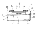
- FIG. 1 is a cross-sectional configuration diagram of a wipe storage body according to an embodiment of the present invention.
- FIG. 2 is a cross-sectional configuration diagram taken along the line AA in FIG.
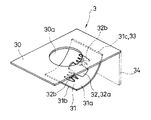
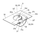
- FIG. 3 is a perspective configuration diagram of a built-in member (first example) constituting the wipe storage body of FIGS. 1 and 2.
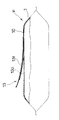
- FIG. 4 is a side configuration diagram showing a cross section of the main part of the bag body in which the configuration of the bag body constituting the wipe storage body is different from the example of FIG. 1, and the description of the built-in member is omitted.
- FIG. 5 is a side view showing a cross section of the main part of the bag body in which the structure of the bag body constituting the wipe storage body is different from the example of FIGS.
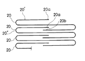
- FIG. 6 is a configuration diagram schematically showing a part of the wipes constituting the laminated body constituting the wipe storage body so that the structure of the laminated body can be easily understood.
- FIG. 7 is a perspective configuration diagram showing a partial modification of the built-in member (first example) shown in FIG.
- FIG. 8 is a perspective configuration diagram showing a partial modification of the built-in member (first example) shown in FIG.
- FIG. 9 is a perspective configuration diagram of a built-in member (second example) constituting the wipe storage body.
- FIG. 10 is a perspective configuration diagram of a built-in member (third example) constituting the wipe storage body.
- FIG. 11 is a perspective configuration diagram of a built-in member (fourth example) constituting the wipe storage body.
- FIG. 12 is a perspective configuration diagram of a built-in member (fifth example) constituting the wipe storage body.
- FIG. 13 is a perspective configuration diagram of a built-in member (sixth example) constituting the wipe storage body.
- FIG. 14 is a perspective configuration diagram of a built-in member (seventh example) constituting the wipe storage body.
- FIG. 15 is a perspective configuration diagram showing an elastically deformed state of a built-in member (seventh example) constituting the wipe storage body shown in FIG.
- the wipe storage body P is capable of taking out the laminated body 2 of sheet-like wipes 20 used as a wipe, a wipe, etc. one by one from the take-out portion 13, and is also water and various aqueous solutions. It is stored so that the wet state impregnated with can be maintained.
- the wipe storage body P includes a bag body 1, the laminated body 2, and a built-in member 3.
- the bag body 1 is made of a flexible packaging material having a function of suppressing evaporation and volatilization of moisture and the like impregnated in the laminate 2.
- the bag 1 is a flexible package composed of a plastic film or sheet.
- the bag body 1 is generated by a known method such as pillow packaging using the soft packaging material.
- the built-in member 3 and the laminated body 2 are accommodated in the bag body 1 in the process of generating the bag body 1.
- the bag body 1 has an upper surface portion 10, a lower surface portion 11, and four side surface portions 12 ... 12.
- the upper surface portion 10 of the bag body 1 is provided with a take-out portion 13 that allows the wipes 20 constituting the laminated body 2 to be drawn out in order from the top.
- the take-out portion 13 includes an opening 13 a formed in the upper surface portion 10 of the bag body 1 and a lid member 13 b that is fixed to the outer surface of the upper surface portion 10 of the bag body 1.
- the lid member 13b has a configuration in which a frame portion 13c and a lid body 13d are joined together by a hinge portion 13e.
- the frame portion 13c can be fixed by bonding the lower surface of the frame portion 13c to the outer surface of the upper surface portion 10 of the bag body 1 with the space in the frame communicating with the opening 13a of the bag body 1,
- the lid member 13b is fixed to the bag body 1 by fixing the frame portion 13c.
- the lid body 13d can stand up from the lying position superimposed on the upper surface of the frame portion 13c around the hinge portion 13e, closes the opening 13a in the lying position, and opens the opening 13a in the standing position. Is to be released. In the state where the lid body 13d is erected, the wipe 20 can be taken out from the bag body 1 through the opening 13a.
- the upper surface of the frame portion 13c and the lower surface of the lid body 13d have a structure that fits airtightly at the lying position of the lid body 13d.
- the take-out portion 13 includes an opening 13 a formed in the upper surface portion 10 of the bag body 1 and a lid member 13 b fixed to the outer surface of the upper surface portion 10 of the bag body 1. It is configured.
- the lid member 13b has a configuration in which a frame portion 13c and a lid body 13d are joined together by a hinge portion 13e.
- the frame portion 13c can be fixed by bonding the upper surface of the frame portion 13c to the inner surface of the upper surface portion 10 of the bag body 1 with the space in the frame communicating with the opening 13a of the bag body 1.
- the lid member 13b is fixed to the bag body 1 by fixing the frame portion 13c.
- the lid body 13 d is located outside the bag body 1.
- the lid body 13d is connected to a part of the frame portion 13c facing the outside of the bag body 1 via the hinge portion 13e.
- the lid body 13d can stand up from the lying position superimposed on the upper surface of the frame portion 13c around the hinge portion 13e, closes the opening 13a in the lying position, and opens the opening 13a in the standing position. Is to be released.
- the wipe 20 can be taken out from the bag body 1 through the opening 13a.
- the upper surface of the frame portion 13c and the lower surface of the lid body 13d have a structure that fits airtightly at the lying position of the lid body 13d.
- the take-out portion 13 is composed of an opening 13 a formed in the upper surface portion 10 of the bag body 1 and a flap sheet 13 f adhered to the outer surface of the upper surface portion 10 of the bag body 1.
- the flap sheet 13f has a size that covers the opening 13a, and its lower surface serves as an adhesive surface.
- the opening 13a is hermetically closed by adhering the outer edge of the flap sheet 13f to the opening edge of the opening 13a on the entire circumference of the opening 13a.
- the opening 13a is opened by peeling off the flap sheet 13f, and the wipe from the inside of the bag body 1 through the opening 13a is performed. 20 can be taken out.
- the laminate 2 is formed by superposing a plurality of wipes 20, 20.
- Each wipe 20 typically has a rectangular sheet shape, and each wipe 20 is configured to have the same size and shape.
- the wipe 20 is typically composed of paper, woven fabric, nonwoven fabric, or the like made of synthetic fiber or natural fiber.
- the laminate 2 is impregnated with various aqueous solutions such as water and chemicals.
- Each wipe 20 is stacked in a folded state as shown in FIG.
- the stacked body 2 has a rectangular parallelepiped shape by the plurality of wipes 20 stacked as described above.
- the lowermost wipe 20 constituting the laminate 2 is in contact with the lower surface portion 11 of the bag body 1, and a built-in member 3 described later is interposed between the uppermost wipe 20 and the upper surface portion 10 of the bag body 1.
- the bag body 1 in which the laminated body 2 is accommodated has a shape in which the lower surface portion 11 substantially follows the lower surface of the laminated body 2, and the upper surface portion 10 of the bag body 1 has substantially the same shape as the lower surface portion 11. It is supposed to have a size.
- each wipe 20 constituting the laminate 2 is linked to the adjacent wipe 20 in the stacking direction.
- the front end 20a of the wipe 20 'pulled out in the prior order (the end positioned on the pull-out side when being pulled out from the take-out portion 13) has the above-mentioned order
- the lamination is performed with the rear end 20b of the wipe 20 'sandwiched between the front end 20a of the wipe 20 "drawn out in the next order and the intermediate part of the wipe 20" in the next order (see FIG. 6).
- the next-order wipe 20 "is also moved in the pull-out direction.
- the laminated body 2 is constituted through the take-out portion 13 of the bag body 1.
- the next-level wipe 20 adjacent to the uppermost wipe 20 is drawn before the uppermost wipe 20 is pulled out from the bag 1.
- the front end 20a side is also moved to the take-out portion 13.
- a frictional resistance is applied to the drawer of the wipe 20 by a friction hole 32 of the built-in member 3 described later.
- the front end 20a side of the next-level wipe 20 is moved to the take-out portion 13 side as described above, but is not pulled out to the outside of the bag body 1. It is like that.
- the built-in member 3 allows the wiper 20 to pass through the first portion 30 in contact with the upper surface portion 10 of the bag body 1, the second portion 31 in contact with the laminated body 2, and the drawer, and causes friction resistance to act on the passage.
- a friction hole 32 and an elastic force generation mechanism 33 that generates an elastic force in a direction to separate the first portion 30 and the second portion 31 are provided.
- the volume of the laminated body 2 decreases as the number of wipes 20 drawn from the bag body 1, that is, the consumption amount of the wipes 20 increases.
- the elastic force generating mechanism 33 and the first portion 30 and the second portion 30 according to the decrease in volume.
- the distance between the two parts 31 is increased.
- the first portion 30 is always pressed against the upper surface portion 10 of the bag body 1 from the inside of the bag body 1 and the second portion 31 is always pressed on the upper surface of the laminated body 2. Pressed against the side facing the part 10. (See FIGS. 1 and 2) Therefore, it is possible to prevent the bag body 1 from being distorted or wrinkled due to the consumption of the wipe 20.
- the side surface portion 12 between the upper surface portion 10 and the lower surface portion 11 of the bag body 1 is always kept in a tensioned state without any wrinkles. Further, it is possible to prevent the gap between the friction hole 32 and the laminated body 2 from opening too much.
- the gap between the friction hole 32 and the laminated body 2 becomes too large, when the wipe 20 is pulled out, the friction hole 32 causes frictional resistance to act, and the wipe 20 that is pulled out in the previous order and the wipe 20 that is pulled out in the next order are used. The separation timing is delayed, and a situation in which the front end side of the wipe 20 of the next rank is pulled out to the outside of the bag body 1 is likely to occur.
- the front end of the next-order wipe 20 separated from the previous-order wipe 20 falls to the back side of the bag body 1 with respect to the friction hole 32, and the above-described next through the take-out portion 13. It becomes easy to cause a situation where it is difficult to perform an operation of picking and pulling the front end of the rank wipe 20.
- the first portion 30 is always pressed against the upper surface portion 10 of the bag body 1 from the inside of the bag body 1 regardless of the consumption amount of the wipe 20, and Since the second portion 31 is always pressed against the side of the laminated body 2 facing the upper surface portion 10, the above situation is prevented as much as possible.
- the first portion 30 of the built-in member 3 may be fixed to the upper surface portion 10 of the bag body 1 or may be fixed by adhesion or welding.
- the first portion 30 of the built-in member 3 has a rectangular plate shape having a contour that follows the contour of the upper surface portion 10 of the bag body 1.
- the first portion 30 is configured such that the entire upper surface of the first portion 30 is in contact with the upper surface portion 10 of the bag body 1 from the inside of the bag body 1.
- a through hole 30a of the wipe 20 communicating with the opening 13a is formed at a position immediately below the opening 13a in the first portion 30 configured as described above.
- the first portion 30 comes into contact with each corner portion 10 a of the upper surface portion 10 of the bag body 1.
- the first portion 30 can support the upper surface portion 10 of the bag body 1 so as not to be distorted at the corner portion 10a.
- the outer appearance of the bag body 1, that is, the wipe housing body P is always kept beautiful.
- the second portion 31 of the built-in member 3 has one side integrally connected to the first portion 30, the other side facing the one side is the free end 31 b, and the first portion 30 It is comprised by the plate-shaped body 31a comprised so that elastic deformation centering on the connection base part 31c of this could be carried out.
- the free end 31 b side of the plate-like body 31 a functions as the second portion 31.
- the plate-like body 31 a is connected to the first portion 30 between the through hole 30 a of the first portion 30 and one side portion along the width direction of the first portion 30.
- the plate-like body 31 a is connected to the first portion 30 so that the upper surface thereof faces the lower surface of the first portion 30 and the connecting base portion 31 c is along the width direction of the first portion 30. Further, the plate-like body 31 a is configured to have a width and a length that are smaller than those of the first portion 30. Further, the plate-like body 31a is configured so that the space between the connecting base portion 31c and the free end 31b is located directly below the through hole 30a.
- the built-in member 3 reduces the angle of the plate-like body 31a configured as described above from the position before elastic deformation indicated by the imaginary line in FIG. In an elastically deformed state, the bag body 1 is stored between the upper surface portion 10 and the laminated body 2. That is, in this example, the elastic force generating mechanism 33 is configured by the connecting base portion 31c of the plate-like body 31a configured to be elastically deformable in this way.
- the plate-like body 31a is curved so that the upper surface 10 side of the bag body 1 is a curved inner side, and the curved curved outer side is elastically pressed against the laminate 2.
- a friction hole 32 of the wipe 20 is formed at a location functioning as the second portion 31 in the plate-like body 31a. That is, in this example, the wipe 20 is pulled out of the bag body 1 through the friction hole 32 of the second portion 31, the through hole of the first portion 30, and the opening 13 a of the bag body 1.
- the friction hole 32 includes a center hole 32a, a branch hole 32b extending to the free end 31b side of the second portion 31 following the center hole 32a, and a connecting base portion 31c side of the second portion 31 following the center hole 32a.
- the central hole 32a has a size that allows the wipe 20 to pass therethrough.
- the two branch holes 32b and 32b are each formed in a meandering groove shape, and the friction hole 32 has a plurality of portions that are caught by the wipe 20 passing through the branch hole 32b configured as described above. ing.
- the second portion 31 when the second portion 31 is provided on the free end 31b side of the member (the plate-like body 31a) that is integrated at the upper portion and extends downward with respect to the first portion 30, On the side opposite to the free end 31b side of this member across the connecting base portion 31c with the first portion 30, it protrudes downward from the first portion 30 and makes its protruding end contact the lower surface portion 11 of the bag body 1.
- a supporting portion 34 (shown by an imaginary line in FIGS. 1 and 3) may be provided.
- the support portion 34 has a plate shape and is positioned between the laminated body 2 and one of the side surface portions 12 of the bag body 1.
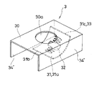
- FIG. 7 shows a structure in which the plate-like body 31a is connected to the first portion 30 by a hinge structure 35, and the plate-like body 31a is provided with an elastically deformable portion 33 ′ to constitute the elastic force generating mechanism 33.
- FIG. 7 shows a structure in which the plate-like body 31a is connected to the first portion 30 by a hinge structure 35, and the plate-like body 31a is provided with an elastically deformable portion 33 ′ to constitute the elastic force generating mechanism 33.
- FIG. 7 shows a structure in which the plate-like body 31a is connected to the first portion 30 by a hinge structure 35, and the plate-like body 31a is provided with an elastically deformable portion 33 ′ to constitute the elastic force generating mechanism 33.
- FIG. 7 shows a structure in which the plate-like body 31a is connected to the first portion 30 by a hinge structure 35, and the plate-like body 31a is provided with an elastically deformable portion 33 ′ to constitute the elastic force generating mechanism 33.
- the portions of the plate-like body 31a that are located outside the split groove 31d are strip-like portions 31f that are bent in an S-shape, and at positions displaced from the center of rotation in the hinge structure 35. It is connected to the portion 30.
- the built-in member 3 includes the upper surface portion 10 of the bag body 1 and the laminated body 2 in a state in which the band-shaped portion 31f is elastically deformed and the free end 31b of the plate-shaped body 31a is brought close to the first portion 30. It is paid in between. That is, in this example, the belt-like portion 31f functions as the elastically deformable portion 33 '.
- FIG. 8 includes support portions 34 ′ that protrude downward from the first portion 30 and have the protruding end in contact with the lower surface portion of the bag body 1 on both sides of the plate-like body 31 a in the built-in member 3.
- Each of the support portions 34 ′ has a plate shape and is positioned between the stacked body 2 and the side surface portion 12 of the bag body 1.
- the support portion 34 ′ can also maintain a constant distance between the upper surface portion 10 of the bag body 1 and the lower surface portion 11 of the bag body 1, and the bag body 1 can be maintained by the built-in member 3. Shape power can be further improved.
- the first portion 30 includes one band plate-like portion 30 b extending between two adjacent corner portions 10 a, 10 a among the four corner portions 10 a... 10 a in the upper surface portion 10 of the bag body 1.
- the other side band plate-like portion 30c extending between the remaining two corners 10a and 10a, and the connecting plate-like portion 30d connecting the middle of the one side band plate-like portion 30b and the middle of the other side band plate-like portion 30c. It is configured.
- the first portion 30 is in contact with each corner 10 a... 10 a of the upper surface portion 10 of the bag body 1. Thereby, even in this example, the upper surface portion 10 of the bag body 1 can be supported by the first portion 30 so as not to be distorted at the corner portion 10a.
- the appearance of the storage body P is always kept beautiful.
- a plate-like body 31 a having substantially the same configuration as that of the first example is integrated with the connecting plate-like portion 30 d of the first portion 30.
- FIGS. 1 to 3 showing the first example.
- the same reference numerals as those used are attached to FIGS. 8 to 13 and the description thereof is omitted.
- the first portion 30 includes one band plate-shaped portion 30 e extending between two adjacent corner portions 10 a, 10 a of the four corner portions 10 a... 10 a in the upper surface portion 10 of the bag body 1.
- the other side band plate-shaped portion 30f extending between the remaining two corners 10a and 10a, and the connecting plate-shaped portion 30g that connects one end of the one side band plate-shaped portion 30e and one end of the other side band plate-shaped portion 30f. It is configured.
- the first portion 30 comes into contact with each corner portion 10 a of the upper surface portion 10 of the bag body 1. Thereby, even in this example, the upper surface portion 10 of the bag body 1 can be supported by the first portion 30 so as not to be distorted at the corner portion 10a.
- the appearance of the storage body P is always kept beautiful.
- a plate-like body 31 a having substantially the same configuration as that of the first example is integrated with the connecting plate-like portion 30 g of the first portion 30.
- the plate-like bodies 31a constituting the first portion 30 and the second portion 31 of the built-in member 3 both have a rectangular plate shape.
- the first portion 30 has its corners in contact with each corner 10 a of the upper surface portion 10 of the bag body 1. Thereby, even in this example, the upper surface portion 10 of the bag body 1 can be supported by the first portion 30 so as not to be distorted at the corner portion 10a.
- the appearance of the storage body P is always kept beautiful.
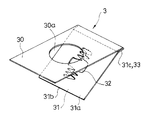
- the first portion 30 and the plate-like body 31a are integrated by connecting one side of the first portion 30 and one side of the plate-like body 31a.
- the plate-like body 31a is configured to cause elastic deformation around the connecting base portion 31c with the first portion 30.
- the free end 31 b side of the plate-like body 31 a functions as the second portion 31.
- the built-in member 3 elastically deforms the plate-like body 31a configured as described above from the position before elastic deformation to increase the angle with the first portion 30 so as to reduce the angle. In the state, it is stored between the upper surface portion 10 of the bag body 1 and the laminated body 2. That is, in this example, the elastic force generating mechanism 33 is constituted by the connecting base portion 31c of the plate-like body 31a.
- the second portion 31 is formed with the friction hole 32 substantially the same as the first example.
- both the first portion 30 and the second portion 31 of the built-in member 3 have a rectangular plate shape.
- the first portion 30 has its corners in contact with each corner 10 a of the upper surface portion 10 of the bag body 1. Thereby, even in this example, the upper surface portion 10 of the bag body 1 can be supported by the first portion 30 so as not to be distorted at the corner portion 10a.
- the appearance of the storage body P is always kept beautiful.
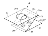
- the first portion 30 and the second portion 31 are integrally connected to one side portion (right side portion in FIG. 11) of the first portion 30 and the one side portion (left side in FIG. 11) of the second portion 31.
- a through hole 36 c of the wipe 20 is formed in the intermediate portion 36.
- the intermediate portion 36 is configured to undergo elastic deformation around the connecting base portion 36 a with the first portion 30 and the connecting base portion 36 b with the second portion 31.
- the built-in member 3 reduces the angle of the intermediate portion 36 configured in this way from the position before elastic deformation that increases the angle between the first portion 30 and the second portion 31.
- the bag body 1 is accommodated between the upper surface portion 10 and the laminated body 2. That is, in this example, the elastic force generating mechanism 33 is formed by the intermediate portion 36 configured to be elastically deformable in this way, that is, the elastically deformable portion 33 ′ that connects the first portion 30 and the second portion 31. It is configured.
- the second portion 31 is formed with the friction hole 32 substantially the same as the first example.
- the first portion 30 of the built-in member 3 is divided into four parts.
- Each of the first portions 30 is located inward of the bag body 1 at the corresponding corner portion 10a of the four corner portions 10a... 10a of the upper surface portion 10 of the bag body 1 via the intermediate portion 37 above the second portion 31. It is arranged to touch.
- the second portion 31 has a rectangular plate shape.
- Each first portion 30 and second portion 31 are integrated by an intermediate portion 37 having a curved plate shape.
- Each intermediate portion 37 is configured to have a curvature with the inner side of the bag body 1 as the curved outer side, and to generate an elastic deformation that increases the curvature of the curvature.
- the built-in member 3 reduces the distance between the intermediate portion 37 thus configured from the position before elastic deformation that increases the distance between the first portion 30 and the second portion 31.
- the bag body 1 is accommodated between the upper surface portion 10 and the laminated body 2. That is, in this example, the elastic force generating mechanism 33 is formed by the intermediate portion 37 configured to be elastically deformable in this way, that is, the elastically deformable portion 33 ′ that connects the first portion 30 and the second portion 31. It is configured.
- the second portion 31 is formed with the friction hole 32 substantially the same as the first example.
- the built-in member 3 uses the end of two opposing side portions of the plate-like body 31 a having four side portions as the first portion 30, and the plate between the two first portions 30.
- the upper part of the shape 31a is curved so as to be inside the curve, and the lowermost part thereof is used as the second part 31, and the friction hole 32 substantially the same as that of the first example is provided at the lowermost part.
- the plate-like body 31 a is between the first portion 30 and the second portion 31, and has a first fold line portion 38 parallel to the end of the side that becomes the first portion 30, and the first fold line portion 38.
- a second fold line portion 38 ′ is provided on the second portion 31 side and parallel to the first fold line portion 38.
- the built-in member 3 of this example is a bag body in a state where the side portion of the plate-like body 31a is bent by elastic deformation at the first fold line portion 38 and the second fold line portion 38 ′. 1 is placed between the upper surface portion 10 and the laminate 2. That is, in this example, the elastic force generating mechanism 33 is configured by an elastically deformable portion 33 ′ formed between the first portion 30 and the second portion 31.
- the present invention is not limited to the embodiment described above, but includes all embodiments that can achieve the object of the present invention.
Landscapes
- Engineering & Computer Science (AREA)
- Mechanical Engineering (AREA)
- Packages (AREA)
Abstract
L'invention concerne un corps de réception de lingettes comportant : un emballage qui reçoit une pile de lingettes en feuille et comporte, sur la face supérieure, une section d'extraction qui permet aux lingettes composant la pile d'être retirées dans l'ordre à partir du haut; et un membre interne qui est intercalé, dans l'emballage, entre la pile et la face supérieure de l'emballage. Le membre interne comprend une première partie qui est en contact avec la face supérieure, une seconde partie qui est en contact avec la pile, un trou de frottement qui est ménagé sur la seconde partie et qui applique une résistance par frottement au passage des lingettes, et un mécanisme de production de force élastique qui produit une force élastique pour séparer la première partie et la seconde partie.
Priority Applications (1)
| Application Number | Priority Date | Filing Date | Title |
|---|---|---|---|
| PCT/JP2013/066661 WO2014203321A1 (fr) | 2013-06-18 | 2013-06-18 | Corps de réception de lingettes |
Applications Claiming Priority (1)
| Application Number | Priority Date | Filing Date | Title |
|---|---|---|---|
| PCT/JP2013/066661 WO2014203321A1 (fr) | 2013-06-18 | 2013-06-18 | Corps de réception de lingettes |
Publications (1)
| Publication Number | Publication Date |
|---|---|
| WO2014203321A1 true WO2014203321A1 (fr) | 2014-12-24 |
Family
ID=52104090
Family Applications (1)
| Application Number | Title | Priority Date | Filing Date |
|---|---|---|---|
| PCT/JP2013/066661 Ceased WO2014203321A1 (fr) | 2013-06-18 | 2013-06-18 | Corps de réception de lingettes |
Country Status (1)
| Country | Link |
|---|---|
| WO (1) | WO2014203321A1 (fr) |
Cited By (2)
| Publication number | Priority date | Publication date | Assignee | Title |
|---|---|---|---|---|
| US10894656B2 (en) | 2016-11-11 | 2021-01-19 | Kimberly-Clark Worldwide, Inc. | Storing and dispensing container for wipes |
| JP2021035848A (ja) * | 2019-08-30 | 2021-03-04 | 株式会社タイキ | ウェットシート包装体 |
Citations (4)
| Publication number | Priority date | Publication date | Assignee | Title |
|---|---|---|---|---|
| GB1085560A (en) * | 1965-05-15 | 1967-10-04 | Int Paper Canada | Carton |
| JPS5549612U (fr) * | 1978-09-28 | 1980-04-01 | ||
| JP3048088B2 (ja) * | 1992-07-13 | 2000-06-05 | 横河電機株式会社 | アナログ信号レベル調整装置 |
| JP2005519822A (ja) * | 2002-03-12 | 2005-07-07 | スリーエム イノベイティブ プロパティズ カンパニー | 一体型ブリスタ・スプリングを備えたポップアップ・シート材料ディスペンサ |
-
2013
- 2013-06-18 WO PCT/JP2013/066661 patent/WO2014203321A1/fr not_active Ceased
Patent Citations (4)
| Publication number | Priority date | Publication date | Assignee | Title |
|---|---|---|---|---|
| GB1085560A (en) * | 1965-05-15 | 1967-10-04 | Int Paper Canada | Carton |
| JPS5549612U (fr) * | 1978-09-28 | 1980-04-01 | ||
| JP3048088B2 (ja) * | 1992-07-13 | 2000-06-05 | 横河電機株式会社 | アナログ信号レベル調整装置 |
| JP2005519822A (ja) * | 2002-03-12 | 2005-07-07 | スリーエム イノベイティブ プロパティズ カンパニー | 一体型ブリスタ・スプリングを備えたポップアップ・シート材料ディスペンサ |
Cited By (2)
| Publication number | Priority date | Publication date | Assignee | Title |
|---|---|---|---|---|
| US10894656B2 (en) | 2016-11-11 | 2021-01-19 | Kimberly-Clark Worldwide, Inc. | Storing and dispensing container for wipes |
| JP2021035848A (ja) * | 2019-08-30 | 2021-03-04 | 株式会社タイキ | ウェットシート包装体 |
Similar Documents
| Publication | Publication Date | Title |
|---|---|---|
| JPWO2014142091A1 (ja) | ワイプディスペンサ | |
| CN105283391A (zh) | 湿纸巾包装体 | |
| RU2288153C2 (ru) | Упаковка для одноразовых предметов | |
| WO2013132782A1 (fr) | Unité d'emballage de tissus humides | |
| CN101925523A (zh) | 包装体 | |
| CN105050916A (zh) | 擦拭物包装体 | |
| WO2014203321A1 (fr) | Corps de réception de lingettes | |
| JP5722620B2 (ja) | 包装用ケースのシート接続構造及び包装用ケース | |
| JP2016030626A (ja) | 包装容器 | |
| JP6677555B2 (ja) | ポップアップ式ペーパー収容体 | |
| JP2012153396A (ja) | 包装用パッケージ | |
| JP7195394B2 (ja) | 収容体、及び薄葉紙製品 | |
| JP2013159365A (ja) | 包装体及び包装体の開閉蓋 | |
| JP5352172B2 (ja) | 家庭用薄葉紙収納容器 | |
| JP2009286447A (ja) | 家庭用薄葉紙収納箱 | |
| CN214493721U (zh) | 一种扣合式折叠包装盒 | |
| JP5574444B2 (ja) | 補充可能な付箋収納部の構造 | |
| KR20110121268A (ko) | 덮개판이 원터치로 동시에 접혀지는 포장용 박스 | |
| KR101574738B1 (ko) | 포장용박스 | |
| JP3166100U (ja) | シート状物収納用紙箱 | |
| JPH0645384B2 (ja) | 包装体 | |
| US1028084A (en) | Paper towel and napkin package. | |
| JP3830204B2 (ja) | メモパッド容器兼ディスペンサ | |
| KR20140002804U (ko) | 물품 케이스 | |
| CN222523262U (zh) | 一种包装组件 |
Legal Events
| Date | Code | Title | Description |
|---|---|---|---|
| 121 | Ep: the epo has been informed by wipo that ep was designated in this application |
Ref document number: 13887578 Country of ref document: EP Kind code of ref document: A1 |
|
| NENP | Non-entry into the national phase |
Ref country code: DE |
|
| 122 | Ep: pct application non-entry in european phase |
Ref document number: 13887578 Country of ref document: EP Kind code of ref document: A1 |
|
| NENP | Non-entry into the national phase |
Ref country code: JP |